Structural health monitoring (SHM) is a rapidly evolving field, and there is a vast literature covering several topics that are related to this field. This entry is focused on the analysis of the state of the art of sensors for guided ultrasonic waves for the detection and localization of impacts for structural health monitoring (SHM).
- structural health monitoring (SHM)
- acoustic emission
- guided waves
- Lamb waves
- sensors
- ultrasound
- piezoelectric
- composites
- piezopolymers
- PVDF
- interdigital transducer (IDT)
- PWAS
- CMUT
- mems
- analog electronic front end
- analog signal processing
- impact localizati
1. Introduction
Structural health monitoring (SHM) is a rapidly evolving field, and there is a vast literature covering several topics that are related to this field, including several excellent reviews. The motivations of this paper are to report the recent developments on technologies, especially sensors and mixed signal electronic interfaces, which enable integration into a sensor node. The sensor node concept is analyzed in this review and the perspective for integrating with monitored facilities is examined. In the introduction the main concepts behind the design of a SHM system for impact monitoring and main review papers are reported. Later in the introduction, the main system components are defined and, in the following sections, they will be discussed more deeply.
Ultrasonic non-destructive investigation (NDI) methods that are based on the principle of acoustic emission (AE) have evolved over the past two decades towards structural monitoring systems with guided ultrasonic waves [1][2], driven by applications in the aerospace, civil engineering, energy conversion, and transportation systems automotive (e.g., wind turbines, pipelines, and liquid natural gas cylinders). The safety of the structure and the prediction of in-service period are the key elements that must be provided by SHM and the underlying theory about these topics were explained in a comprehensive work by Farrar and Worden [3] and in a related book [4]. Structure damaging can occur for different causes (e.g., breakages due to fatigue, mechanical and thermal stresses, impacts with objects, etc.), and their consequences often are not optically visible or detectable. The damage is sometimes not visible, because it is internal to the structure or small but not without importance from the point of view of the safety and reliability of the operation of the system. To avoid catastrophic accidents, the damage prognosis is an essential task that is connected to the impact events; a framework for the damage prognosis was described in chapter 14 of the book that was published by Farrar and Worden [5].
Non-Destructive Testing (NDT) is a wide group of analysis techniques used in science and technology industry to evaluate the properties of a material, component, or system without causing damage, and it is often carried out in laboratory or on site on a scheduled program. SHM, unlike NDT, requires the installation of sensors/transducers operating in the environment in which the structure operates under remote control and for this reason the realization of such systems requires a considerable effort of integration of several disciplines:
-
(modelling of damage physical phenomena and their influence on the physical sensed quantities,
-
sensors, including calibration and self-diagnostics,
-
front-end electronics including embedded processing,
-
data transmission (wired, wireless),
-
online (or real time) or offline signal/image processing,
-
impact event detection and localization
-
damage detection and classification techniques that are based on database processing,
-
prognostics,
-
artificial intelligence (AI)/machine learning (ML) for automatic damage detection and progression evaluation.
Figure 1 illustrates the different components of an SHM system and their interaction: the environmental conditions, the on-site hardware, and the off-site hardware and software resources. The different characteristics of the structures (dimensions, materials, and environmental conditions) and their structural monitoring systems (cost, footprint, weight, power consumption, safety and reliability criteria, and response/update times) often require the design of ad hoc systems by exploiting multidisciplinary knowledge in electronics, informatics, telecommunications, and, finally, material technology and mechanical properties.
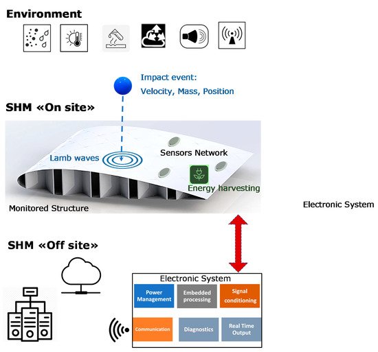
Figure 1. Graphical representation of an advanced structural health monitoring (SHM) system for impact monitoring. (Top) Environmental conditions (dust, moisture, temperature, pressure, vibrations, electromagnetic interference) and impact events characterized by the object mass, velocity, shape and dimensions. (Centre) On-site components of the SHM system subjected to environment conditions installed on the monitored structure (e.g., a section of a composite airplane wing). (Bottom) Off-site components installed remotely and connected to the sensors network; the Electronic System can operate in a protected environment (e.g., inside airplane fuselage) with real-time processing capability. Off-line signal/data processing based on big data archive with workstations connected to the web for software applications of Artificial Intelligence/Machine Learning (AI/ML) and prognostics.
For a general understanding of the state of the art, the reader can refer to the review paper of Mitra et al. [6], where several publications relating to the various components of an SHM system are discussed (see Figure 1); in the paper of Mitra et al. [6], various monitoring techniques based on ultrasonic guided waves (UGW) piezoelectric and fiber optic sensors, laser vibrometry (SLDV) techniques are examined. In addition, indications are given of what research and development lines may be for advanced SHM systems. As already introduced in this paragraph, monitoring techniques that are based on UGW by piezoelectric transducers are among the most common and most developed, since they have a longer history [7] than SHM systems based on optical sensors, in particular Fiber Bragg Grating (FBG) sensors; for completeness, the evolution of state of the art for optoelectronic sensors is reported in [8][9][10][11][12], but it is not discussed further in this paper. Similarly, the evolution of piezoelectric materials for the construction of UGW sensors and transducers, the development of low-power consumption integrated electronic components and systems requires a continuous updating of research to provide new design methodologies and technologies to bring in the field the SHM systems. Although many published papers report the outcomes that were obtained with laboratory set-up of guided ultrasonic wave SHM systems, their demonstration in the field is still limited. For the latter problem, there are various reasons, but certainly one of these is the complexity of the installation of the sensors on a target structure, the real time signal acquisition and processing, and the replication of the real-life environmental conditions. An interesting reference for the testing of SHM systems in the aerospace industry is provided in a report that was presented by Dennis Roach of Sandia National Labs [13]: this report shows the objectives and implementations of SHM systems for airplanes and includes several examples with piezoelectric and fiber optic sensor applications for monitoring impacts, deformations, debonding, delamination, and damage progression.
Finally, it is useful to point out the effort made to create standards for the development of systems and methods for SHM and NDT based on acoustic emission, especially for the rapidly evolving SHM sector; a comprehensive reference is the British Standard for Acoustic Emission and Condition Monitoring that was published in The Official Yearbook of the British Institute of Non-Destructive Testing [14]. Some main book references on SHM based on UGW can be found in [15][16][17][18][19]. After this introduction of the background of SHM systems that are based on UGW in active and passive modes, the present paper focusses the elements of the system that is shown in Figure 1 for the implementation of impact monitoring advanced systems on metal and composite materials with UGW piezoelectric sensors. In this paper, we primarily consider piezoelectric sensors used for impact detection in passive (“listening”) mode, but also in combination with the transducers operating in active mode for the investigation of damage and its progression over time. The trend of integrating different sensor types (UGW, FBG, accelerometer, strain, temperature, etc.) into a node increases the information regarding the impact and the operational conditions of the sensors that are influenced by the environment, leading to the concept of a “multifunctional sensor node”.
The evolution from the common AE monitoring configuration with a layout of sparse single element sensors with off-the shelf electronics to the recent design of sensors networks with “smart-sensor nodes” requires a continuous analysis and evaluation of the progresses in several fields.
2. Characteristics of Signals Generated by Impacts on Planar Structures Relevant to the Design of SHM Systems
2.1. Dispersion and Attenuation of Lamb Waves
In this section, the implication of the attenuation and dispersion characteristics of UGW relevant for the design and implementation of a SHM system are discussed. The interested reader can find main references for the theory and modelling of ultrasonic guided waves [1][20]. In brief, we point out that ultrasonic waves that are guided for SHM are mechanical waves that propagate within a material delimited by an interface with a different medium. Propagation within the space-limited structure simultaneously produces dispersive modes of propagation in frequency. In the case of structures with thicknesses comparable to wavelength, such as thin planar structures, propagation modes have symmetrical and antisymmetric characteristics with respect to the axis of symmetry of the structure and they are determined by the theory behind Lamb waves, as explained in [21]. For an isotropic and homogeneous laminate material (e.g., aluminum), we illustrate the dispersion characteristics in Figure 2 (top) by the calculated phase velocities for the different guided modes versus the frequency x thickness product (fxd). Another difference between these two UGW modes is the dependence on frequency attenuation, as shown in Figure 2 (bottom): the S0 mode is remarkably attenuated in the low frequency range and for the reception of this mode is necessary a high pass filtering and amplifier gain to be separated from the slower and higher amplitude components of the A0 mode.
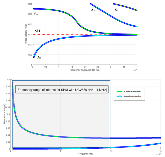
Figure 2. (Top) Simulated dispersion curves of phase velocity for low order modes Symmetric (S0), Antisymmetric (A0) and Shear Horizontal (SH) in an aluminum plate as function of the frequency × thickness product (MHz × mm). The diagram shows that higher order modes (A1, S1, etc.) are generated well above the value of 1.5 MHz × mm. (Bottom) Frequency dependent attenuation of Symmetric (S0) and Antisymmetric (A0) modes calculated as imaginary part of the complex wavenumber K for an aluminum plate 1.4 mm thick.
Therefore, the propagation of symmetrical modes within a planar structure is a two-dimensional phenomenon; the propagation of the various modes is subjected to attenuation that mainly follows the law of geometric decay inversely at the root of the distance. The authors in [20] proposed a deep and comprehensive analysis of the attenuation phenomena that are basic in differentiating the design of SHM systems according to the characteristics of the different materials (composite or metallic) and the size of the structure; thus, attenuation analysis is essential in defining the distance and area coverage with a certain type of transducer/sensor without exceeding the attenuation limit (50–70 dB), which results in being difficult to deal with analog-front-end (AFE) electronics based on COTS, unless it has an acceptably expensive and complex electronic customized design. Indicatively, the operating frequencies for Lamb’s guided ultrasonic waves range from 100 kHz to 1 MHz and, in this wide range, a compromise must be found between attenuation, wavelength, minimum detectable impact energy, and for the transducers/sensors, the size, type, sensitivity, and bandwidth. To solve these problems, methods for optimizing the position of transducers have recently been proposed by Mallardo et al. [22] based on the background of UGW propagation theory; in this work, a method is developed to define the optimal positions considering the characteristics of the material and sensors, thus also optimizing the number of sensors transducers, while concluding that there is no general solution to the problem, since each application has different constraints and, therefore, requires a series of a priori choices.
2.2. Ultrasonic Guided Waves Generated by Different Velocity of Impacts on Isotropic Elastic Plates
Impact monitoring systems can be designed for different applications, where impacts with different objects hitting the structure have different energy, mass, and velocity. It is of interest to explain the different effects on UGWs that were generated by impacts at different velocity. There are several categories of impact loading: low velocity (large mass), intermediate velocity, high/ballistic velocity (small mass), and hyper velocity impacts. These categories of impact loading are important because there are remarkable differences in energy transfer between the object and target, energy dissipation, and damage propagation mechanisms as the velocity of the object varies. Low velocity impacts occur typically at a velocity below 10 m/s, intermediate impacts occur between 10 m/s and 50 m/s, high velocity (ballistic) impacts have a range of velocity from 50 m/s to 1000 m/s, and hyper velocity impacts have the range of 2 km/s to 5 km/s, according to the literature [23].
In several studies [19][20][21], the signals generated by non-destructive impacts have been treated, which is impacts that do not cause any damage to the laminate under examination. These papers consider single and multiple impacts, but detailed information on the energy characteristics is not provided regarding the impacts analyzed. Furthermore, in [22], the impacts are distinguished based on the potential energy of the impacting bodies, with values ranging from 500 mJ to 3.5 mJ. In other early studies on this subject [23][24], the impacts are instead distinguished based on the impact velocity. In several studies [24][25][26], signals that are generated by non-destructive impacts have been treated, which is, they do not cause any damage to the laminate under examination, neither with single impact nor with multiple impacts, however no information is given on the extent of impact. Furthermore, in [27], the impacts are distinguished based on the potential energy of the impacting bodies, with values ranging from 500 mJ to 3.5 mJ. In other early studies on this subject [28][29], the impacts are instead distinguished based on the impact velocity.
The study of impacts that occur in an isotropic elastic flat plate is based on following assumptions:
-
The ultrasonic signal that is generated by an impact is a guided wave signal that propagates into the plate without energy loss [24][30].
-
The frequency content of the ultrasonic signals that are generated by impacts depends on the impact velocity [28][31] and it is not modified during the propagation inside the plate [32].
According to the above assumptions, we can remark that the main feature of the signals generated by impacts is the impact velocity that also determines the amplitude of the Lamb waves. From the physics laws for a falling body from a certain height, the potential energy is converted to kinetic energy; the impact velocity vi can be calculated by knowing the kinetic energy Ek and the mass m of the impacting object, as reported in the following formula:
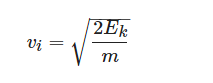
The study reported in [28] shows that two fundamental propagation modes can be distinguished in impact phenomena: a slow propagation mode (flexural mode or A0 mode) and a fast propagation mode (extensional mode or S0 mode).
The amplitude of the signal in A0 mode is dominant as compared to the S0 mode, but the amplitude of the latter is strongly linked to the speed of the impact: the greater the speed of the impact the greater the amplitude of the signal relative to the S0 mode. The authors in [28] also reported an acquired signal from a high-speed impact (700 m/s), where they demonstrate, when that applying a low-pass filter with (with a cut-off frequency of 800 kHz), it is possible to only extract the two fundamental propagation modes (A0 and S0) and, in this case, the amplitude of the S0 mode becomes comparable to that of the A0 mode. According to the authors experience, we investigated the possibility to also extract the S0 mode signal in low velocity impacts by applying a low-pass filter in the analogic front-end electronic board with proper cut-off frequency. Figure 3 shows ultrasonic signals that are generated by a low-velocity impact (about 3 m/s) on an aluminum plate with thickness 1.5 mm.
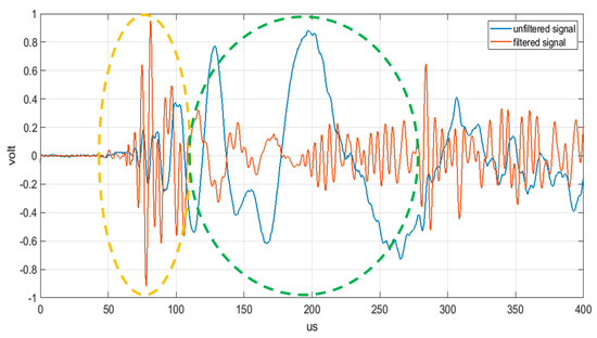
Figure 3. Ultrasonic signals generated by a low-velocity impact (about 3 m/s) in blue color, and the same signal filtered by an analogic low-pass filter with a cut-off frequency of 400 kHz in red color. The dotted green circle represents the portion of the signal relative to the A0 mode; the dotted yellow circle represents the portion of the signal relative to the S0 mode.
From the analysis of Figure 3, it is apparent that the fast propagation mode S0 becomes comparable in amplitude with the A0 mode only after filtering the ultrasonic propagating signal that is generated by the impact. The possibility of processing the fast S0 mode instead of the slower A0 mode, is often the best signal processing design strategy, because this early arrival time signal is less affected by overlapping of the multiple reflections from the structure edges [33]; moreover, the impact signal detection and positioning is even more complicated in large structures for the higher attenuation and the mode conversions after the propagation on areas with different thicknesses. The topics briefly reviewed in this section remark the importance of the understanding the physical background for designing sensors and the analog front-end to simplify and make the information extraction from the signal reliable.
2.3. Signal Processing Techniques for Dispersion and Environmental Factors Compensation
From the preliminary considerations in the Introduction, we can remark that the rapid evolution towards integrated-SHM (ISHM) systems operating in different environmental conditions follows a different path than the common AE and NDT techniques, which use volumetric longitudinal or transverse ultrasonic waves with piezoelectric transducers that are connected to portable instruments and the region of interest (ROI) manually scanned of by a trained operator [34]; main differences are found for the signal processing adopted for both passive and active mode operation of the SHM system. The analysis of information gathered by a sensors layout due to the interaction between the UGW dispersive modes and the various types of structures is certainly a challenging aspect from the point of view of signal processing techniques that are based on the Continuous Wavelet Transform (CWT) or the Short Time Fourier transform (STFT). CWT decomposes a time domain signal into components that correspond to a frequency band. Each of these components contains a further temporal discretization. The resolution of the temporal discretization varies with each frequency component, resulting in a multi-resolution temporal frequency analysis. Because the modes S0 and A0 propagate with different amplitudes in the useful band and with different propagation speeds (see Figure 2), the CWT allows for a representation capable of separating the two contributions in different instants of time. One of the limitations of the CWT is the compromise between resolution in frequency and in time and, moreover, the calculation algorithm requires considerable computational resources, not always available within a sensor node. Alternatively, the simplest form is represented by the STFT, but, differently from CWT, does not have the possibility to be implemented with the multi-resolution functionality in the time/frequency domain. For example, the separation of the two modes S0 and A0 by CWT o STFT is relevant for the evaluation of the DToAs for low and high velocity impacts, as we will describe in Section 2.2. However, simple analysis with CWT or STFT may still be too restrictive in the presence of structures with inserts, reinforcement elements, and therefore several methods have recently been proposed to overcome this problem, such as those reported in [30][31][32][35][36][37]. The well-known time-reversal approachis another important method introduced in [38] to compensate for the dispersion and alleviate the complexity of Lamb wave signal interpretation; this approach was adopted by Zeng et al. [39]. The dispersion of the generated modes by impacts influences the spatial resolution of the adopted localization algorithm, because the propagation on long distances (e.g., meters) [40] on the plate elongates the initial wavelet. The mitigation of this problem can be done using algorithms that can process the received signals by compensating the phase delay according to the theory of UGW [1]. There are available efficient algorithms for this task, such as multiple signal classification (MUSIC) and RAPID [41]. New developments that are based on the MUSIC algorithm have been proposed for impact energy estimation [42] and for the direction of arrival of a Lamb wave [43]. The computational efficiency is also important for real-time systems and Zhong et al. proposed an improvement in the processing scheme [44].
The UGWs used in active mode for damage assessment have a great sensitivity to detect internal damage into the structure, and this is one of the main reasons of successful application of this NDT technique. The detection is often implemented on a data driven approach, where the received UGWs from a sensor layout are compared with a baseline of data acquired with a pristine structure. This approach is also rather simple to implement in sensors with on board embedded processing, but it suffers from the sensitivity to environmental and operational conditions, mainly temperature variations. Recently, Mariani et al. [45][46] have proposed a method for the compensation of this detrimental phenomenon. For the electro-mechanical-impedance (EMI) method, the temperature compensation was achieved with some benefits by using artificial neural network (ANN) as reported by Sepehry et al. [47].
2.4. Advanced Methods for Impact Detection and Localization
In general, impacts on a thin planar structure generate guided waves modes that can propagate away from the impact point. The localization of the impact point is commonly achieved by adopting a triangulation algorithm with at least three passive ultrasonic sensors being deployed on the planar structure. The accuracy of the impact point estimation depends on the estimates of the guided modes velocity and the measured differential time of arrival (DToA) among the sensors [48]. Recently, several papers have been published to improve the reliability and accuracy of impacts on complex structures other than from the simple panels often used by researchers in laboratory for calibration and performance assessment of a SHM system. The Akaike Information Criterion (AIC) criterion for the accurate estimation of DToA has been demonstrated by De Simone et al. [49]. Further research work has consolidated the investigation of the advantages of AIC, and a modified version for impact monitoring has been recently proposed by Seno et al. [50]. In the latter work, an ANN was trained for automatic classification of defects in composite materials that were tested in laboratory and simulated operational conditions. As already reported in the Introduction, Ono reports an extensive review of AE physical parameters for SHM systems in [20]. The characteristic of UGW generated by impacts has been outlined in Section 2.1 and Section 2.2. Such guided wave modes propagating into the planar structure mix-up due to the phase velocity dispersion and, in addition, the reflection phenomenon from the edge or from inserts or stiffening material or defects [51]. Moreover, mode conversion can occur when the ultrasonic guided waves travel across a discontinuity of acoustic properties in the planar structure, for example, a change in thickness or material composition. In general, the wave shape of the impact generated UGW is complex, but a list of features supported by theoretical modelling developed by Hakoda et al. [52] based on the phase velocity analysis can be derived. It is worth noticing that the propagation velocity analysis, in general, is more complex for a composite three-dimensional structure than the simpler case shown in Figure 2; even the example of time domain signals generated on an aluminum plate reported in Figure 3 is a simplified scenario with respect to real-life cases. In the following, we report two main considerations that are starting guidelines for the impact signals processing:
- the early part of the signal consists of the fast phase velocity modes, typically the S0 mode in the low frequency range below the cut off frequency × thickness product (e.g., equal to 1.5 MHz × mm in Figure 2).
-
in the later part of the signal the contribution comes from slower modes that show also dispersion effect as for the A0 mode [53] or signals that travelled along longer paths or multiple reflections.
We can observe that the S0 mode being faster than A0 it is less prone to being overlapped by delayed signals, but, due to the greater attenuation at low frequencies, the S0 mode has a lower amplitude than the A0 mode; the higher velocity of this mode also implies that the error on its DToA estimation causes higher spatial errors in the triangulation algorithms or any other positioning method based on DToA [54][55][56]. The theory of UGW in a plate like structure also considers other types of waves than Symmetrical and Antisymmetrical Lamb wave modes: the shear horizontal (SH) mode. This is a non-dispersive mode and piezoelectric sensors/transducers can be designed to convert this wave type into voltage signals. Ren and Lisseden [57] have demonstrated the capability of also sensing Lamb waves that are of interest for impact detection in passive mode. Altammar et al. [58] studied the actuation and reception of shear modes by exploiting the d35 piezoelectric coefficient of lead zirconate titanate (PZT) sensors that were embedded in a laminate structure. d35 PZT is a class of PZT piezoelectric transducers that, when polarized along their thickness, they induce shear strain in the piezoelectric material. It is interesting to observe that the shear deformation has a stronger coupling coefficient (d35) than the common d33 or d31, indicating that d35 PZTs have stronger electromechanical coupling for sensing and actuation.
In the final part of this section, we review the advancements on signal processing techniques for anisotropic plate-like material. Anisotropic characteristics of composite structure require the adaption of impact positioning algorithms that were developed for isotropic plate like materials. The early research on signal processing techniques for isotropic metallic plates and anisotropic composites can be found in [26][56][59][60]. More recently, the signal processing techniques have been progressed to account for the UGW dispersion (see Section 2.1) and anisotropy of different type of composites, like unidirectional, quasi-isotropic composite fiber reinforce polymer (CFRP), and honeycomb, which are of interest for aerospace industry [39][49][56][61][62]. An early work of Scholey and Wilcox in 2010 [63] addressed the problem of impact detection on 3D structures and, recently, Moron et al. in 2015 [64]. Lanza di Scalea et al. published a work [65] for impact monitoring in complex composite material structure with an algorithm that is based on the rosette sensor configuration; this model-based approach could solve the problem of variation of phase velocity along different direction of a composite material.
3. Hardware Developments of Wired and Wireless Sensor Networks (WSNs) for SHM and Validation Tests
From the previous sections, it turns out that, in recent years, the combination of several progresses in sensors and mixed signals low power electronics have introduced a new paradigm for the SHM systems that is the network of sensors nodes, as reported by Farrar et al. [66]. Figure 4 shows a conceptual description of the migration from single distributed sensors on a structure to the sensor network, where, for example, the authors represented a sensor network for monitoring a COPV system. In the same picture are shown the main electronic blocks that are needed to realize a sensor node with active and passive mode operation. The transducer driver (for broadband or narrow band ultrasonic transducers) and the signal conditioning are both controlled by a mixed signal System on Chip (SoC). The connections between nodes and the central unit (see architecture in Figure 4) can be implemented with wired solutions where the power lines for the nodes can sustain a sufficient data rate by using power line communication (PLC) protocols and related chipset. Simplified connection schemes and a low power digital electronic front end has been recently proposed and validated on an aircraft wing by Qiu et al. [67]. The SoC development of a node with passive and active mode operation poses several design issues that are related to the electronic design. The main issues are the power consumption and design of an efficient ultrasonic pulser to gain transduction efficiency in active mode [68]. Local high voltage power amplifiers or pulsers are needed to excite transducers with 10 V to 100 V amplitude excitation signals; the local availability of high voltages is generally obtained with boost DC/DC converters. This type of converter can be realized with SoC solutions, but the integration of passive components (inductors and capacitors) still needs to find a compromise between the size and switching frequency. The dimensions also become critical for the integration into the structure and protection of electronics is needed to guarantee a life-time same as the monitored structure. The cost of wiring is generally high, and the replacement of defective hardware and sensors should be avoided for a time that is comparable to the service life of the facility.
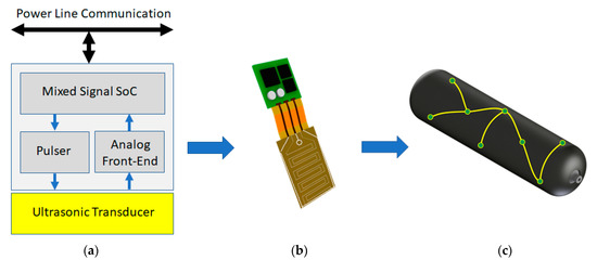
Figure 4. A wired sensor network based on autonomous sensor node design. In the example each node is equipped with ab ultrasonic transducer for active and passive ultrasonic guided waves (UGW) operation: (a) node electronic block scheme; (b) node rendering; and, (c) rendering of a possible application to a Composite Overwrapped Pressure Vessel (COPV) equipped with a wired sensor network.
Schubert et al. published one of the first implementation of this paradigm [69] with the Match-X project of the Fraunhofer Institute. The node design and electronic integration with a stack of miniaturized PCBs with embedded PZT transducers that were mounted on a glass-fiber-reinforced-polymer (GFRP) plate is reported. The paper also addressed the requirement of power supply overvoltage protection and detection of failure events that is one important consideration for self-diagnostic of nodes. Lehmann et al. [53] presented, in the same year, the results of validation of the embedded PZT MFC transducers in an aircraft wing. Local processing of the acoustic signatures was demonstrated by the integration of the AFE in the node architecture: the ADC, algorithms for data reduction, and digital communication by a Digital Signal Processor (DSP). Although the adopted solution for data transfer was based on a two wires industrial Controller Area Network (CAN) bus, the authors introduced an expandable feature to open the wireless connection with a Bluetooth module, a key feature for the evolution to a Wireless Sensor Network (WSN). Figure 5 shows the main electronic blocks of a sensor node for a WSN.
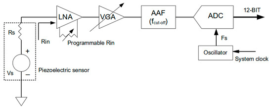
Figure 5. Programmable single channel AFE for signal conditioning of piezoelectric sensor.
3.1. Nodes and Modules with Low Power Electronics Solutions with Energy Harvesting
The main evolution for continuous impacts monitoring is the concept of autonomous nodes. In the case of an SHM system, we can observe that environmental operating conditions, like those described in Figure 1, are represented by different types of energy exchanges with the structure. This interaction from the point of view of the impact event capture is seen as a disturbance or noise, but from the point of view of local energy accumulation, can represent an opportunity.
A preliminary work testifying to this evolution was published by Champaigne et al. [70], describing a wirelessly connected SHM system to interface up to four PZT sensors and an AFE that was capable of matching with the characteristics of different types of sensors.
In that paper, low power electronics that were available at that time were adopted to be compatible with charge capacity of a dual AA-cell battery pack to reach an operational time up to 10 total hours. A consideration must be made about the careful choice done for digital electronics, such as the ADC, FPGA, and digital communication, which are typically power-hungry devices. A recent paper that can solve the power demands for continuous monitoring is proposed by Fu et al. [71], and the solution consists of keeping in a sleep mode a section of the digital electronic processing until a detected event switches on the power supply of the data acquisition and processing blocks; Overly et al. published a similar approach with a compact electronic design for a wireless smart sensor node [72]. The latter work used low power chips and self-diagnostic for the detection of PZT elements debonding from an aircraft wing. Another important design issue that is tackled in the paper is the temporal synchronization of data from an impact event that was detected by the WSN; this topic will be expanded in Section 5.2. The design of a WSN with low power budget obtained by the sleep mode operability is presented by Giannì et al. [73]; in particular, the authors analyze the design issues regarding the AFE + ADC noise characteristics and their influence on the errors achievable for impact positioning with a triangulation method.
Ferin et al. [74] presented a new hardware development of a highly versatile energy autonomous acoustic sensor node that is an element of an intelligent wireless network; this node architecture is capable of executing various ultrasonic inspection algorithms. The energy harvester was the conversion from mechanical vibrations into electrical energy stored in a supercapacitor with a high charge capacity/volume ratio. In this paper, the hardware specifications for an automated and remote aircraft ultrasound inspection were considered to be a start point for a product-oriented research. Taking advantage of low power electronics with energy harvesting solutions, the design of a MEMS piezoelectric power module converter with a power density of 6 mW/cm3/g2 and an output power around 120 μW was presented. To cover the full power supply demands of a sensor node, multiple MEMS power modules can be connected at the expense of an increased volume occupation. The piezoelectric energy harvester system was capable of charging a thin film battery (EFL700A39 from STM—700 μA/h 3.9 V). The topic of energy harvesting is strictly related to the design of autonomous sensor nodes and several review papers for the interested reader as Mateu et [75], Sodano et al. [76], and Trigona et al. [77], and an example of a small scale factor energy harvester device is reported in Figure 6. The authors presented in [78] a prototype system for delivering energy to SHM sensor nodes by microwave wireless energy transmission in the 10 GHz X-band. The energy harvesting for low power WSN with special emphasis on SMH application has also been reviewed by Park et al. [79]. Finally, the outcomes of a recent project that was dedicated to the energy harvesting methods for SHM systems installed on airplanes have been published by Zelenika et al. [80]. In [77] the authors presented a prototype system for delivering energy to SHM sensor nodes by microwave wireless energy transmission in the 10 GHz X-band. The energy harvesting for low power WSN with special emphasis on SMH application has been reviewed also by Park et al. [81]. Finally, the outcomes of a recent project dedicated on the energy harvesting methods for SHM systems installed on airplanes have been published by Zelenika et al. [82].
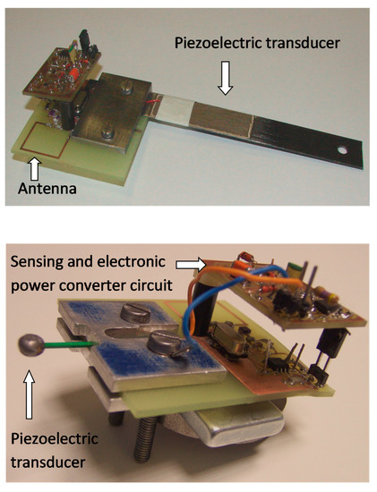
Figure 6. The realized prototype of the autonomous sensor module with a thick-film piezoelectric converter (top) and with a commercial piezoelectric converter (bottom) (adapted from [83] with authors permission).
It is also worth mentioning industrial projects covering the WSN approach for aircraft SHM as proposed by METIS Design company [84] and the European Project “FLite Instrumentation TEst Wireless Sensor” [85]. Smithard et al. presented another kind of sensor network formed by modules that were connected by fiber optics to obtain large immunity from environmental electromagnetic noise in [86]. The Acousto Ultrasonic Structural health monitoring Array Module (AUSAM) project relies on autonomous electronic modules that are designed with off-the-shelf electronic components that interface up to 62 PWAS. These modules can operate in active and passive mode, and they are also equipped with an EMI module; the latter is usefully adopted for checking the reliability of the PWASs. A futuristic vision of the AUSAM module is the transportation and installation on the structure by a drone, with some advantages for maintenance service performance and costs. A similar idea of using drones for EMI technique has been recently reported by Na et al. [87]. The interest of sensor networks for SHM in transportation and civil engineering infrastructures also requires a different approach for system performance evaluation; Ju et al. [88] proposed a simulation of a sensor network for the continuous monitoring of railroads, where fast transportation systems are in service. Sundaram et al. [89] reviewed the advantages of WSN for SHM of large civil engineering structures and pointed out the problem of connection reliability, obstructions to radio links, and, finally, the energy harvesting.
Ren et al. [90] presented a strategy for radio communication of autonomous nodes for impact monitoring of large structures and a preliminary validation on a laboratory mock-up of an air wing is presented. The original solution is the adoption of a multi-channel radio communication on different frequency channels to improve the data transmission capability and the reliability of the WSN. Embedded computational resources in sensors nodes for vibration monitoring has been designed and tested on a laboratory mock up by Testoni et al. [91]; this work shows a node design with volume/weight constraints and low power consumption for implementing a wired sensor network based on PCL. A dramatic gain in volume factor for integrated sensor node is achievable by integrated electronic design. With this approach, each electronic block (see Figure 7) can be optimized for low power consumption (oscillators, PWM, ADC, and wake/sleep-mode circuit) and more important the wireless transmission and power management. For the latter solutions based on low voltage single cell batteries are available connected with buck-boost DC-DC converters. The efficiency of these converters is high at low switching frequencies, but it requires an inductor-capacitor (L-C) tank with large component values, which implies a larger volume. Moreover, the integration of different types of transducers (optical, acoustic, and radiofrequency) on a small-scale can ensure the required average and peak power consumption. Lee et al. reported an example of recent development of the integrated custom electronic with multi-chip connection [92].
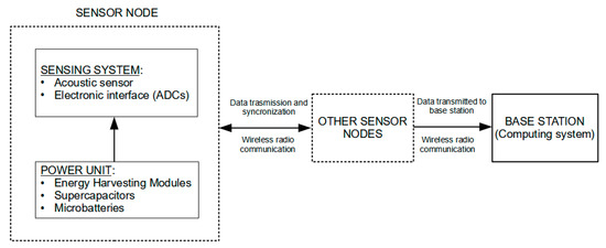
Figure 7. A block diagram of a wireless autonomous sensor network for SHM connected to a base station.
Summarizing the results of the works that are examined in this section, we can say that technologies for embedded signal processing, low power signal transmission, and their integration with energy harvester devices are now available and they have mainly been demonstrated with laboratory experiments, and some real life installations are featured in the literature. In the next section we will make a discussion of the issues for a wide spreading of smart nodes for SHM networks.
3.2. Toward SHM Sensor Networks with Smart Nodes
From the previous paragraph there is strong interest in moving the SHM system toward sensor networks and, in the following section, we will draw some general comments and challenges for addressing the next steps for new developments. In this section, we discuss the advancements of smart nodes in the perspective of an impact sensing SHM network.
The evaluation of data transfer requirements for a node is one of the topics that is now under development for the research. The reduction of data rate for a “smart-node” requires that some local processing is needed. The data rate reduction is achievable by compressive sensing techniques, as investigated by Mascarenas in [93]. The recent research on this subject also demonstrated the benefits for the autonomous detection and localization of an AE source, as we will explain later in Section 6.
The presence of smart sensor nodes, and a relatively dense interconnection network, can provide some degree of redundancy to the SHM system, where failing sensor nodes will not compromise the operation of the overall system. Of course, the thickening of the interconnection network goes against the minimum-encumbrance policy, which is one of the original goals of the sensor network architecture, but it is a trade-off that should, nonetheless, be considered. From the point of view of harnessing, PLC represents a way to achieve the minimum amount of cabling required to route the sensor network, albeit at the cost of reduced bandwidth. A problem that is deeply ingrained in sensor networks that need to cooperate in the ways described above is how to achieve and maintain inter-node synchronization. Although the topic has not been addressed so far, the problem of synchronization in measurement and control networks is well known and it will be approached starting from the provisions of the Precise Time Protocol (PTP) IEEE 1588 standard that can reach a synchronization accuracy of 0.1 µs wired network connected on ethernet. Such performance is compatible with SHM sensor network design being the UGW signals with the frequency content below 1 MHz and Time of Flight (TOF) in the order of 10 µs–100 µs. This analysis derives from the main requirement that each sensor node needs to be synchronized up to a fraction of the DToA to produce data that are useful for accurate impact positions. The synchronization problem is even more complex for WSNs and the next section will go in some detail of the proposed solutions.
3.3. WSN and IoT for SHM
In the last few years, the concept of WSN for SHM has moved on to the Internet of Things (IoT) for SHM. The main advantage of introducing the communication of a WSN for SHM over the Internet comes from the possibility to uniquely identify the data packet generated sensor node and the large bandwidth for data transmission; time correlation is achieved thanks to the accurate synchronization of nodes. In addition, the large storage capacity of the cloud allows for further implementing data interpretation using AI and deep learning for Big Data (BD); some examples of the latter novel development will be reported in the next section.
Tokognon et al. [94] have reviewed the challenges for the design SHM using IoT technologies well to achieve intelligent and reliable WSN for monitoring structures. The authors identify three main blocks to be integrated for this aim:
-
Sensing and data Acquisition Subsystem.
-
Data Management Subsystem: preprocessing methods used to organize raw data that were acquired from sensors and remove the noise before processing; novelty detection, classification, and regression approaches. Among them, novelty detection based on artificial neural networks.
-
Data Access and Retrieval Subsystem.
The requirement of low power communication technology based on the IPv6 assignment of a node is analyzed for battery operated sensors. The work of the ZigBee Alliance has accelerated the expansion of the sensor network and building automation market. From the PHY and MAC layers that are defined in the IEEE 802.15.4 standards, Zigbee considers the networking and services layer, through the full application layer. ZigBee PRO was specifically developed for device-to-device communication in an IoT context.
Unfortunately, WSN based on IEEE 802.15.4/ZigBee do not currently support IP, mainly due to the small length of packets that are used in IEEE 802.15.4. Therefore, most of the solutions proposed consist of using IP proxy or gateways. A network configuration strategy for WSN configuration with sink nodes at the edge of the network, also called border routers, with IP protocol connection over the Internet is presented in the paper by Tokognon et al. [94]. From the sink nodes, data can be transferred with JavaScript object notation (JSON) to a Web server, where a large storage capacity is commonly available.
Moreover, the Internet Engineering Task Force (IETF) defined the 6LoWPAN standard (RFC 4944) to allow the use of IPv6 packets over IEEE802.15.4 networks. The new compressed IP headers resolve the packets size issues and the fragmentation mechanism to transmit IP packets over IEEE802.15.4 networks. IETF also started a working group to evaluate the appropriate routing protocols for low-power (RPL) and lossy networks.
The node synchronization is another challenge for a distributed IoT, as stated in the previous section. Scuro et al. [95] published a paper that was devoted to this problem, and a solution was proposed with each node equipped with a clock; the nodesexchange synchronization messages to evaluate the frequency and the offset of their clock with respect to the one taken as a reference (master) or with respect to its neighbor sensor node. This solution implies an additional overhead, since extra messages and re-synchronization periods are required.
In the same structure, local area networks with routers that give priority to the transmission of the synchronization messages, or that compensate for the transmission delay, can be deployed. In these cases, a synchronization accuracy in the order of microseconds is still achievable. In fact, for the SHM system, the typical accuracy that is needed between the node is in the range [0.6, 9.0] μs. Muttillo et al. [96] presented a solution for structural monitoring with digital accelerometers ADXL355 with high resolution that was connected to hardware for IoT connection. A high synchronization between the sensors was implemented to preserve such performance.
Finally, Abdelgawad et al. [84] and Mahmud et al. [85] presented examples of prototype architectures for WSN nodes that were connected on ethernet based on Raspberry Pi. Besides the power consumption of these design was a neglected factor, the two systems were successfully demonstrated for SHM in a laboratory. Finally, an example of prototype architectures for WSN nodes connected on ethernet based on Raspberry Pi have been presented by Abdelgawad et al. [97] and Mahmud et al. [98]. Although the power consumption of these design was a neglected factor, the two systems were successfully demonstrated for SHM in laboratory.
This entry is adapted from the peer-reviewed paper 10.3390/s21092929
References
- Rose, J.L. Ultrasonic Guided Waves in Solid Media; Cambridge University Press: New York, NY, USA, 2014; ISBN 978-1-107-27361-0.
- Auld, B.A. Acoustic Fields and Waves in Solids; Wiley: New York, NY, USA, 1973; ISBN 978-0-471-03702-6.
- Farrar, C.R.; Worden, K. An Introduction to Structural Health Monitoring. Philos. Trans. R. Soc. Math. Phys. Eng. Sci. 2007, 365, 303–315.
- Farrar, C.R.; Worden, K. An Introduction to Structural Health Monitoring. In New Trends in Vibration Based Structural Health Monitoring; Deraemaeker, A., Worden, K., Eds.; CISM International Centre for Mechanical Sciences; Springer: Vienna, Austria, 2010; Volume 520, pp. 1–17. ISBN 978-3-7091-0398-2.
- Farrar, C.R.; Worden, K. Structural Health Monitoring: A Machine Learning Perspective; John Wiley & Sons, Ltd.: Chichester, UK, 2012; ISBN 978-1-118-44311-8.
- Mitra, M.; Gopalakrishnan, S. Guided Wave Based Structural Health Monitoring: A Review. Smart Mater. Struct. 2016, 25, 053001.
- Giurgiutiu, V. Structural Health Monitoring with Piezoelectric Wafer Active Sensors, 2nd ed.; Academic Press, an Imprint of Elsevier: Amsterdam, The Netherlands, 2014; ISBN 978-0-12-418691-0.
- Zhou, G.; Sim, L.M. Damage Detection and Assessment in Fibre-Reinforced Composite Structures with Embedded Fibre Optic Sensors-Review. Smart Mater. Struct. 2002, 11, 925–939.
- Kirkby, E.; de Oliveira, R.; Michaud, V.; Månson, J.A. Impact Localisation with FBG for a Self-Healing Carbon Fibre Composite Structure. Compos. Struct. 2011, 94, 8–14.
- Shin, C.S.; Chen, B.L. An Impact Source Locating System Using Fiber Bragg Grating Rosette Array. In Proceedings of the Third International Conference on Smart Materials and Nanotechnology in Engineering, Shenzhen, China, 2 April 2012; p. 84091B.
- Yeager, M.; Whittaker, A.; Todd, M.; Kim, H.; Key, C.; Gregory, W. Impact Detection and Characterization in Composite Laminates with Embedded Fiber Bragg Gratings. Procedia Eng. 2017, 188, 156–162.
- Datta, A.; Augustin, M.J.; Gupta, N.; Viswamurthy, S.R.; Gaddikeri, K.M.; Sundaram, R. Impact Localization and Severity Estimation on Composite Structure Using Fiber Bragg Grating Sensors by Least Square Support Vector Regression. IEEE Sens. J. 2019, 19, 4463–4470.
- Roach, D.P. FAA Research Program Webinar Series on Structural Health Monitoring—Module 1: Introduction to SHM and Implementation. 2016. Available online: (accessed on 20 April 2021).
- Shen, G.; Zhang, J.; Lackner, G. International Acoustic Emission Standard Analysis and Development Outlook. Insight Non-Destr. Test. Cond. Monit. 2020, 62, 724–734.
- Staszewski, W.J.; Boller, C.; Tomlinson, G.R. Health Monitoring of Aerospace Structures: Smart Sensor Technologies and Signal Processing; Staszewski, W.J., Boller, C., Tomlinson, G.R., Eds.; Wiley: Hoboken, NJ, USA; West Sussex, UK, 2004; ISBN 978-0-470-84340-6.
- Staszewski, W.J. Structural Health Monitoring Using Guided Ultrasonic Waves. In Advances in Smart Technologies in Structural Engineering; Computational Methods in Applied Sciences; Holnicki-Szulc, J., Soares, C.M., Eds.; Springer: Berlin/Heidelberg, Germany, 2004; Volume 1, pp. 117–162. ISBN 978-3-642-06104-2.
- Wilcox, P. Application of Guided Wave Signal Processing to Acoustic Emission Data. In AIP Conference Proceedings; AIP: Golden, CO, USA, 2005; Volume 760, pp. 1809–1816.
- Giurgiutiu, V. Structural Health Monitoring with Piezoelectric Wafer Active Sensors, 1st ed.; Academic Press: Amsterdam, The Netherlands; Boston, MA, USA, 2008; ISBN 978-0-12-088760-6.
- Ultrasonic Guided Waves; Lissenden, C.J. (Ed.) MDPI: Basel, Switzerland, 2020; ISBN 978-3-03928-299-9.
- Ono, K. Review on Structural Health Evaluation with Acoustic Emission. Appl. Sci. 2018, 8, 958.
- Rose, J. Ultrasonic Guided Waves in Structural Health Monitoring. Key Eng. Mater. 2004, 270–273, 14–21.
- Mallardo, V.; Aliabadi, M.H. Optimal Sensor Placement for Structural, Damage and Impact Identification: A Review. SDHM Struct. Durab. Health Monit. 2013, 9, 287–323.
- Safri, S.; Sultan, M.T.H.; Yidris, N.; Mustapha, F. Low Velocity and High Velocity Impact Test on Composite Materials—A Review. Int. J. Eng. Sci. 2014, 3, 50–60.
- Ross, R. Structural Health Monitoring and Impact Detection Using Neural Networks for Damage Characterization. In Proceedings of the 47th AIAA/ASME/ASCE/AHS/ASC Structures, Structural Dynamics, and Materials, Newport, RI, USA, 1–4 May 2006; Volume 9.
- Tobias, A. Acoustic-Emission Source Location in Two Dimensions by an Array of Three Sensors. Non-Destr. Test. 1976, 9, 9–12.
- Ziola, S.M.; Gorman, M.R. Source Location in Thin Plates Using Cross-correlation. J. Acoust. Soc. Am. 1991, 90, 2551–2556.
- Marino-Merlo, E.; Bulletti, A.; Giannelli, P.; Calzolai, M.; Capineri, L. Analysis of Errors in the Estimation of Impact Positions in Plate-Like Structure through the Triangulation Formula by Piezoelectric Sensors Monitoring. Sensors 2018, 18, 3426.
- Gorman, M.R.; Humes, D.H.; June, R.; Prosser, W.H.; Prosser, W.H. Acoustic Emission Signals in Thin Plates Produced by Impact Damage. J. Acoust. Emiss. 1999, 17, 29–36.
- Yang, J.C.S.; Chun, D.S. Application of the Hertz Contact Law to Problems of Impact in Plates; Defense Technical Information Center: Fort Belvoir, WV, USA, 1969.
- Richardson, M. Measurement and Analysis of the Dynamics of Mechanical Structures. J. Acoust. Soc. Am. 1979, 65, S77.
- Staszewski, W.J.; Mahzan, S.; Traynor, R. Health Monitoring of Aerospace Composite Structures—Active and Passive Approach. Compos. Sci. Technol. 2009, 69, 1678–1685.
- Lamb, H. On Waves in an Elastic Plate. Proc. R. Soc. Lond. Ser. Contain. Pap. Math. Phys. Character 1917, 93, 114–128.
- Bulletti, A.; Merlo, E.M.; Capineri, L. Analysis of the Accuracy in Impact Localization Using Piezoelectric Sensors for Structural Health Monitoring with Multichannel Real-Time Electronics. In Proceedings of the 2020 IEEE 7th International Workshop on Metrology for AeroSpace (MetroAeroSpace), Virtual Conference, Pisa, Italy, 22–24 June 2020; pp. 480–484.
- Chandrasekaran, S. Structural Health Monitoring with Application to Offshore Structures; World Scientific: Singapore, 2019; ISBN 9789811201080.
- Miniaci, M.; Mazzotti, M.; Radzieński, M.; Kudela, P.; Kherraz, N.; Bosia, F.; Pugno, N.M.; Ostachowicz, W. Application of a Laser-Based Time Reversal Algorithm for Impact Localization in a Stiffened Aluminum Plate. Front. Mater. 2019, 6, 30.
- Nicassio, F.; Carrino, S.; Scarselli, G. Non-Linear Lamb Waves for Locating Defects in Single-Lap Joints. Front. Built Environ. 2020, 6, 45.
- Mevissen, F.; Meo, M. A Nonlinear Ultrasonic Modulation Method for Crack Detection in Turbine Blades. Aerospace 2020, 7, 72.
- Fink, M. Time Reversal Mirrors. In Acoustical Imaging; Jones, J.P., Ed.; Acoustical Imaging; Springer: Boston, MA, USA, 1995; Volume 21, pp. 1–15. ISBN 978-1-4613-5797-1.
- Zeng, L.; Lin, J.; Huang, L. A Modified Lamb Wave Time-Reversal Method for Health Monitoring of Composite Structures. Sensors 2017, 17, 955.
- Wilcox, P.; Lowe, M.J.S.; Cawley, P. Effect of Dispersion on Long-Range Inspection Using Ultrasonic Guided Waves. NDT E Int. 2001, 34, 1–9.
- Sanderson, R. A Closed Form Solution Method for Rapid Calculation of Guided Wave Dispersion Curves for Pipes. Wave Motion 2015, 53, 40–50.
- Zhong, Y.; Xiang, J.; Gao, H.; Zhou, Y. Impact Energy Level Assessment of Composite Structures Using MUSIC-ANN Approach: MUSIC-ANN Approach-Based Impact Monitoring for Composite Structures. Struct. Control Health Monit. 2016, 23, 825–837.
- Engholm, M.; Stepinski, T. Direction of Arrival Estimation of Lamb Waves Using Circular Arrays. Struct. Health Monit. 2011, 10, 467–480.
- Zhong, Y.; Xiang, J.; Chen, X.; Jiang, Y.; Pang, J. Multiple Signal Classification-Based Impact Localization in Composite Structures Using Optimized Ensemble Empirical Mode Decomposition. Appl. Sci. 2018, 8, 1447.
- Mariani, S.; Liu, Y.; Cawley, P. Improving Sensitivity and Coverage of Structural Health Monitoring Using Bulk Ultrasonic Waves. Struct. Health Monit. 2020, 147592172096512.
- Mariani, S.; Heinlein, S.; Cawley, P. Location Specific Temperature Compensation of Guided Wave Signals in Structural Health Monitoring. IEEE Trans. Ultrason. Ferroelectr. Freq. Control 2020, 67, 146–157.
- Sepehry, N.; Shamshirsaz, M.; Abdollahi, F. Temperature Variation Effect Compensation in Impedance-Based Structural Health Monitoring Using Neural Networks. J. Intell. Mater. Syst. Struct. 2011, 22, 1975–1982.
- Qing, X.; Li, W.; Wang, Y.; Sun, H. Piezoelectric Transducer-Based Structural Health Monitoring for Aircraft Applications. Sensors 2019, 19, 545.
- De Simone, M.E.; Ciampa, F.; Boccardi, S.; Meo, M. Impact Source Localisation in Aerospace Composite Structures. Smart Mater. Struct. 2017, 26, 125026.
- Seno, A.H.; Aliabadi, M.F. Impact Localisation in Composite Plates of Different Stiffness Impactors under Simulated Environmental and Operational Conditions. Sensors 2019, 19, 3659.
- Kundu, T.; Das, S.; Jata, K.V. Point of Impact Prediction in Isotropic and Anisotropic Plates from the Acoustic Emission Data. J. Acoust. Soc. Am. 2007, 122, 2057–2066.
- Hakoda, C.; Lissenden, C. Using the Partial Wave Method for Wave Structure Calculation and the Conceptual Interpretation of Elastodynamic Guided Waves. Appl. Sci. 2018, 8, 966.
- Lehmann, M.; Büter, A.; Frankenstein, B.; Schubert, F.; Brunner, B. Monitoring System for Delamination Detection—Qualification of Structural Health Monitoring (SHM) Systems. In Proceedings of the Conference on Damage in Composite Material CDCM, Stuttgart, Germany, 18–19 September 2006.
- Scheerer, M.; Lager, D. Development and Testing of a Hybride Active—Passive Acoustic Shm System for Impact Damage Detection in Honeycomb Aircraft Structures. In Proceedings of the 19th ICCM, Montreal, QC, Canada, 28 July–2 August 2013.
- Ebrahimkhanlou, A.; Salamone, S. Acoustic Emission Source Localization in Thin Metallic Plates: A Single-Sensor Approach Based on Multimodal Edge Reflections. Ultrasonics 2017, 78, 134–145.
- Park, W.H.; Packo, P.; Kundu, T. Acoustic Source Localization in an Anisotropic Plate without Knowing Its Material Properties—A New Approach. Ultrasonics 2017, 79, 9–17.
- Ren, B.; Lissenden, C.J. PVDF Multielement Lamb Wave Sensor for Structural Health Monitoring. IEEE Trans. Ultrason. Ferroelectr. Freq. Control 2016, 63, 178–185.
- Altammar, H.; Dhingra, A.; Salowitz, N. Ultrasonic Sensing and Actuation in Laminate Structures Using Bondline-Embedded D35 Piezoelectric Sensors. Sensors 2018, 18, 3885.
- Ciampa, F.; Meo, M. A New Algorithm for Acoustic Emission Localization and Flexural Group Velocity Determination in Anisotropic Structures. Compos. Part Appl. Sci. Manuf. 2010, 41, 1777–1786.
- Kundu, T. Acoustic Source Localization. Ultrasonics 2014, 54, 25–38.
- Marchi, L.D.; Marzani, A.; Speciale, N.; Viola, E. A Passive Monitoring Technique Based on Dispersion Compensation to Locate Impacts in Plate-like Structures. Smart Mater. Struct. 2011, 20, 035021.
- Si, L.; Baier, H. Real-Time Impact Visualization Inspection of Aerospace Composite Structures with Distributed Sensors. Sensors 2015, 15, 16536–16556.
- Scholey, J.; Wilcox, P.; Wisnom, M.; Friswell, M.; Pavier, M.J.; Aliha, M.R.M. A Generic Technique for Acoustic Emission Source Location. J Acoust. Emis. 2009, 27, 291–298.
- Morón, C.; Portilla, M.; Somolinos, J.; Morales, R. Low-Cost Impact Detection and Location for Automated Inspections of 3D Metallic Based Structures. Sensors 2015, 15, 12651–12667.
- Nucera, C.; White, S.; Chen, Z.M.; Kim, H.; Lanza di Scalea, F. Impact Monitoring in Stiffened Composite Aerospace Panels by Wave Propagation. Struct. Health Monit. Int. J. 2015, 14, 547–557.
- Farrar, C.R.; Park, G.; Todd, M.D. Sensing Network Paradigms for Structural Health Monitoring. In New Developments in Sensing Technology for Structural Health Monitoring; Mukhopadhyay, S.C., Ed.; Lecture Notes in Electrical Engineering; Springer: Berlin/Heidelberg, Germany, 2011; Volume 96, pp. 137–157. ISBN 978-3-642-21098-3.
- Qiu, L.; Deng, X.; Yuan, S.; Huang, Y.; Ren, Y. Impact Monitoring for Aircraft Smart Composite Skins Based on a Lightweight Sensor Network and Characteristic Digital Sequences. Sensors 2018, 18, 2218.
- Giannelli, P.; Bulletti, A.; Granato, M.; Frattini, G.; Calabrese, G.; Capineri, L. A Five-Level, 1-MHz, Class-D Ultrasonic Driver for Guided-Wave Transducer Arrays. IEEE Trans. Ultrason. Ferroelectr. Freq. Control 2019, 66, 1616–1624.
- Schubert, L.; Frankenstein, B.; Reppe, G. Match-X Based Microsystem for Structural Health Monitoring. In Proceedings of the 2006 1st Electronic Systemintegration Technology Conference, Dresden, Germany, 5–7 September 2006; pp. 635–641.
- Champaigne, K.D.; Sumners, J. Low-power Electronics for Distributed Impact Detection and Piezoelectric Sensor Applications. In Proceedings of the 2007 IEEE Aerospace Conference, Big Sky, MT, USA, 3–10 March 2007.
- Fu, H.; Sharif Khodaei, Z.; Aliabadi, M.H.F. An Event-Triggered Energy-Efficient Wireless Structural Health Monitoring System for Impact Detection in Composite Airframes. IEEE Internet Things J. 2019, 6, 1183–1192.
- Overly, T.G.S.; Park, G.; Farinholt, K.M.; Farrar, C.R. Development of an Extremely Compact Impedance-Based Wireless Sensing Device. Smart Mater. Struct. 2008, 17, 065011.
- Giannì, C.; Balsi, M.; Esposito, S.; Ciampa, F. Low-power Global Navigation Satellite System-enabled Wireless Sensor Network for Acoustic Emission Localisation in Aerospace Components. Struct. Control Health Monit. 2020, 27, 1–13.
- Ferin, G.; Muralidharan, Y.; Mesbah, N.; Chatain, P.; Bantignies, C.; Le Khanh, H.; Flesch, E. Smart Autonomous Wireless Acoustic Sensors for Aeronautical SHM Applications. In Proceedings of the 2015 IEEE International Ultrasonics Symposium (IUS), Taipei, Taiwan, 21–24 October 2015; pp. 1–4.
- Mateu, L.; Moll, F. Review of Energy Harvesting Techniques and Applications for Microelectronics (Keynote Address). In Volume 5837, VLSI Circuits and Systems II; Lopez, J.F., Fernandez, F.V., Lopez-Villegas, J.M., de la Rosa, J.M., Eds.; SPIE: Bellingham, WA, USA, 2005; pp. 359–373.
- Sodano, H.A.; Inman, D.J.; Park, G. A Review of Power Harvesting from Vibration Using Piezoelectric Materials. Shock Vib. Dig. 2004, 36, 197–205.
- Ferrari, M.; Ferrari, V.; Guizzetti, M.; Andò, B.; Baglio, S.; Trigona, C. Improved Energy Harvesting from Wideband Vibrations by Nonlinear Piezoelectric Converters. Sens. Actuators Phys. 2010, 162, 425–431.
- Muralt, P.; Kholkin, A.; Kohli, M.; Maeder, T. Piezoelectric Actuation of PZT Thin-Film Diaphragms at Static and Resonant Conditions. Sens. Actuators Phys. 1996, 53, 398–404.
- Bernstein, J.J.; Finberg, S.L.; Houston, K.; Niles, L.C.; Chen, H.D.; Cross, L.E.; Li, K.K.; Udayakumar, K. Micromachined High Frequency Ferroelectric Sonar Transducers. IEEE Trans. Ultrason. Ferroelectr. Freq. Control 1997, 44, 960–969.
- Feng, G.-H.; Chen, W.-M. Micromachined Lead Zirconium Titanate Thin-Film-Cantilever-Based Acoustic Emission Sensor with Poly(N-Isopropylacrylamide) Actuator for Increasing Contact Pressure. Smart Mater. Struct. 2016, 25, 055046.
- Park, G.; Farinholt, K.M.; Farrar, C.R.; Rosing, T.; Todd, M.D. Powering Wireless SHM Sensor Nodes through Energy Harvesting. In Energy Harvesting Technologies; Priya, S., Inman, D.J., Eds.; Springer: Boston, MA, USA, 2009; pp. 493–506. ISBN 978-0-387-76463-4.
- Zelenika, S.; Hadas, Z.; Bader, S.; Becker, T.; Gljušćić, P.; Hlinka, J.; Janak, L.; Kamenar, E.; Ksica, F.; Kyratsi, T.; et al. Energy Harvesting Technologies for Structural Health Monitoring of Airplane Components—A Review. Sensors 2020, 20, 6685.
- Ferrari, M.; Ferrari, V.; Guizzetti, M.; Marioli, D. An Autonomous Battery-Less Sensor Module Powered by Piezoelectric Energy Harvesting with RF Transmission of Multiple Measurement Signals. Smart Mater. Struct. 2009, 18, 085023.
- Available online: (accessed on 20 April 2021).
- Available online: (accessed on 20 April 2021).
- Smithard, J.; Norman, P.; van der Velden, S.; Powlesland, I.; Jung, G.; Rajic, N.; Galea, S. The Acousto Ultrasonic Structural Health Monitoring Array Module (AUSAM+) for Damage Detection in Structures. Procedia Eng. 2017, 188, 448–455.
- Na, W.; Baek, J. A Review of the Piezoelectric Electromechanical Impedance Based Structural Health Monitoring Technique for Engineering Structures. Sensors 2018, 18, 1307.
- Ju, Z.; Li, F.; Janapati, V.; Chung, H.; Yadav, S.; Cheung, C. Sensor Network Design Technique for Monitoring Railroad Structures. In Proceedings of the 1st International Workshop on Structural Health Monitoring for Railway Systems, Qingdao, China, 12–14 October 2016.
- Sundaram, B.A.; Ravisankar, K.; Senthil, R.; Parivallal, S. Wireless Sensors for Structural Health Monitoring and Damage Detection Techniques. Curr. Sci. 2013, 104, 1496–1505.
- Ren, Y.; Yuan, S.; Qiu, L.; Mei, H. Impact Localization by a Multi-Radio Sink–Based Wireless Sensor Network for Large-Scale Structures. Adv. Struct. Eng. 2017, 20, 157–169.
- Testoni, N.; Aguzzi, C.; Arditi, V.; Zonzini, F.; De Marchi, L.; Marzani, A.; Cinotti, T.S. A Sensor Network with Embedded Data Processing and Data-to-Cloud Capabilities for Vibration-Based Real-Time SHM. J. Sens. 2018, 2018, 2107679.
- Lee, Y.; Blaauw, D.; Sylvester, D. Ultralow Power Circuit Design for Wireless Sensor Nodes for Structural Health Monitoring. Proc. IEEE 2016, 104, 1529–1546.
- Mascareñas, D.; Cattaneo, A.; Theiler, J.; Farrar, C. Compressed Sensing Techniques for Detecting Damage in Structures. Struct. Health Monit. Int. J. 2013, 12, 325–338.
- Arcadius Tokognon, C.; Gao, B.; Tian, G.Y.; Yan, Y. Structural Health Monitoring Framework Based on Internet of Things: A Survey. IEEE Internet Things J. 2017, 4, 619–635.
- Scuro, C.; Sciammarella, P.F.; Lamonaca, F.; Olivito, R.S.; Carni, D.L. IoT for Structural Health Monitoring. IEEE Instrum. Meas. Mag. 2018, 21, 4–14.
- Muttillo, M.; Stornelli, V.; Alaggio, R.; Paolucci, R.; Di Battista, L.; de Rubeis, T.; Ferri, G. Structural Health Monitoring: An IoT Sensor System for Structural Damage Indicator Evaluation. Sensors 2020, 20, 4908.
- Abdelgawad, A.; Yelamarthi, K. Internet of Things (IoT) Platform for Structure Health Monitoring. Wirel. Commun. Mob. Comput. 2017, 2017, 1–10.
- IEEE Staff. 2018 IEEE 4th World Forum on Internet of Things (WF IoT); IEEE: Piscataway, NJ, USA, 2018; ISBN 978-1-4673-9945-6.