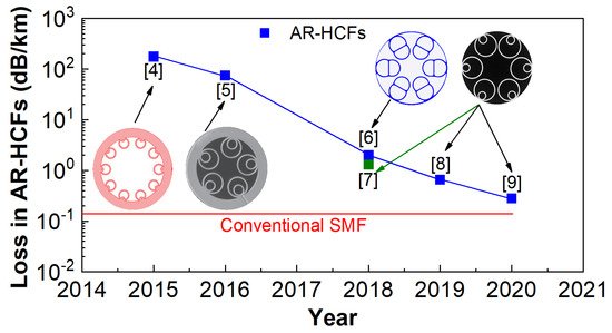
Specialty fibers have enabled a wide range of sensing applications. Particularly, with the recent advancement of anti-resonant effects, specialty fibers with hollow structures offer a unique sensing platform to achieve highly accurate and ultra-compact fiber optic sensors with large measurement ranges. Enabled by the specialty fiber manufacturing industry, AR-HCFs have shown great potential in optical fiber communication and sensing. AR-HCFs have very low transmission loss, optical nonlinearity, and chromatic dispersion over a broad bandwidth. They also have intrinsic advantages of high sensitivity, compact structures, and robust operation. All these remarkable advantages promote diversified sensing applications of AR-HCF. As a functionalized device, it has been extensively used for common parameter sensing, including solid, gas, and liquid.
- specialty fiber
- anti-resonant effect
- hollow structure
- sensing applications
1. Background
2. Principle and Various Structure of AR-HCFs
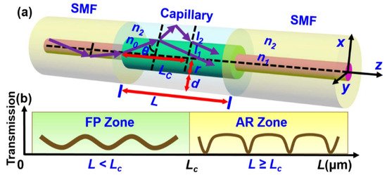
2.1. Principle of Light Propagation in AR-HCFs
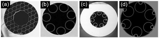
2.2. Various Structures of AR-HCFs
| Type | Core Diameter | Silica Thickness | Transmission Loss | Reference |
|---|---|---|---|---|
| Densely arrangement |
45.8 μm | 0.51 μm | 300 dB/km | [15] |
| 50 μm | 0.28 μm | 180 dB/km | [16] | |
| 60 μm | 1.4 μm | 17 dB/km | [18] | |
| Suspended capillary tubes |
30 μm | 0.44 μm | 180 dB/km | [19] |
| 30 μm | 0.83 μm | 30 dB/km | [21] | |
| 41 μm | 0.545 μm | 7.7 dB/km | [26] | |
| Nested Suspended tubes |
25 μm | 2.3 μm | 75 dB/km | [5] |
| ~33 μm | ~0.78 μm | 2 dB/m | [31] | |
| ~35 μm | ~0.5 μm | 6.6 dB/km | [32] |
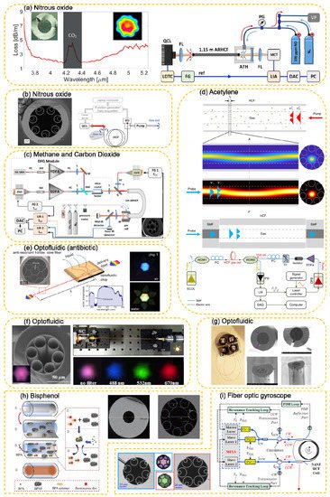
3. AR-HCF-Based Sensing Applications
3.1. Special Device-Based Sensing Applications
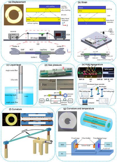
3.2. Versatile Platform Based Sensing Applications
This entry is adapted from the peer-reviewed paper 10.3390/photonics8040128