Your browser does not fully support modern features. Please upgrade for a smoother experience.
Please note this is an old version of this entry, which may differ significantly from the current revision.
Subjects:
Others
Building microfluidic Brain-on-a-Chip (BoC) models from the ground-up will allow for research questions to be answered more thoroughly in the brain research field, but the design of these devices requires several choices to be made throughout the design development phase. These considerations include the cell types, extracellular matrix (ECM) material(s), and perfusion/flow considerations. Choices made early in the design cycle will dictate the limitations of the device and influence the end-point results such as the permeability of the endothelial cell monolayer, and the expression of cell type-specific markers.
- brain-on-a-chip
- microfluidics
- extracellular matrix
- basement membrane
- endothelial cells
- astrocytes
- pericytes
- neurons
1. Introduction
In recent years, progress toward understanding human brain physiology and disease mechanisms has been advanced using animal models, and in vitro studies. The most common animal models are rodents, which are either studied as a whole animal or through use of primary cells harvested for in vitro studies. Mouse models are particularly appealing due to their low cost and the repertoire of genetically engineered strains for studying disease [1]. While there are efforts to “humanize” mouse models to make them more relevant to study human disease, a major limitation is that rodents do not naturally develop diseases seen in humans, and thus they are unable to recapitulate the complex series of events leading to pathologies such as Alzheimer’s disease. The human and murine brain also differ considerably in the proportion of gray:white matter, regional organization and gene expression [2]. The species-based limitations that accompany animal models have led to the widespread use of human-based in vitro models for exploring disease mechanisms and therapeutic development.
Human brain tissues can be modeled in vitro using organoids, where human induced pluripotent stem cells (iPSCs) or embryonic cells are differentiated into neural cell types that mimic the brain physiology in a 3D structure [3]. Neural organoids have become common tools for researching brain development and disease, with a focus on either localized regions or the complex interactions that occur between brain regions [4]. Unfortunately, using organoids for late-stage disease modeling is limited by nutrient and oxygen diffusion into the 3D structure, and incorporating functional vasculature into organoids is an ongoing area of exploration [5]. These limitations have influenced in vitro models to move towards a more controlled microenvironment such as brain-on-chip (BoC) models, where brain cells can be patterned to resemble the brain architecture and nutrients can be circulated throughout a microfluidic channel to mimic vascularization.
Transitioning from a relatively simple 2D monolayer culture—supported by widely available liquid handling and imaging systems—to a 3D microfluidic BoC model is more labor-intensive and costly. However, 3D models are capable of recapitulating important aspects of physiology, including flow over endothelial cells, and the space for neuronal and astrocytic projections. Further, this development can be made with relatively common materials, as the ability to pattern complex structures using soft lithography enables microenvironments to be compatible with a flow system by incorporating channels and ports into elastomeric materials such as polydimethylsiloxane (PDMS) polymers [6].
Recent advances in the development of microfluidic BoC devices and biological research have shed light on the importance of shear stress exerted on endothelial cells, substrate stiffness, and cell-to-cell contact for inducing the physiology that is observed in vivo. For example, BoC models have shown that shear stress exerted against brain microvascular endothelial cells (BMECs) plays a role in upregulating adherens and tight junction proteins [7], and modulating expression of blood–brain barrier (BBB) markers such as claudin-5 and glucose transporter 1 (GLUT-1) [8]. Several independent lines of evidence suggest that shear stress does not change BMEC morphology [9,10], but rather tightens the barrier; most often evaluated using trans-endothelial electrical resistance (TEER) and permeability assays [11]. Additionally, recent 2D in vitro studies have demonstrated that substrate stiffness plays a role in BMEC tight junction integrity as well as astrocyte and neuron morphology [12,13,14]. Transwell assays have also demonstrated the importance of cell-to-cell contact on BBB integrity, as several studies have shown that coculture of BMEC with astrocytes and pericytes can increase TEER and permeability measures [15]. Together, these findings suggest that contextual cues are critical when mimicking complex microenvironments such as the human brain. Throughout this review, we will outline recent advances in BoC models, as well as provide an overview of factors to consider when developing a BoC device (Figure 1).
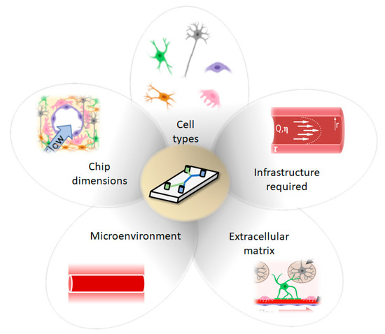
Figure 1. Considerations for development of Brain-on-a-Chip (BoC) models include cell types, chip dimension (2D, 2.5D, 3D), infrastructure required, ECM and microenvironment.
2. BoC Development
Advancing from a static 2D well-plate or Transwell experiment to a complex engineered platform that incorporates flow, requires careful initial consideration. Limitations of current models are discussed, so that new developments of BoC devices can aim to improve physiological relevance by selecting cell types, ECM, and a microenvironment that are similar to the brain in vivo. In this section, we will highlight the main considerations that are needed to build BoC devices, as well as highlight some of the current state-of-the-art BoC platforms and their limitations. To initiate development of a microfluidic BoC platform, the system requirements should be understood. The major initial considerations for BoC modeling include determining the region of interest within the brain and the corresponding vascular shear stress in that region. This will influence the BoC geometry and the pump specifications (syringe or peristaltic) needed to incorporate flow into the system. To decide on flow rate and BoC dimensions, the appropriate shear stress equation should be used. For instance, for a rigid, uniform, cylindrical vessel, the shear stress (τ) at the vessel wall can be derived from Poisseuille’s law to become:
where Q is the flow rate, η is the viscosity, and r is the radius of the vessel (Figure 2).
τ = 4Q *η/πr3
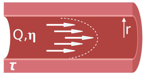
Figure 2. Parabolic shear stress profile in a blood vessel.
For example, to achieve a capillary-like shear stress of 1 dyn/cm2 [16] using a vessel with a radius of 100 μm, and standard cell media composition (Dulbecco’s Modified Eagle Medium (DMEM)) supplemented with 10% fetal bovine serum (FBS), which has a viscosity of ~0.93 mPa*s [17], then an approximate flow rate of 304 μL/hr would be required. However, if investigations lead to capillary vessel diameter changes, as seen with pericyte-mediated contractility, then adjusting the flow rate to obtain the desired shear stress may be needed [18]. To mimic blood flow in the brain, a continuous, unidirectional flow system is desirable to achieve physiological relevance. However, the concentration of soluble substances will be diluted as a function of flow rate and, at high flow rates, may fall below the detection limit of quantitative measures such as enzyme-linked immunosorbent assay (ELISA). Use of a peristaltic pump to continuously circulate fluid throughout the system may improve end-point analyses, as analytes would become concentrated in the circulating media.
During the prototyping stage, microfluidic chips are often fabricated using polydimethylsiloxane (PDMS). PDMS is a transparent, biocompatible, oxygen-permeable polymer that can be easily molded into high resolution geometries [6]. Creating a negative mold pattern is often performed using photolithography with a UV-sensitive material, patterning the silicon wafer with high resolution features in the micron range [19]. More recently, lower cost, 3D printed molds have been used to fabricate geometries in the range of hundreds of microns [20]. Alternative fabrication materials may be desirable, such as thermoplastic or polyester elastomers, if optical clarity or low adsorption is essential, although this will likely increase the cost per chip and affect the ease of fabrication [21]. Thermoset polymers such as SU-8 and thermoplastic polymers such as PMMA, polystyrene, and polytetrafluorethylene have also been used in microfluidic devices with improved solvent resistance, reduced small molecule adsorption, and improved rigidity compared to PDMS [22]. Teflon microfluidic chips, which will not adsorb small molecules, have been made using thermal compression [23], and PMMA chips have been made by thermal compression or laser micromachining. For research use, PDMS prototypes represent a reasonable compromise between the ease of production and low cost with performance of the device. The drawbacks of small molecule adsorption can be overcome with a coating on the PDMS or other postprocessing step. For commercial high volume manufacturing, the reliability that can be offered by other polymers such as polystyrene will become more important, and economy of scale justifies the investment in injection molding of polystyrene chips.
Throughout this review, we will be classifying 2D, 2.5D and 3D BoCs based on their microfluidic chip architectures. We will term models that have ECs, astrocytes and pericytes as BBB BoCs and models that include ECs, astrocytes, pericytes and neurons as a neurovascular unit (NVU) BoCs (Figure 3). Depending on the cell types included in the model, consideration should be given to the extracellular matrix (ECM), which is a key component of the brain microenvironment that must be incorporated into BoC models to recapitulate physiological phenotypes. These considerations will be covered in subsequent sections, following an overview of the advances and limitations of existing BoC designs.
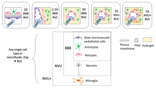
Figure 3. Dimensions of BoC devices. BoC devices can range from 2D, 2.5D, 3D with specific cell types to model BBB (EC, pericytes, astrocytes) or NVU (EC, pericytes, astrocytes, neurons).
Planar cell layers (2D) are amenable to simple fabrication processes and are the easiest transition from a static 2D model. The design of a 2D microfluidic BoC typically includes two compartments separated by a permeable membrane permitting cell–cell interaction, where at least one compartment acts as a flow channel to mimic vascular blood flow [11,24]. Commonly used membrane materials include polycarbonate (PC), polyester (PET) and PDMS membranes. In previous 2D BoC microfluidic models, PET and PC membranes were cut out of Transwell inserts to use in microfluidic BoCs [25]. More recently, commercially available track-etched PET and PC A4 sheets have been used [26,27]. To bond porous membranes to PDMS to obtain a leak-free channel, spin-coating PDMS [28], aminosilanization [29] or custom bonding procedures [30] may need to be performed. Furthermore, porous membranes such as PDMS will need further treatment to achieve the hydrophilicity required for adherence of ECM coatings [31]. The pore size and thickness of the porous membrane should be selected based on the application, as contact of astrocytes and pericytes with the endothelial cell monolayer will influence BBB function [32], thus larger pore sizes (~3 μm) should be considered to enable contact and increase fidelity to the native BBB anatomy. Commercially available microfluidic chip options such as the Emulate platform use a PDMS chip with 7.0 μm pore size in the membrane separating the channels [33]. Another important consideration in a 2D model is the ECM coating used on the membrane to mimic the microenvironment of the human brain basement membrane. Recent studies have explored the effect of ECM composition on endothelial cell tight junction properties [34], as well as permeability in Transwell inserts [35]. However, there are limited investigations into ECM coatings appropriate for coculture and tricultures in 2D environments that incorporate flow. Further exploration into ECM coatings used for BBB models will strengthen the robustness of 2D BoC models and potentially provide reliable environments to establish in vivo-like cellular functions and gene expression.
In this review, the term 2.5D model is used to describe endothelial cells forming a flat 2D monolayer around a rectangular channel that contains a 3D matrix [36]. 2.5D models are often used to recapitulate the architecture of the brain parenchyma by using a parallel channel design containing a hydrogel in one channel and flow across endothelial cells in the other channel. This design uses pillars to create distinctions between channels, so that a hydrogel can be flowed into the channel and cured using thermal gelation, photocrosslinking or chemical crosslinking methods. A 2.5D design allows brain cells to migrate towards the endothelium through a hydrogel to provide direct cell-to-cell contact as an artificial membrane is not required [37]. Having a planar 2.5D model will also improve imaging, since the media supply is parallel to the cells, compared to underneath and on top of the cells in 2D BoC models, which increases the working distance from the microscope focal point and may require imaging through additional layers of PDMS. Adriani et al. used a 2.5D model to embed primary rat astrocytes and neurons in a collagen-I hydrogel using microscale trapezoidal PDMS structures that acted as phase-guides to create a hydrogel network along their flow channel [38]. The commercially available Mimetas Organoplate® platform also enables astrocytes and pericytes to be embedded into a collagen-I hydrogel, and endothelial cells to be seeded adjacent to the gel, and bidirectional flow is achieved using a rocking plate [39]. Yoojin et al. developed a microfluidic chip with five parallel channels to study BBB dysfunction in Alzheimer’s disease [40]. The use of collagen-I as a hydrogel has been largely investigated based on its structural integrity when gelled at a high concentration (>4 mg/mL). However, collagen-I is not found in the brain microvascular ECM; therefore, there is need for a hydrogel that can maintain its form while in a gelled state. Lee et al. have used a fibrin-based 2.5D model that was able to support angiogenic behavior [41]. Moving away from collagen-I-based 2.5D models will enable a more physiologically relevant brain compartment, where further insights can be gained into the functionality of neurons, mural cells, and glia.
A 3D BoC consists of a 3D matrix completely surrounding a perfusable circular cross-section of the endothelial cell layer. Several methods can be used to develop BoC with a circular cross-section, including using a needle as a sacrificial mold within a hydrogel [37,42,43,44,45,46] and using gravity-driven pressure to displace the hydrogel, also known as viscous fingering [47]. Notably, there are recent 3D BoC models that contain immortalized or primary endothelial cells [42,43,45,46,47,48], pericytes [42,45,47] and astrocytes [42,43,46,47,48], and some progress is being made in including iPSC-derived cells in 3D BoC devices [44,49].
One of the major challenges with creating 3D BoCs is the ability to select a hydrogel that is sufficiently mechanically stable to withstand perfusion while also providing a physiologically relevant ECM for cell growth. As in 2.5D systems, collagen-I is also commonly used as an ECM that encapsulates either astrocytes or pericytes in a 3D BoC architecture [42,47,48,50]. A mixed matrix of collagen-I, Matrigel® and hyaluronic acid that supports astrocyte growth in 3D and endothelial cell growth on the inner lumen has also been developed [43,46]. Studies on mechanically stable hydrogels other than collagen-I that can support brain cells are of high interest. For instance, human umbilical vein endothelial cells (HUVECs) and brain pericytes were successfully cultured in a fibrinogen matrix that could withstand perfusion for up to 7 days [45].
Notably, all of the previously mentioned 3D BoC models lack neurons. To identify viable options for hydrogel-based ECM for BoC devices that contain neurons, knowledge gained from other in vitro modeling fields should be incorporated into BoC models. For example, there have been advances in angiogenic brain models that use biocompatible hydrogels to culture combinations of iPSC-derived endothelial cells, astrocytes, pericytes, microglia, and neurons in 3D [51,52]. In addition, Arulmoli et al. have demonstrated mechanical compatibility and biocompatibility of a salmon fibrin/hyaluronic acid/laminin hydrogel that could support iPSC-derived neurons and was in the brain stiffness range [53]. Furthermore, O’Grady et al. developed a gelatin-based, N-cadherin hydrogel that supported significant outgrowth for cultured neurons compared to conventional biomaterials such as Matrigel® and had the mechanical stability to form a lumen [54]. To streamline this research for use in BoC models, an effort should be made to define and report mechanical properties of hydrogels in development so that mechanical dependencies of brain cells can become more defined for future development.
3. Conclusions
Deciding on factors to include in a microfluidic BoC platform can be a complex decision-making process that includes many external factors. In this review, we have highlighted that the presence of BM, ECM, stiffness, flow, nutrient, and growth factors influence cell physiology and promote a physiological model of the microvasculature. We have also provided an overview of 2D, 2.5D and 3D BoC models that have been successfully used. Future developments of BBB or NVU models should prioritize building in physiological relevance into their models to ensure that cells are behaving as they would in vivo. This review has focused on the design from the perspective of the physiological model at the innovation and research stage.
Finally, BoC systems offer the opportunity for better in vitro methods within the drug development process. Within this workflow, 2D monoculture high throughput assays may be used during initial screening of upwards of 10,000 compounds. As candidates move through the pipeline, these BoC systems may be positioned in the preclinical trials, enabling teams to gain more predictive data prior to moving to animal testing of a narrowly focused number of drug candidates. BoC systems can allow researchers to examine some of the mismatches between the hits from 2D screens and the failure of those drug candidates in animals, and testing a well-defined panel of drug candidates can help elucidate the biology. Pharmaceutical companies may also need integrated platforms that feature multiple-organ models. In future, integrating organ-on-a-chip devices into automated equipment will greatly improve their usability, lowering the barrier to wider adoption.
As the BoC models move beyond prototyping in a laboratory setting toward routine adoption in the industrial setting, users will need to consider alternative microfabrication methods more suited for high volume production. Standards, guidelines, and harmonization of materials, standardization of interconnects between modules to permit plug-and-play functionality, and standardized common testing methods will not only help the researchers to develop new systems faster and with higher success, but will also facilitate translation from research labs to industry.
This entry is adapted from the peer-reviewed paper 10.3390/mi12040441
This entry is offline, you can click here to edit this entry!