Metal and metal oxide particles could be easily available in smaller amounts in almost all natural materials and could be used for CNTs synthesis. The growth of carbon nanomaterials employing natural materials as catalyst sources could be a significant solution towards lessening our current dependence on non-renewable and expensive catalyst sources for large-scale production.
- natural materials
- mineral catalyst
1. Garnet
Garnet is a natural mineral having uniform physio-chemical and microstructural properties. Endo and colleagues employed garnet powder having a particle size around 200 µm (from Ube Sand Kogyo, Japan), as a catalyst source for MWCNTs synthesis [1]. They positioned the oxidized garnet powder in a fixed-bed reactor under the flux of city gas containing methane, ethane, isobutene, n-butane, propane, and dimethyl sulfide as an additive to detect the aid of scent. The produced CNTs had diameters in the range of 20–50 nm and unveiled a structure of high order with large-diameter hollow cores (Figure 1). Synthesized CNTs produced by this group showed a high-order structure, even at a relatively low growth temperature (850 °C). They observed that the air oxidation before the flux flow of hydrocarbon results in enhancing the CNTs growth and yield. They observed that air oxidation of iron oxide (Fe2O3) in the garnet transforms FexOy to Fe2O3. Finally, this Fe2O3 was reduced under the flux of methane (CH4) and hydrogen (H2) to leave active Fe particles on the external sand surface. This was also observed in TEM analysis, see Figure 1c. TEM images also reveal the high degree of graphitization of the CNT walls. Further, a wet chemical process was employed for the separation of CNTs.

Figure 1. (a) TEM image of a carbon nanotube (CNT) tip comprising a catalyst particle. (b,c) EDS elemental mapping showing C and Fe, respectively. (d,e) SEM image and its corresponding Fe mapping image, respectively [1]. Copyright © 2008 WILEY-VCH Verlag GmbH & Co. KGaA, Weinheim. Reprinted with permission from John Wiley & Sons.
2. Forsterite, Disposide, Quartz, Magnesite, and Brucite
Kawasaki and colleagues confirmed that SWCNTs can be synthesized on magnesite crystals via CH4 gas pyrolysis [2]. They exploited five natural mineral samples, namely, forsterite, diopside, quartz, magnesite, and brucite, coming from the USA, Pakistan, Japan, Brazil, and the USA, respectively. Despite being a common magnesium silicate, forsterite is an olive group end-member with Mg, while diopside is Ca-Mg pyroxene. Quartz (SiO2) is a commonly found natural mineral. Magnesite, a magnesium carbonate (MgCO3), and brucite, a magnesium hydroxide (Mg(OH)2) mineral, are commonly used for MgO minerals formation. X-ray fluorescence (XRF) measurements on all the samples detected the presence of Fe as a major element in the mineral compositions, while in the cases of magnesite and brucite, the Fe content was about 0.10 and 0.33 wt%, respectively. The mineral samples were first crushed and powdered in an agate mortar and pestle and the obtained powders were employed as a catalyst source for the CVD process under the flux of argon (Ar)-diluted CH4 gas. After CVD treatment, they observed only a trivial amorphous carbon on the forsterite, diopside, and quartz mineral samples, while, for the magnesite sample, SWCNTs having a 1.0–1.8 nm diameter were obtained. Usually, CNTs are arranged in bundle forms with diameters of the 5–20 nm range along with double-walled CNTs (DWCNTs). SWCNTs were also observed to be grown on natural brucite. Further, it might be anticipated that no CNTs would grow on quartz, due to the lacking Fe content, while it was unexpected that even forsterite and diopside were not able to catalyze the CNTs’ growth despite the fact that they contain a high amount of iron. It could be because the Fe content in these minerals is not reachable to the hydrocarbon during the CVD growth process. SWCNTs have a single wall and thus require smaller catalyst particles as compared to MWCNTs, allowing the prediction that the minor Fe content in magnesite and brucite permits the materialization of small Fe catalyst particles which act as a catalyst source for the SWCNTs’ growth [2].
3. Chrysotile
Chrysotile is a low-cost natural material composed of fiber bundles having a lamellar structure of phyllosilicate. Chrysotile’s crystalline structure is formed by the interface between layers of tetrahedral tridymite, SiO4, and the octahedral layers of brucite, Mg(OH)2, having resultant curvature in the structure. However, its surface properties can be altered through functionalization or coating with materials with specific characteristics. Lemos and colleagues [3] used chrysotile (Mg3Si2O5(OH)4) from mining waste (supplied from Sama Mineraçoes Associadas) impregnated with 20 wt% Co using cobalt(II) nitrate hexahydrate (Co(NO3)2 6H2O) for carbon structures’ growth using ethanol via CVD at the growth temperature range of 600–900 °C, as represented in Figure 2. The ethanol decomposition can form different carbon nanostructures in the form of CNTs, CNFs, and amorphous carbon, as well as graphitic layers around the catalyst [3]. They detected that following to the CVD process, all materials were found to be coated with a high amount of carbonaceous structures along with silicate fibers, though they were more agglomerated and larger in comparison to the chrysotile before the CVD process due to sintering and phase changes. The highest carbon nanomaterials yield was obtained at the growth temperature of 800 °C. CNT formation on chrysotile was not obtained. Further, they implemented the obtained products for the wastewater treatment.
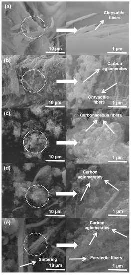
Figure 2. SEM images of (a) pure chrysotile, (b) Cris/Co600, (c) Cris/Co70700, (d) Cris/Co800, and (e) Cris/Co900 [3]. Copyright © 2016 Elsevier Ltd. Reprinted with permission from Elsevier.
4. Bentonite—Montmorillonite, Zeolite
Bentonite is an absorbent aluminum phyllosilicate, which is generally an adulterated clay typically comprised of montmorillonite. Bakandritsos and colleagues employed natural bentonite having the commercial name Zenith-N from the island of Mylos, Greece, obtained from Silver and Barytine Co. [4]. The raw material was found to contain montmorillonite (85%), feldspars (5%), calcite (3%), quartz (2.5%), illite (2%), cristobalite (2%), and the leftover of amorphous matter (0.5%). For CNTs’ growth, they placed the materials in a horizontal fixed-bed flow reactor for carbon chemical vapor deposition at 700 °C, using acetylene (C2H2) diluted with Ar 15% v/v gas mixture. The grown carbon nanofibers were found to have a mean diameter of 50 nm.
Further, in 2008, Kadlečíková and colleagues used natural montmorillonite (MMT) separated from bentonite from Stará Kremnička, Jelšový Potok, near the quarry at Kremnica, Slovakia [5]. Another sample used was zeolite tuff from the Nižný Hrabovec locality having a particle size of about 10 mm as a 2 mm-thick polished plate. Tuff is a compact igneous rock composed of minerals such as cristobalite, clinoptilolite, feldspars, and quartz. They employed CH4 in a hot filament CVD reactor for the CNTs’ growth. Further, on the quality of the grown CNTs, they studied the effect of catalyst parameters and the Fe3+ cations amount on the surface of the aluminosilicate. The difference that was concluded was that in the event of the particle montmorillonite, they faced a severe problem in the separation of the catalyst from the CNTs phase, while in the case of monolithic zeolite materials, this problem was easy to solve. The optimum mineral catalyst (from the point of view of the amount of CNTs) contains both irons as Fe3+ cations in exchangeable positions and Fe from the solution used to prepare Fe-MMT. They suggested that the main catalytic activity may be attributed to Fe atoms outside the interlayer space of MMT in disparity with Zhang and colleagues’ [6] work, where they suggested that the catalytically active particles are Fe atoms in the interlayer space.
Rinaldi and colleagues used bentonite from Winston Company, Germany, sold as Katzenstreu, and cat sand as a support and catalyst source for CNTs’ growth, as represented in Figure 3 [7]. The bentonite was at first reduced by hydrogen (75%) in helium. They found that sample was enlarged almost three times when it underwent ethylene flux in the CVD process for 1 hour. MWCNTs with varying wall thicknesses having an outer diameter in the range from 6 to 40 nm were obtained. The complex quality of CNTs could have originated from the various elements’ presences, and it was mainly due to the availability of two Fe sources (siderite and armalcolite) in the system. Figure 3d exhibits the HRTEM of the obtained CNTs having a lattice space of 0.21 nm along with the inclusive presence of Fe3C. The yield obtained was about 28.7% and the low surface of 33.1 m2g−1 could be due to the loss in microporosity and mesoporosity loss during the reduction process of bentonite. This also led to the fact that the bentonite matrix was not able to rebuild the porous system. The obtained CNTs were found to be of a highly graphitic structural order in comparison to the CNFs obtained on natural lava and soil. Further, they tested the mechanical stability of the CNTs/bentonite composite employing the ultrasonic treatment. For this, the obtained sample was immersed into two different types of solutions (water and hexane) and ultrasonication treatment was carried out for 2 h with nitrogen. Later on, they observed that the composite expanded twice the original volume in water solution without any noticeable suspended matter, while in the case of hexane, the composite expanded and filled over the container, which could be due to the hexane affinity towards the hydrophobic surface of CNTs. The solution was found to be stable for up to one week without any particle presence. SEM and nitrogen physisorption measurements did not disclose any major change in the morphological summary and adsorption/desorption, respectively. These results indicate the good mechanical stability of CNTs/bentonites composites.
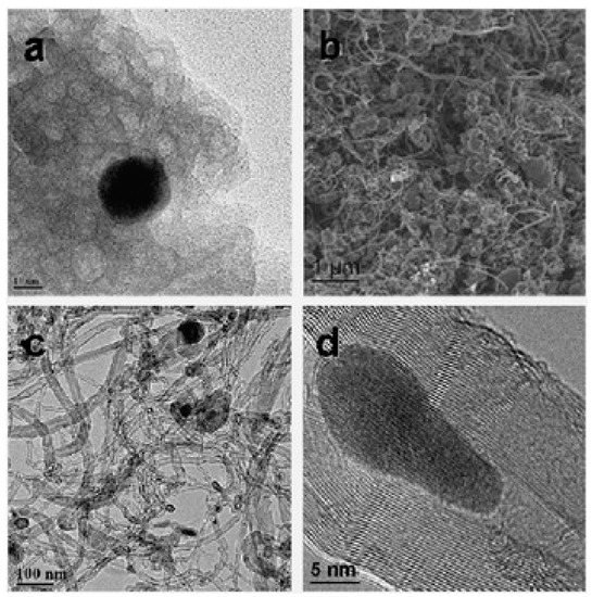
Figure 3. SEM and TEM images of bentonite: (a) reduced bentonite, (b) CNTs-bentonite composite, (c) CNT product, and (d) CNT-encapsulated Fe3C nanoparticle, [7]. Copyright © 2008 The Royal Society of Chemistry 2008. Reprinted with permission from The Royal Society of Chemistry.
In 2018, Huseynov and colleagues used natural bentonite ceramic clays from the Atyali and Gobu deposits of Azerbaijan for MWCNTs’ growth [8]. They employed the aerosol chemical vapor deposition technique with two types of carbon sources: cyclohexane—CyH (98%), and n-heptane—Hep (98%). SEM analysis displayed the high-purity and -quality growth of synthesized CNTs without any non-tubular form of carbon (soot, coke, etc.). MWCNTs were fashioned in an extended long filaments shape, having a diameter in the range of 48.2–123.9 nm and being 26.9 mm in length. Further, they employed the MWCNT/natural Azerbaijani bentonite for electro-conductive ceramic composites application.
5. Natural Laterite
Laterite is both a soil and rock type rich in Fe and Al contents and is considered to be formed via intensive and prolonged weathering of the underlying parent rock. Kumar and colleagues employed Ni laterite powder from Tiebaghi in New Caledonia for CNTs and CNSs syntheses via CVD using ethylene as a carbon source [9]. In the used laterite, the major micro-contents found were goethite, FeO(OH), and hematite (Fe2O3) along with a minor amount of phyllosilicates. It was observed that the pristine laterite powder was chemically bound with water, so it was first dehydrated via calcination and then reduced in the following sequence: FeO(OH) Fe2O3 > Fe3O4 > FeO > Fe, so that it could be effectively subjugated as a catalyst source. They observed that at 700 °C, mainly CNTs grew, while at 800 °C, CNSs started to form. They produced CNTs entangled in a “spaghetti-like” fashion, having a diameter in the range of 10–100 nm, while CNSs had a diameter of 500–700 nm. They clearly observed the existence of metal chunks inside some CNTs, along with amorphous carbon surrounding them, as depicted in Figure 4. Further, they proposed a plausible growth mechanism based on the fragmentation of the pristine iron-containing material, with probable reduction of Fe2O3 to metallic Fe particles to become the catalysts for CNT growth. They neglected the role of Ni for CNT growth, considering the Ni content to be of a low amount. In the case of CNS growth, they speculated that initially some nanometer-sized catalyst chunks are coated with amorphous carbon, which in turn prevents the growth of CNTs. Thus, these catalyst chunks, which are now unable to catalyze CNTs, further get coated by amorphous carbon during the remaining growth time.
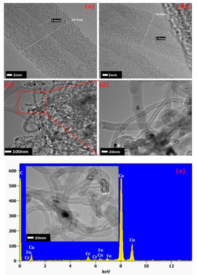
Figure 4. (a–d) HRTEM images of the CVD-synthesized CNTs at 700 °C and (e) their EDS analysis [9]. Copyright © 2018 American Chemical Society. Reprinted with permission from American Chemical Society.
6. Siliceous Breccia
Siliceous breccia is a natural rock mainly composed of α-quartz (SiO2) along with some inclusions of hematite (α-Fe2O3) and goethite (FeO(OH)) [10][11]. Kumar and colleagues used drill core siliceous breccia extracted from a mine in New Caledonia [12], as a catalyst source for the CNT growth via CVD. The effect of the H2 addition in the C2H4 precursor flow was also studied. The weight percent of iron (Fe) measured via EDS was observed to be very low, 0.39 wt.%. Iron was observed with a sub-micrometric presence irregularly dispersed all over the silicate segments, which acts as a catalyst and makes this material a suitable candidate for CNT growth, see Figure 5. The obtained CNTs were arranged in bundle formations having a diameter in the range of 25–35 nm. Moreover, the diluted C2H4/H2 stream changes the ratio of carbon to H2 and affects the carbon nanostructures’ growth, which results in the growth of CNTs with enhanced length and diameter. CNTs were found all over the catalyst source surface, having some regions containing dense agglomerations of as-grown CNTs, while some areas over the catalyst source surface did not show any presence of CNTs. This inhomogeneous growth may be because of the non-uniform distribution of iron oxide-hydroxide (α-Fe2O3, FeO(OH)) particles on the siliceous breccia surface.
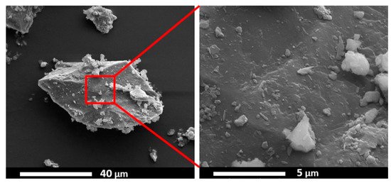
Figure 5. ESEM image of the siliceous breccia powder [12]. Copyright © 2019 Elsevier B.V. Reprinted with permission from Elsevier.
7. Vermiculite
Vermiculite clays are weathered mica having K+ in between the molecular sheets and are exchanged by Mg2+ and Fe2+ cations during weathering. Zhang and colleagues used vermiculite as a carrier of a catalyst mined from Lingshou, Hebei Province of China [13]. The vermiculite was composed of the following elements: SiO2 (42%), Al2O3 (12%), MgO (28%), Fe2O3 (13%), K2O (4.0%), CaO (0.5%), and H2O (0.5%), having a particle size of 10–100 µm. Vertically aligned CNTs in large amounts were grown in a fluidized bed reactor using ethylene as a carbon precursor. CNT arrays having a relatively uniform length, an inner diameter in the range of 3–6 nm—while an outer diameter of 7–12 nm—and up to several tens of microns in length were obtained, as shown in Figure 6. The as-grown CNTs possessed good alignment and exhibited a purity of ca. 84%. The results also support the use of a fluidic bed in comparison to a fixed-bed reactor, as the reactor provides a large, effective surface area and plenty of space for CNT growth [14]. Good heat and mass flow ensure the uniform temperature and reactant concentration in the entire fluidized bed, which is one of the key parameters for the controlled growth of CNT arrays.
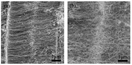
Figure 6. SEM images of junctions during CNT array growth time: (a) 15 min and (b) 60 min [13]. Copyright © 2009 Elsevier Ltd. Reprinted with permission from Elsevier.
8. Natural Lava
Mount Etna lava, a natural material, was employed as a catalyst and support for the synthesis of carbon nanomaterials [15]. Natural lava was first crushed in a powder and later the crushed powder was put into a horizontal quartz reactor and reduced with H2 before CVD treatment. For the CVD growth at 700 °C, ethylene was employed as a carbon precursor. A mixture of CNTs and CNFs was obtained on the lava rock. The SEM revealed that the obtained carbon nanomaterials were leading in CNF agglomerates. TEM measurements on the obtained CNFs and CNTs showed that they have a graphitic wall structure instead of a normal nanotube or nanofiber. The obtained CNTs and CNFs had a diameter on the scale of nanometers to micrometers. In later works, they were able to synthesize the CNTs/CNFs having excellent thermal stability up to 550 °C in a static air environment [16]. They had been competent enough to reveal that by choosing suitable experimental conditions, the morphology and structure quality of the carbon nanomaterials could be controlled and enhanced. Further, they stated, on the effect of the hydrocarbon flux flow, that upon high flux, the morphology of the carbon nanomaterial is disordered and more graphitic-like structures are obtained, while a lower hydrocarbon flux leads to ordered and well-defined growth of CNTs. Similarly, when the H2 flux flow was decreased, a significant change in the morphology and order of the carbon nanomaterials (CNFs to MWCNTs) was noticed. Next, upon decreasing the temperature, no significant alteration in the morphology of the carbon nanomaterials was observed.
9. Blended Iron Formation (BIF)
BIF primarily consists of hematite and magnetite grains alternating to quartz grain bands from thin bands of sedimentary rocks [17]. Luis and colleagues used BIF powder obtained from the Bundelkhand Craton, Northern India, as a catalyst source for the production of N-MWCNTs via aerosol-assisted catalytic chemical vapor deposition (AACCVD) [18]. The growth process is represented in Figure 7. Yield production as high as 340% wt./wt. was obtained by 1-hour ball-milled BIF powders, and this indicated that BIF powders can be employed for large-scale CNTs production. The produced CNTs had a diameter in the range of 20–200 nm. N-MWCNTs having diameter of 200 nm were found to have wrinkled or corrugated surfaces. Helical structures with diverse surface morphologies and diameters could be obtained, which could be due to the unevenly shaped catalytic particles. They discussed a possible scenario to explain N-MWCNT morphologies for the high CNT yield. Upon reduction, the Fe2O3 structure embedded inside the BIF nanoparticles is transformed into the α-Fe phase. In their system, small nanoparticles of the catalyst were found to have strong interaction with the SiO2 substrate, which remain fixed at their respective positions, and this hindered their catalytic performance. Further, this affects the growth of carbon nanomaterials, resulting in the complex NMWCNTs morphology. However, they predicted that the fixed nanoparticles in the system could lead to the thinner MWCNTs with individual longitudinal clumps, separated by the different size of the fixed catalytic nanoparticle. The thick NMWCNTs’ growth could be catalyzed by the combination of Fe3C and fixed catalytic nanoparticles inside the system. Due to the complexity of the catalytic materials, they tried to explain this phenomenon with several possible conditions (see Figure 8). However, they pointed out that these circumstances must be more thoroughly studied to understand this phenomenon. Further, they proposed the following hypothetical explanation for the high CNT yield obtained. They speculated that, first, the nitrogen coming from benzylamine decomposes at 950 °C and converts into benzyl and amino. They synthesized their samples at 850 °C and it is quite probable that at this temperature, benzylamine is not completely decomposed, resulting in only the interaction of benzyl with the nanocatalyst, leaving a fraction of amino. Minor Fe nanoparticles formed when the BIF sample underwent a reduction for 30 min. The superficial O2 bond at the SiO2 nanomaterial was weakened, and the O2 avoided the negative effect of H2 from benzyl, supporting the CNTs’ growth. They conceptualized that the CNTs yield could be enhanced by controlling the hydrogen activity with the oxygen from the SiO2 nanoparticle. In the scenario of N2, MWCNTs yield is decreased due to toluene. The obtained results exhibit that benzylamine increases the CeN which improves the yield of NMWCNTs. Next, they extended their activities to study the electrochemical response of NMWCNTs-composed electrodes in order to examine the obtained nanomaterial for energy storage and sensing applications.
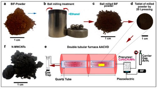
Figure 7. Schematic representation of the steps followed to obtain nitrogen-doped multi-walled carbon nanotubes (N-MWCNTs) using the banded iron formation (BIF) material as a catalyst. (a) Initial BIF powder with red-brown color, (b) Ball milling of 5 g BIF powder with 10 mL of ethanol was performed for 1 h, 2 h, and 3 h, (c) the obtained ball-milled BIF powders with dark brown color, (d) the tablet of the milled BIF powder by 20 t pressing, (e) AACCVD reactor wherein the tablets were positioned for growth, and (f) the as-obtained N-MWCNTs after growth [18]. Copyright © 2020 Elsevier B.V. Reprinted with permission from Elsevier.
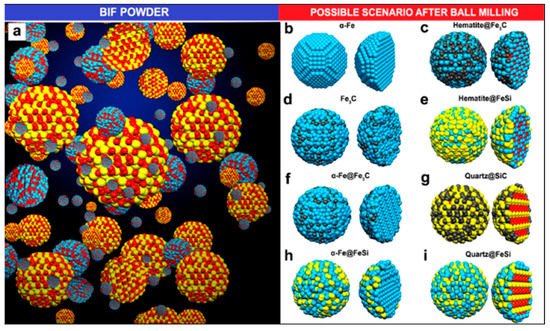
Figure 8. Schematic of the proposed scenarios for N-MWCNTs’ growth. (a) BIF powder grain’s ball-and-stick model and (b–i) possible circumstances after ball-milling process. Blue, red, yellow and black colours represents Fe, O, Si, and C ball-and-stick atoms, respectively. The BIF powder was mainly composed of hematite (Fe2O3) and quartz (SiO2) particles [18]. Copyright © 2020 Elsevier B.V. Reprinted with permission from Elsevier.
10. Wollastonite
Wollastonite is a type of calcium inosilicate (CaSiO3) material and is generally available from commercial mines in the PR of China, the USA, India, Finland, former Yugoslavia, Mexico, Greece, and other countries. Wollastonite shows many useful properties, such as low content of volatiles, high brightness, and whiteness, as well as low absorption of moisture and oil. These characteristics of the wollastonite material pave the way for extensive applications such as ceramic composites, paper, paint, vinyl tile manufacture, and plastics. Zhao and colleagues used wollastonite mined from Jiangxi, PR of China, exhibiting a fibrous structure in the form of needle-shaped crystals, as a natural substrate for the facile synthesis of aligned CNTs [19]. They showed that aligned CNTs could be easily obtained on wollastonite fibrous natural material via CVD. The obtained CNTs revealed good alignment and outer diameters ranging from 4 to 30 nm—while the distribution of the inner diameters ranged from 4 to 12 nm—and length distributions up to 15 µm. Raman spectroscopy evaluations gave values of ID/IG = 0.54 (D and G band intensity ratio in the Raman spectrum) for the CNTs, revealing the high degree of crystallization of the CNTs. Thermogravimetric analysis (TGA) in air showed that about 30 wt% of the wollastonite/CNT hybrid corresponded to CNTs with a sharp and narrow derivative thermogravimetric (DTG) peak with a high ignition temperature (676.1 °C), indicating the high quality of CNTs, see Figure 9. Further, the as-grown CNT arrays were easily purified to ca. 98.7%, providing a scalable route towards high-value, advanced materials with extraordinary performance.
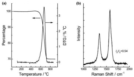
Figure 9. (a) TGA and DTG curves, and (b) Raman spectrum of the wollastonite/CNT hybrids yield [19]. Copyright © 2010 WILEY-VCH Verlag GmbH & Co. KGaA, Weinheim. Reprinted with permission from John Wiley & Sons.
11. Kaolinite, Nontronite, and Sepiolite
Sepiolite is a naturally occurring soft clay, with microcrystalline-hydrated magnesium silicate of the chemical formula Mg4Si6O15(OH)2·6H2O. Sepiolite has a low specific gravity, microfibrous morphology, and high porosity. Nie and colleagues employed sepiolite as a catalyst source mined from Nanyang, Henan Province of China [20]. They used sepiolite as the catalyst without any pre-treatment in a fixed-bed reactor with CH4 as a hydrocarbon source. After growth, small bundles of SWCNTs entangled with each other with a length of several hundred microns. SEM images showed a single graphene layer with minute defects. Further, they showed that more than 90% of the obtained products were SWCNTs. The size of the Fe catalyst cluster observed was about 20 nm. The diameters of the obtained SWCNTs ranged from 1 to 40 nm depending upon temperature and the amount of metal loading. The chirality and diameter distribution were highly dependent on the reaction temperature. Raman spectroscopy was employed to analyze the graphitization degree and the diameter distribution of the obtained SWCNTs. Raman intensity ratios of the D to G bands were 0.07, 0.14, and 0.08 under the excitation wavelength of 633, 514, and 532 nm, respectively (Figure 10a–c). This indicates the high degree of graphitization for the as-grown SWCNTs. On the other hand, sharp RBM peaks were also observed in different Raman spectra. The diameter distribution of obtained SWCNTs products was estimated by the following equation: x = 248/d [21]. The strong peaks appeared on the RBM patterns at all the excitation wavelengths, namely, 633, 514, and 532 nm, with the corresponding diameters in the ranges of 1.0–1.9, 1.3–1.8, and 0.8–1.9 nm, respectively. The CNT obtained via this method was further employed for phenol absorption.
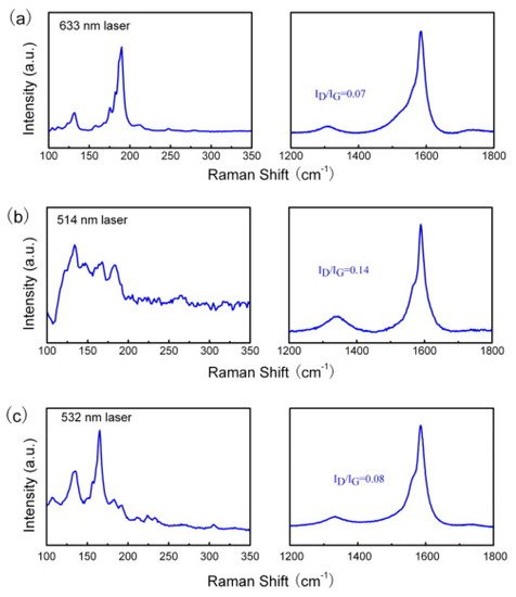
Figure 10. Raman spectra of the single-walled carbon nanotube (SWCNT) at the different excitation wavelengths: (a) 633, (b) 514, and (c) 532 nm [20]. Copyright © 2010 Elsevier Ltd. Reprinted with permission from Elsevier.
Additionally, kaolinite, nontronite, and sepiolite are the types of microcrystalline phyllosilicates. Astorková and colleagues used kaolinite (commercial name kGa-2), clay from Warren County, Georgia, USA, nontronite (NAu-2), natural dark-brown clay from Uley Mine, South Australia, and sepiolite (SepSp-1) from Valdemore, Spain, as catalyst sources for CNTs synthesis via hot filament chemical vapor deposition (HFCVD) [22]. As nontronite belongs to clay minerals with a high Fe content, this material was not modified, while kaolinite and sepiolite were doped with catalytically active metal particles. The diameter distribution of MWCNTs grown on nontronite ranges from 10 to 50 nm with different shapes, see Figure 11a. For example, chain-like nanotubes are made of hollow carbon cages that are interconnected so that the open end of one cage is joined with the dome of another one. In Figure 11b, we can see the bamboo-shaped CNTs. EDS on CNT/nontronite identifies the presence of iron but also Al and Ca, indicating that the Fe particles help in the growth of CNTs. Further, it was found that, in the case of kaolinite, the nanotubes are located between single crystallites; they grow through the whole volume and create 3D grids. In the cases of nontronite and sepiolite, the CNTs grow through the volume of the mineral while creating an additional identifiable discrete phase. While it was observed that CNTs are non-aligned on nontronite, they are aligned in the case of sepiolite.
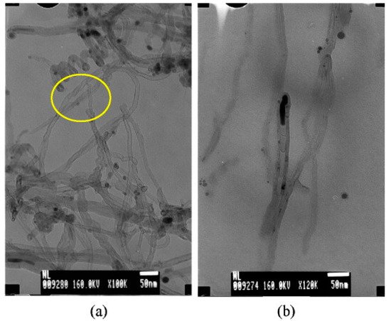
Figure 11. (a) TEM image of the carbon grown on nontronite. (b) TEM micrograph of a bamboo-like structure of CNTs [22]. Copyright © 2011 Elsevier B.V. Reprinted with permission Elsevier.
This entry is adapted from the peer-reviewed paper 10.3390/physchem1010002
References
- Endo, M.; Takeuchi, K.; Kim, Y.A.; Park, K.C.; Ichiki, T.; Hayashi, T.; Fukuyo, T.; Iinou, S.; Su, D.S.; Terrones, M.; et al. Simple synthesis of multiwalled carbon nanotubes from natural resources. ChemSusChem 2008, 1, 820–822.
- Kawasaki, S.; Shinoda, M.; Shimada, T.; Okino, F.; Touhara, H. Single-walled carbon nanotubes grown on natural minerals. Carbon 2006, 44, 2139–2141.
- Lemos, B.R.S.; Soares, A.R.; Teixeira, A.P.C.; Ardisson, J.D.; Fernandez-Outon, L.E.; Amorim, C.C.; Lago, R.M.; Moura, F.C.C. Growth of carbon structures on chrysotile surface for organic contaminants removal from wastewater. Chemosphere 2016, 159, 602–609.
- Bakandritsos, A.; Simopoulos, A.; Petridis, D. Iron changes in natural and Fe(III) loaded montmorillonite during carbon nanotube growth. Nanotechnology 2006, 17, 1112–1117.
- Kadlečíková, M.; Breza, J.; Jesenák, K.; Pastorková, K.; Luptáková, V.; Kolmačka, M.; Vojačková, A.; Michalka, M.; Vávra, I.; Križanová, Z. The growth of carbon nanotubes on montmorillonite and zeolite (clinoptilolite). Appl. Surf. Sci. 2008, 254, 5073–5079.
- Zhang, W.D.; Phang, I.Y.; Liu, T. Growth of carbon nanotubes on clay: Unique nanostructured filler for high-performance polymer nanocomposites. Adv. Mater. 2006, 18, 73–77.
- Rinaldi, A.; Zhang, J.; Mizera, J.; Girgsdies, F.; Wang, N.; Hamid, S.B.A.; Schlögl, R.; Su, D.S. Facile synthesis of carbon nanotube/natural bentonite composites as a stable catalyst for styrene synthesis. Chem. Commun. 2008, 6528–6530.
- Huseynov, A.; Israfilov, A.; Mammadova, S.; Abdullayeva, S.; Sokolov, S.; Goryunkov, A.; Guliyev, A. Fabrication and characterization of MWCNT/natural Azerbaijani bentonite electroconductive ceramic composites. J. Compos. Mater. 2019, 53, 3909–3923.
- Kumar, A.; Kostikov, Y.; Orberger, B.; Nessim, G.D.; Mariotto, G. Natural Laterite as a Catalyst Source for the Growth of Carbon Nanotubes and Nanospheres. ACS Appl. Nano Mater. 2018, 1, 6046–6054.
- Secchi, M.; Zanatta, M.; Borovin, E.; Bortolotti, M.; Kumar, A.; Giarola, M.; Sanson, A.; Orberger, B.; Daldosso, N.; Gialanella, S.; et al. Mineralogical investigations using XRD, XRF, and Raman spectroscopy in a combined approach. J. Raman Spectrosc. 2018, 49, 1023–1030.
- Duée, C.; Maubec, N.; Laperche, V.; Capar, L.; Bourguignon, A.; Bourrat, X.; Mendili, Y.E.; Chateigner, D.; Gascoin, S.; Mariotto, G.; et al. Combined mineralogy and chemistry on drill cores: Challenging for on-line-real-time analyses. In Proceedings of the 14th Biennial SGA Meeting, Quebéc, QC, Canada, 20–23 August 2017; Volume 3, pp. 1241–1244.
- Kumar, A.; Kostikov, Y.; Zanatta, M.; Sorarù, G.D.; Orberger, B.; Nessim, G.D.; Mariotto, G. Carbon nanotubes synthesis using siliceous breccia as a catalyst source. Diam. Relat. Mater. 2019, 97, 107433.
- Zhang, Q.; Zhao, M.Q.; Huang, J.Q.; Liu, Y.; Wang, Y.; Qian, W.Z.; Wei, F. Vertically aligned carbon nanotube arrays grown on a lamellar catalyst by fluidized bed catalytic chemical vapor deposition. Carbon 2009, 47, 2600–2610.
- Wei, F.; Zhang, Q.; Qian, W.Z.; Yu, H.; Wang, Y.; Luo, G.H.; Xu, G.H.; Wang, D.Z. The mass production of carbon nanotubes using a nano-agglomerate fluidized bed reactor: A multiscale space-time analysis. Powder Technol. 2008, 183, 10–20.
- Dang, S.S.; Chen, X.W. Natural lavas as catalysts for efficient production of carbon nanotubes and nanofibers. Angew. Chemie Int. Ed. 2007, 46, 1823–1824.
- Su, D.S.; Rinaldi, A.; Frandsen, W.; Weinberg, G. Nanocarbons: Efficient synthesis using natural lava as supported catalyst. Phys. Status Solidi 2007, 244, 3916–3919.
- Katsuta, N.; Shimizu, I.; Helmstaedt, H.; Takano, M.; Kawakami, S.; Kumazawa, M. Major element distribution in Archean banded iron formation (BIF): Influence of metamorphic differentiation. J. Metamorph. Geol. 2012, 30, 457–472.
- Jimenez-Ramirez, L.E.; Kashina, S.; Galindo, R.; Fuentes-Ramirez, R.; Verma, S.K.; Fajardo-Diaz, J.L.; López-Urías, F.; Muñoz-Sandoval, E. Synthesis, morphology, magnetic and electrochemical studies of nitrogen-doped multiwall carbon nanotubes fabricated using banded iron-formation as catalyst. J. Alloy. Compd. 2020, 835, 155200.
- Zhao, M.Q.; Zhang, Q.; Huang, J.Q.; Nie, J.Q.; Wei, F. Advanced materials from natural materials: Synthesis of aligned carbon nanotubes on wollastonites. ChemSusChem 2010, 3, 453–459.
- Nie, J.Q.; Zhang, Q.; Zhao, M.Q.; Huang, J.Q.; Wen, Q.; Cui, Y.; Qian, W.Z.; Wei, F. Synthesis of high quality single-walled carbon nanotubes on natural sepiolite and their use for phenol absorption. Carbon 2011, 49, 1568–1580.
- Dresselhaus, M.S.; Dresselhaus, G.; Saito, R.; Jorio, A. Raman spectroscopy of carbon nanotubes. Phys. Rep. 2005, 409, 47–99.
- Pastorková, K.; Jesenák, K.; Kadlečíková, M.; Breza, J.; Kolmačka, M.; Čaplovičová, M.; Lazišťan, F.; Michalka, M. The growth of multi-walled carbon nanotubes on natural clay minerals (kaolinite, nontronite and sepiolite). Appl. Surf. Sci. 2012, 258, 2661–2666.