The incorporation of phase change materials (PCM) in buildings has the potential to enhance the thermal efficiency of buildings, reduce energy cost, shift peak load, and eventually reduce air pollution and mitigate global warming. However, the initial capital cost of PCM is still high, and thus the establishment of a control strategy has become essential to optimize its use in buildings in an effort to lower investment costs.
- phase change material
- ON/OFF control
- conventional control
- intelligent control
- buildings
1. Introduction
In recent years, population growth and industrial developments have resulted in a dramatic increase in energy consumption and greenhouse gas emissions. Figure 1 and Figure 2 show the rising trend of total energy consumption [1,2] and CO2 emissions [3], over the period between 1990 and 2019, respectively. According to the statistics of the U.S. Energy Information Administration, today’s rate of energy consumption is higher than its production, which is a cause of significant concern about the future availability of energy [4]. Studies confirm that the building sector is one of the most prominent energy consumers, worldwide. Almost 50% of energy is consumed in buildings in the USA [5], 40% in Europe, and 36% worldwide, of which space heating and cooling account for approximately 50% [6]. Thus, energy demand with an annual rate of increase of 2.3% has created awareness towards the need to use renewable sources of energy to reduce climate change and achieve sustainable development [7].
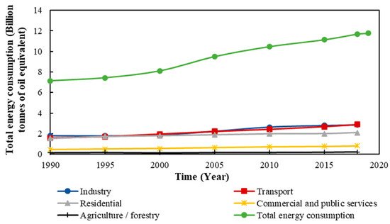
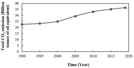
Figure 2. World’s total CO2 emissions from 1990 to 2019 [3].
Significant attention has been directed to manage the growing energy demand, energy security, and energy consumption pattern, especially by heating, ventilation and air conditioning (HVAC) systems, and their associated grid loads [8]. In many parts of the world, for example, direct solar radiation is a promising source of energy as it is free, renewable, unlimited, and eco-friendly. In solar heating applications, a building can either absorb solar energy passively without requiring any mechanical and electrical devices [9] or use of auxiliary equipment to efficiently convert solar energy to thermal or electrical energy [10]. Solar energy varies according to the time of the day, season, climatic conditions, and other factors. Generally, solar radiation flux reaches its maximum level at midday, while it diminishing to zero at sunset. To tackle this limitation, thermal energy storage (TES) systems allow excess heat or cooling energy to be stored for later use. TES or enhanced thermal mass is that property of materials that defines their ability to absorb, store and release heat according to the surrounding conditions. TES increases the overall efficiency and reliability of heating and cooling by providing thermal comfort and indoor temperature stabilization. Additionally, it reduces the pollution, and CO2 emission associated with fossil fuel use [11].
Thermal energy is stored in materials through sensible heat by changing the temperature of material [12], latent heat by altering the phase of material within a narrow temperature range [13], and through reversible thermochemical reactions [14]. Among different TES systems, latent heat thermal energy storage has attracted wide attention due to its ability to store a large amount of energy per unit volume, isothermally, by using phase change materials (PCMs). Studies show that PCMs can store heat per unit volume 5–14 times more than sensible heat storage materials [15]. Figure 3 compares the thickness of building construction materials required to store the same amount of energy (the energy required to increase the temperature of 240 mm concrete from 20 °C to 30 °C). Thermochemical energy storage materials are also technically complex and challenging to apply, and hence require higher capital expenditure [16].
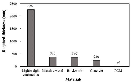
Figure 3. The thickness of building materials required to store the same amount of energy [17].
PCMs are divided into organic materials, such as paraffin and non-paraffin-based compounds, inorganic materials, such as hydrated salts and metallics, and eutectics [18], which are a mixture of components with a freezing point less than the individual components. Figure 4 illustrates the classification of the PCMs [19]. All PCM types have some advantages and disadvantages [20] which are summarized in Table 1.
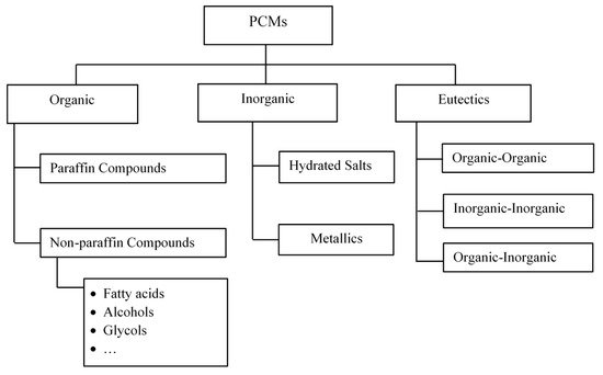
Figure 4. Classification of phase change materials (PCMs) [19].
Table 1. Advantages and disadvantages of different type of PCM [20].
| PCMs | Advantages | Disadvantages |
|---|---|---|
| Organic |
|
|
| Inorganic |
|
|
| Eutectics |
|
|
An ideal phase change heat storage material should exhibit some desirable thermodynamic, chemical, kinetic, and economic properties. Following are some of the criteria used to select the proper PCM [13,18,21].
Thermodynamic properties:
- -
-
A melting point within the temperature range of application;
- -
-
High latent heat of fusion per unit mass and volume, so that a smaller amount of material is required to achieve a certain energy storage capacity;
- -
-
High specific heat capacity to take advantage of significant sensible heat storage effect;
- -
-
High thermal conductivity, so that heat could be absorbed or released faster;
- -
-
Small volume changes during the phase transition;
- -
-
Congruent melting;
- -
-
Small vapor pressure.
Chemical properties:
- -
-
Experiencing reversible freezing/melting cycle;
- -
-
Chemical stability which means being non-corrosive and not being decomposed during the freezing/melting cycle;
- -
-
Non-toxic and non-flammable.
Kinetic properties:
- -
-
High nucleation rate to avoid supercooling;
- -
-
High rate of crystal growth to meet demands of heat recovery from the storage system.
Economic properties:
-
-
-
Cost-effective;
-
-
-
Available in large quantities.
2. Different Control Strategies Applied to PCM-Enhanced Buildings
Different control strategies have been applied to PCM-enhanced buildings to control the operation of the mechanical and electrical devices and hence ensure indoor comfort and minimize electricity consumption, cost associated with energy consumption, and CO2 emissions. Control strategies can be divided into different categories such as ON/OFF control, classical control (P, I, PI, PID, etc.), adaptive, optimal and predictive control, and intelligent controls [68], which are discussed thoroughly in the following subsections.
2.1. ON/OFF Control
ON/OFF control, also known as hysteresis control, is the simplest feedback control method that switches the manipulated variable between two states of ON or OFF, abruptly. ON/OFF controller uses the upper and lower bound of the objective variable to regulate the process within the given thresholds [70]. As an example, Gholamibozanjani and Farid [71] implemented an ON/OFF control strategy in an experimental hut equipped with PCM storage to ensure its thermal comfort in different seasons of the year. In winter, for instance, the PCM storage system was ON if the PCM temperature was higher than the indoor room temperature; otherwise, an electric heater was automatically started to maintain the comfort condition. Such controllers can drive the manipulated variables from a fully open to a fully closed state and vice versa over a specified period. Solgi et al. [72] implemented a night ventilation technique to lower the summer cooling demand of an office building in hot-arid areas. The night ventilation was scheduled to automatically start once the outdoor temperature dropped below 30 °C and to stop at 7 a.m., thus solidifying the PCM using the coolness available at night and then melting it to absorb heat during the day.
Although the ON/OFF control method is inexpensive, simple and easy to implement, it is not able to control dynamic processes with time delays [73] as it is either fully ON or fully OFF, and hence causes chattering in the control output. In fact, a proper hysteresis is required, which otherwise would make output deviate from the temperature set-point. Moreover, considerable signal noise is introduced to the measuring process, which results in inaccurate output measurements [74].
Kenisarin and Mahkamov [75] performed a review on controlling thermal comfort in small laboratory models and real-size test rooms enhanced with a PCM applied passively. Implementation of such control strategies aims to meet different primary objectives such as energy-saving, electricity cost-saving and peak load shifting while maintaining indoor thermal comfort; these are discussed in depth in the following subsections.
2.1.1. Overall Energy Consumption Reduction
Application of control strategies to a building can enhance its energy efficiencies and hence reduce the pollution associated with fossil fuel consumption used for power generation [76]. Chen et al. [77] examined the effect of combined night ventilation and thermal energy storage using PCM to reduce the energy consumed for space cooling in an office building. In their simulation-based study, a typical south-facing office room located in Beijing, China, was considered as a base case for their study; also, a control algorithm was implemented to regulate the indoor temperature. Based on the control algorithm, during the period from 8 a.m. to 6 p.m. (office hours), fresh air was always provided for the occupants. However, if room temperature exceeded the higher bound of comfort level by 1 °C, the PCM started cooling down the room. If room temperature exceeded the comfort level by 2 °C, and the 3-min shut-off period of the air conditioner was met, the air conditioner would hence start. During the night (from 6 p.m. to 8 a.m.), outdoor air was introduced to the storage unit to solidify the PCM to be used during the following day. The results showed that it was possible to achieve energy saving between 16.9% and 50.8%. Another example of night ventilation, based on the ON/OFF control algorithm showed reduced electrical energy consumption and as a consequence reduced CO2 emission [78].
In addition, by using a simulation tool, Transient Systems (TRNSYS), Wang et al. [79] proved that the implementation of a control strategy into a ground heat pump system in conjunction with PCM reduced electrical energy consumption in Xi’an (Humid Subtropical Climate in China). They showed 7.9 °C improvements in the average temperature of the heat pump with an increase in its average coefficient of performance (COP) from 3.4 to 3.8.
Table 2 summarizes the studies carried out on the application of ON/OFF controller in combination with PCM for the sake of reducing energy consumption and indoor temperature fluctuation. In this table, type of PCM used and its integration place, the reason for using a controller, scale of the study, type of study (experimental/numerical) and energy benefits were reported.
Table 2. Application of ON/OFF controller in PCM-enhanced buildings for energy consumption reduction.
PCM Type Controller Performance Spatial Scale PCM Integration Place Type of Study Energy Benefits Ref. PCM with a melting temperature of 29 °C Indoor temperature was controlled by a thermostat set at 20 °C Not mentioned Into a solar thermal collector Experimental Reduction in natural gas consumption by about 50% in Alberta, Canada. [80] PCM with a melting temperature of 25 °C Activating external shading as well as night ventilation Not mentioned Interior walls Numerical & experimental 30% less indoor temperature fluctuation over seven days in Freiburg, Germany. [81] Mixture of capric acid and lauric acid Operating an electric heat membrane placed in the ceiling 5.0 × 3.3 × 2.8 m3 PCM-impregnated gypsum boards were installed on the walls. Experimental Application of PCM reduced the maximum thermal flow by 14%, over three days in Shenyang, China and created peak load shifting [82] A paraffin-based PCM with a melting temperature of 27 °C Indoor room temperature was controlled by connecting a thermostat to a chilled water system 1.83 × 1.83 × 1.52 m3 PCM was encapsulated in copper pipes and were placed horizontally in the stud walls. Experimental - Overall cooling load was reduced by 9 to 11% when 10 and 20 wt.% PCM was used, in Kansas, USA.
- Peak heat load reduced by 37% and 62%, when 10 and 20 wt.% PCM was used.[83,84,85] A bio-based PCM with a melting point of 29 °C A thermostat was connected to a heat pump 4.9 × 3.7 × 2.4 m3 PCM was encapsulated into a small blocks in a mat sheet to be installed in the walls, ceiling and floor, a layer between insulation and gypsum board. Experimental Energy savings of 12 to 26% in summer, and 9 to 29% in winter were achieved, based on the Arizona State, USA weather conditions. [86] Micronal DS-5008X 8 h of absorbing heat from outside followed by 16 h of releasing heat to inside 0.1 × 0.1 × 0.1 m3 PCM-gypsum composite heat storage in ceiling for ventilation Numerical & experimental Less indoor temperature variation was achieved for the weather condition of Poland. [87] CaCl2·6H2O A controller was used to determine between three modes in summer:
1- Natural ventilation to absorb daytime excess heat.
2- Natural cooling energy storage at night
3- Natural cooling energy storage release at night.5.0 × 4.0 × 3.0 m3 PCM was integrated into a Trombe wall and a PV/T panel Numerical & experimental - An annual net electricity efficiency of 13% was achieved based on weather condition of Changsha, China.
- Photovoltaic efficiency increased from 11.5% to 15%.[88,89] A PCM with a latent heat of 219 kJ/kg and melting temperatures from 21 °C to 31 °C HVAC system was operating from 12 to 8 a.m. and 4 p.m. to 12 a.m. if PCM cannot provide comfort. A two-story building, each store was 9.2 × 12.2 × 2.6 m3 Different locations in walls: interior, middle and exterior Numerical Up to 67% energy saving was achieved in a tropical climate. [90] CaCl2 · 6H2O Tank temperature was controlled by the heat pump operation to provide indoor comfort condition. Thermal capacity of building was 13.32 MJ/K. Integrated into the heat pump unit Numerical The performance of solar assisted ground-source heat pump improved by 12.3%. [91] Micronal® PCM microcapsules Cooling started when indoor temperature exceeded 25 °C and heating mode was ON when it dropped below 18 °C 2.4 × 2.4 × 2.4 m3 Interior surface of exterior walls and roof Numerical Use of PCM maintained comfort condition 10 to 30% more than a case with no PCM, depending on weather conditions [92] 2.1.2. Cost Saving
Integration of PCMs into buildings can serve to make energy-savings by storing solar energy for later use (heating) or by storing free cooling available at night in summer (cooling). Changing the electricity consumption pattern by end-use customers, on the other hand, plays a significant role in managing demand resources and cost-saving. In this regard, postponing the use of electricity during high wholesale market price periods and using it during cheaper hours is an effective approach to demand responses [69]. For example, in 2015, Barzin et al. [93] initiated a “price-based” control strategy in a PCM-enhanced building for space heating. They examined the potential of PCM technology in conjunction with underfloor heating in an office-size building at the “University of Auckland,” New Zealand. Figure 5 shows a general view of the data acquisition and control system applied to their experimental building. According to their control system, the underfloor heater was switched ON or OFF based on the online dynamic electricity price, price constraint, and desired room temperature, which algorithm is shown in Figure 6. The experimental measurements over five days in winter confirmed a total energy-saving of about 18.8% with a corresponding 28.7% of cost-saving, while the highest energy and cost-saving were equal to 35% and 44.4%, respectively.
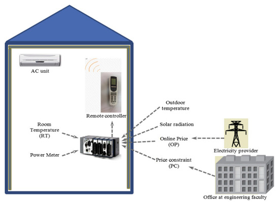
Figure 5. Control system used in Barzin et al. study [93].
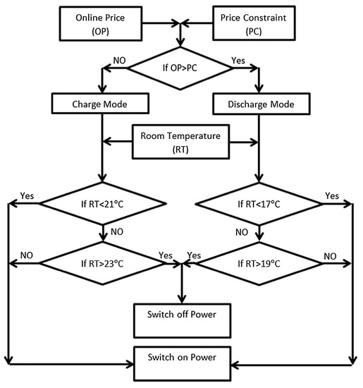
Figure 6. The control strategy applied to the huts of the University of Auckland for passive space heating [93].
Barzin et al. [6] also implemented a price-based control strategy for space cooling in summer, based on the weather conditions in Auckland which has a “Marine West Coast Climate”. Two similar experimental huts (interior dimensions 2.4 m × 2.4 m × 2.4 m), each constructed with light-weight materials and provided with 1 m × 1 m north-facing windows, were used to perform some experiments. One of the huts, referred to as “hut 1”, was considered a reference for experiments, and its walls and ceilings were finished with 13 mm gypsum boards. While the other hut, referred to as “hut 2” was finished with PCM-enhanced gypsum boards. The PCM used was PT20 with a narrow melting temperature of about 20 °C. Both huts were also equipped with air conditioning units. The aim of the “price-based” control strategy was to keep the indoor room temperature in summer between 17 °C and 19 °C during off-peak periods (when the online price was lower than price constraint), and between 24 °C and 26 °C, during on-peak hours (when the online price was higher than the price constraint). An air conditioner was used to provide the comfort condition, but 100% more energy was consumed in hut 2 compared to hut 1, over 6 days. Therefore, they tried applying night ventilation in combination with air conditioning during the daytime, showing an energy-saving of about 73% over one week.
2.1.3. Peak Load Shifting
Peak demand or peak load is referred to as the maximum demand over a specific billing period. Peak demand usually varies for different types of buildings. Usually, residential users are charged based on a single tariff rate and only recently some electricity suppliers provided a variable electricity rate for the sake of peak load shifting. The incentive of peak load shifting for residential users would be electricity cost saving as well as improved quality and reliability of power. Peak demand for a commercial building lasts for a short period; however, it counts for half of the overall electricity bill. Hence, peak load shifting can not only reduce the peak demand, but it also saves substantially on energy costs [94]. Studies show that peak load management can lead to $10–$15 billion cost-saving in the US market annually [95]. Figure 7 illustrates the schematic view of a typical peak load shifting in summer.
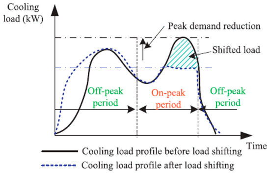
Figure 7. Overall view of a typical peak load shifting [94].
There are other benefits from offsetting the peak load including the reduction of generation of electricity from non-renewable energy sources during periods of peak demand and resilience during times of power outages. Even if a renewable source of energy is used, its generation during peak demand is not guaranteed as it may be cloudy, for instance, when solar energy is used. Power generation companies usually design their systems based on average load. Thus, any peak demand requires auxiliary equipment which causes extra cost, maintenance, and pollution that can be prevented by peak load shifting. On the other hand, as power generation facilities age, equipment failures accelerate, and as the demand for power increases over the years, existing plants have trouble meeting load requirements. To compensate for this, a plant may elect to install an energy storage system that can be charged when demand is low and discharged when demands cannot be met by the primary generation source.
Shifting of peak load also reduces losses in the transmission and distribution systems and hence carbon emission will be reduced as a result of more efficient operation of power plants and less load variability.
Studies show a significant potential of PCMs in peak load shifting [96]. In most cases, there is either no control strategy or only an ON/OFF control strategy. However, the best results have been achieved with control strategies. Peak load shifting control applied to PCM-enhanced buildings can be divided into two groups based on PCM integration into either the building envelope or into HVAC systems.
In terms of PCM incorporation into the building envelope, Khudhair and Farid [97], proved the concept of peak load shifting by charging the PCM-enhanced gypsum boards using electrical energy during low-demand hours to be used during high-demand hours. In Canada, Bastani et al. [98] also evaluated the effect of an ON/OFF control on shifting heating peak demand of a real bungalow building integrated with PCM wallboards. Through a numerical study via TRANSYS, they considered five different room set-point temperature ranges such as 20 °C–25 °C, 19 °C–24 °C, 18 °C–23 °C, 20 °C–24 °C, and 20 °C–23 °C. The PCM melting and solidification temperatures were 23 °C and 17 °C, respectively. Based on their control strategy, during the off-peak hours from midnight until 5:30 a.m., a heater was set in operation to charge the PCM and hence maintained the room temperature at the upper bound of comfort level. Then, during peak hours from 5:30 a.m. to 9:30 a.m. the heater was OFF, but PCM kept the room temperature at the lower bound of comfort level. Results showed that larger indoor temperature swings resulted in a higher total daily energy consumption and a lower peak load shifting. Moreover, setting the operational temperature range closer to the melting and solidification temperatures of PCM, 18 °C–23 °C, for instance, resulted in better utilization of the PCM and a longer period of peak load shifting. Barzin et al. [99] conducted another price-based control strategy for peak load shifting in winter. In their study, two experimental huts were finished with 13 mm gypsum boards and equipped with identical electric heaters. However, one of the huts was internally lined with DuPont PCM wallboards having a melting temperature of 21.7 °C. The indoor air temperatures were planned to be kept between 21 °C and 23 °C during off-peak hours, and between 17 °C and 19 °C, during peak hours. The thermal performance of the hut was then compared. Table 3 summarizes the energy and cost-savings of the PCM-enhanced hut over six days, based on the weather conditions in Auckland.
Table 3. Power and cost-savings for six days of winter [99].
Days 1 2 3 4 5 6 Total Power saving (%) 0.24 32.03 −9.39 15.64 60.08 36.5 21.5 Cost-saving (%) 1.43 45.08 −6.81 16.02 62.64 44.00 26.7 Peak load shifting can also be achieved through the integration of PCMs into heat exchangers [100]. For instance, the potential of an air-PCM heat exchanger unit for peak load shifting was investigated by Stathopoulos et al. [101] in France. In their experimental work, a heat exchanger unit composed of a set of plates containing paraffin having a melting point of 37 °C (Figure 8) was integrated into a ventilation system in a test cell, known as “Hybcell”. Considering thermal comfort and indoor air quality of Hybcell, the aim was to reduce peak demand, particularly during late afternoon periods in winter. To this end, a preliminary control strategy was introduced to evaluate the capability of the system for peak load shifting. An electrical resistance heater was also provided to charge PCM and warm up the test cell during off-peak hours, then the PCM was discharged during peak hours. The experimental measurements showed that the proposed design allowed peak load reduction while the Hybcell met the thermal comfort requirement of 21 °C. On the other hand, a numerical model was developed using the specific heat capacity method, developed by Farid [102], and coupled to a building simulation program. The model could accurately predict the experimental measurements. Figure 9 compares the calculated and experimental results of the heat exchanger unit and the test cell performance during a four-day test, where the grey highlighted parts correspond to the peak demand period (6 p.m. to 8 p.m.).
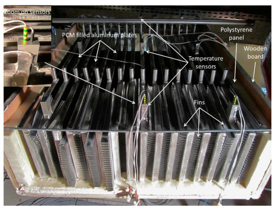
Figure 8. PCM storage unit used for peak load shifting in Stathopoulos et al. study [101].
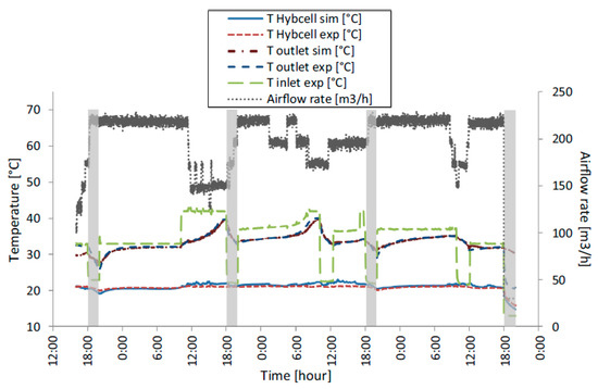
Figure 9. Numerical and experimental results for the PCM storage unit for peak load shifting over four days [101].
Using PCMs in underfloor heating is another method that can not only reduce electricity costs but also shift the heating load to off-peak hours. Devaux and Farid incorporated a PCM (melting range 27–29 °C) in an underfloor heating system in combination with another lower melting point PCM (21.7 °C) in the walls and ceiling of a 2.63 m × 2.64 m × 2.64 m hut. The results showed that the lower melting point PCM helped to maintain comfort condition, while the higher melting point PCM, in the underfloor heating system, created peak load shifting with energy and cost saving of 32% and 42%, respectively [103].
Table 4 shows the application of ON/OFF controller for peak load shifting in some other studies.
Table 4. Application of ON/OFF controller in PCM-enhanced buildings used for peak load shifting.
PCM Type Controller Performance Spatial Scale PCM Integration Place Type of Study Energy Benefits Ref. Paraffin-based PCM Electric heater was controlled by either time or temperature. It was ON from 23 p.m. to 7 a.m. if temperature was lower than 65 °C. 3.0 × 2.0 × 2.0 m3 On the floor in combination with underfloor heating Numerical & experimental The total heating energy demand, based on the weather conditions of Tsinghua (China), was shifted to off-peak hours [104] Not mentioned PCM was charged from 12 a.m. to 5:30 a.m. and discharged during peak hours, considering five comfort ranges such as 20–25 °C, 19–24 °C, 18–23 °C, 20–24 °C, and 20–23 °C.
A heater assisted automatically to maintain comfortFloor area: 12.8 × 8.1 m2 Building envelope Numerical Shifting energy consumption from 3 to 10 h based on weather condition and desired comfort range, in winter (in Quebec, Canada) [98] A PCM with a melting point of 40 °C Two control scenarios: -
Indoor thermostat, which ensured the indoor thermal comfort by adjusting heat flow from heater.
-
Storage thermostat which controls the inlet temperature of the baseboard heat exchanger before entering the room.
Total floor area: 136 m2
Total volume: 448 m3PCM was integrated into a heat pump Numerical - -
-
Peak load shifting of 2 to 6 h was created in a residential building based on the weather condition of Hamilton, Canada.
[105,106] A PCM with a melting point of 27 °C A controller was used to maintain indoor temperature at 21 °C 5.87 × 2.38 × 2.31 m3 PCM was integrated into a radiant floor. Numerical - -
-
A peak load shifting of 1.1 h/day was created.
- -
-
18% of electricity cost was saved.
[107] Paraffin RT20 A controller was used to switch on a heater during off-peak hours and switch it off during peak hours, while maintaining comfort level. 2.6 × 2.6 × 2.6 m3 PCM was incorporated into walls and ceiling. Experimental Energy saving and peak load shifting were achieved depending on the minimum and maximum outdoor temperature. [108] Mixture of capric acid and lauric acid A controller was connected to an HVAC system to provide comfort in summer. Floor area: 16 m2 PCM was integrated into air conditioning duct Experimental - -
-
PCM helped to maintain indoor room temperature rise less than 0.8 °C for 2.5 h during peak hours of summer in China.
- -
-
16% energy saving was achieved.
[109,110] Coconut oil A controller was used to switch on a heater when room temperature fell below comfort temperature. 1.18 × 1.18 × 1.21 m3 PCM was integrated into underfloor heating. Experimental Electricity consumption was shifted by 57% when PCM was used in a simulated cold weather with a temperature between 0 °C and 5 °C. [111] RT15 and RT8HC RT8HC and RT15 were cooled at 1 °C and 7 °C, respectively, for 7 h. RT8HC was charged using electricity and RT15 was charged using free night cooling. Both were discharged at 24 °C, for 10 h. A three-story building each with dimensions of 32.0 × 16.0 × 3.5 m3 PCM storage unit (an air-PCM heat exchanger unit) Numerical A yearly cooling peak load shifting of 15% was reported using London Gatwick design weather data. [112] Mixture of Capric acid, Lauric acid, Myristic acid, Palmitic acid A controller maintains the indoor temperature within the comfort level. Floor area: 180 m2 PCMs were used in a water-based storage unit Numerical The designed system could create a 100% peak load shifting when it stores 100 MJ energy, in weather condition of Toronto, Canada [113] Two different PCMs, Na2HPO4•12H2O-based composite and CaCl2•6H2O-based composite were used for heating and cooling energy storage, respectively. Water supply system was provided with a thermostat to maintain indoor comfort level. 0.44 × 0.44 × 0.57 m3 PCMs were integrated into radiant floors. Experimental An energy cost saving of about 45% to 64% was achieved due to peak load shifting, when it was aimed to maintain comfort level for 13 h. [114] RT25HC A controller was provided to maintain indoor comfort level while minimizing the electricity cost. An electric heater/air conditioner was used during off-peak hours to charge PCM and provide required energy; during peak hours, stored energy in PCM was used to sustain comfort. 2.4 × 2.4 × 2.4 m3 PCM was stored in a heat exchanger unit. Experimental Up to 47% of daily energy saving in winter and 23% in summer, with a corresponding 65% and 42% cost saving, were achieved due to use of stored clean energy (solar energy in winter and free night cooling in summer) and peak load shifting. [115] RT25HC in active system and PT20 in passive system In the active system, a controller was used to determine between solar collector, electric heater and stored energy in PCM; in the passive system, it meant to choose between electric heater and solar collector to sustain comfort. 2.4 × 2.4 × 2.4 m3 In the active system, PCM was stored in a heat exchanger unit, while in the passive system, it was incorporated into the walls. Experimental Active system created a more efficient peak load shifting compared to the passive system as it resulted to 32% less electricity cost. [116] 2.2. Classical Control
P (Proportional), I (Integral), D (Derivative), PI (Proportional-Integral), PD(Proportional-Derivative), and PID (Proportional-Integral-Derivative) are the most commonly used classical controllers [70]. In process control, a correction is applied to a system based on the feedback received from the system. The action of the P controller is proportional to the difference between the set-point and the measured value [70]. The output of the I controller is proportional to the integral of the error with respect to time [117]. Finally, derivative control is the mode of control where the response is based on the derivative of the error with respect to time [118]. A PID controller, however, considers the features of all P, I, and D controllers, as shown in Figure 10. The advantage of classical controllers over ON/OFF controllers is their ability to adjust outputs to any values between 0% and 100%. Therefore, classical controllers are used when a stable and more precise control is required.
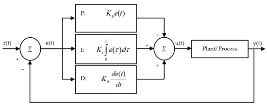
Figure 10. The diagram of a Proportional-Integral-Derivative (PID) controller.
In terms of PCM-enhanced buildings, only three types of controllers were studied. Dehghan and Pfeiffer [119] carried out a numerical study to reduce the energy consumption of a building (retrofitted with PCM on its floor), while sustaining comfort. The building incorporated PCM in the underfloor heating system. A water tank charged by either solar energy during the daytime or an electric boiler during the night was used to pump the water into underfloor tubes. The surplus of solar energy was stored in the PCM for later use. In this regard, a thermostat having a built-in P controller was implemented to switch ON the electric boiler when solar energy was not enough to maintain the comfort condition. The results showed that the application of a control strategy enhanced the performance of the proposed system for space heating.
Wu et al. [120] coupled PCM storage with a heat pump to reduce the operating cost and energy consumption of a refrigeration system used to cool a building. A PI controller was used to control the expansion valve opening and hence maintain the superheat at the evaporator exit. A dynamic model was then constructed to consider the phase transitions within the heat pump’s heat exchangers and PCM storage tank. This mathematical model could successfully predict the experimental measurements. Buonomano et al. [121] developed a model in MATLAB to predict the energy demand of buildings equipped with PCM energy storage, PV/T collector, sunspace and smart daylighting systems. The model was developed based on the energy design of non-residential Nearly Zero Energy Buildings (NZEB) under Mediterranean weather conditions. A PI control scheme was used to find the optimal design for the location of PCM in building envelop, PV/T configuration and windows topology and hence minimize the heating and cooling demand of the building. The optimum design resulted in 17% energy saving.
In addition, through Transient systems- Computational fluid dynamics (TRNSYS-CFD), a simulation-based study (Figure 11), Gowreesunker et al. [122] evaluated the energy performance of a displacement ventilation system in the departure hall of an airport. The evaluation was performed by investigating the energy demand of a displacement ventilation diffuser retrofitted with a PCM heat exchanger and comparing it with that of the diffuser-only. A PID controller was also used to control the operation of HVAC system and hence maintain the comfort temperature of the hall between 18 °C and 23 °C. The results showed that the PCM storage improved the energy efficiency of the HVAC system for cooling more than heating (34% for cooling versus 22% for heating), and a maximum energy-saving of about 34% was achieved. Cabrol and Rowley [123] used the TRNSYS simulation tool for a domestic building to analyze the thermal benefits of a concrete floor embedded PCM, in combination with an air-source heat pump for creating peak load shifting. To this end, a building with the dimensions of 12 m × 10 m × 2.4 m was provided with underfloor heating controlled by a PID controller to sustain indoor thermal comfort (at 20 °C) over 360 h in different locations of UK. The control system was designed to use off-peak tariff options, and hence minimize the costs associated with the use of the heat pump. They reported that although incorporation of PCM enhances the thermal stability of a building, its selection depends on fabric construction of buildings.
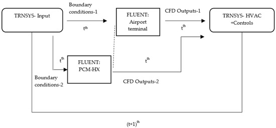
Figure 11. The diagram of TRNSYS-CFD coupled simulation [122].
-
This entry is adapted from the peer-reviewed paper 10.3390/en14071929