Microwave Kinetic Inductance Detectors (MKIDs) are superconducting low-temperature detectors for photons or particles. They are based on the change of resonant frequency of superconducting LC resonators by Cooper pair breaking and their unrivalled scalability makes them one of the most promising novel low temperature detector technologies.
- Microwave Kinetic Inductance Detectors
- kinetic inductance detectors
- MKIDs
- KIDs
- low temperature detectors
- superconducting detectors
- superconducting resonators
Microwave Kinetic Inductance Detectors: Basic Operation Principle
Every charge carrier (electrons, holes, or Cooper pairs) has a finite mass, and due to interactions with the surrounding lattice its effective mass often differs from the mass of a free electron. The term ‘kinetic inductance’ describes that (caused by this final charge carrier mass) it always takes time and energy to reverse the direction of motion of charge carriers. Therefore, when an AC voltage is applied, current will always trail behind voltage, like it does in a coil due to magnetic inductance. The size of this additional inductance in a given circuit depends on the charge carrier’s effective mass and velocity, and thus on charge carrier density. It is low for normal metals with high electron densities and a short free mean path but high for superconductors (the Cooper pair density is low in comparison) or at high AC frequencies.
In a superconductor, the interaction with the lattice leads to an attractive force between electrons, causing them to form pairs at very low temperatures. These Cooper pairs no longer act as Fermions but as Bosons, and thus will condense into the lowest state, allowing charge to be transported without resistance. The distance in energy to the next highest state is called the superconducting band gap Δ. Breaking a Cooper pair is equivalent to lifting its two electrons to the next higher state and thus requires at least twice this band gap energy. The resulting two unpaired electrons are called a quasi-particle and will recombine into a Cooper pair after a material specific quasi-particle lifetime.
MKIDs use the effect of kinetic inductance in superconductors for photon or particle detection: For an MKID, a superconductor is lithographically patterned into an LC resonant circuit (see Figure 1a), a harmonic oscillator with a well-defined resonant frequency fr = (LC)-1/2 given by its capacitance C and total inductance Ltotal = Lgeometric + Lkinetic. (Figure 1a shows a schematic for an LC-resonator with dedicated and separated inductor L and capacitor C. For many applications MKIDs follow this design using an interdigitated capacitor and a long thin superconducting line as inductor. These MKIDs are also called Lumped Element KIDs, or LEKIDs to distinguish them from quarter-wave resonators. Quarter-wave MKIDs are preferred for some applications and use a superconducting line floating at one end and grounded at the other as resonator. They have their own advantages and disadvantages for detector array design and layout but follow the same basic operation principles.) If a photon with an energy of more than twice the superconducting band gap hits this resonator, some of the photon’s energy will be transferred into heat and the rest will break Cooper pairs. This breaking of Cooper pairs by photon absorption reduces the LC-resonator’s charge carrier density and thus increases the velocity of the remaining Cooper pairs that still have to carry the same current. This leads to an increase in kinetic inductance and thus a reduction of the LC-resonator’s resonant frequency fr. This change in resonant frequency can be measured very precisely and is the signal that is monitored with an MKID to detect photons or particles.
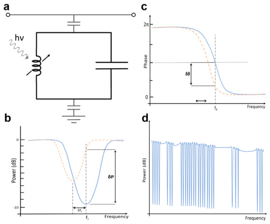
MKID resonators are capacitively coupled to a microwave feedline (which is why they are called ‘microwave’ kinetic inductance detectors) and constantly driven at their resonant frequency. The change in fr caused by photon absorption therefore shifts both the amplitude (Figure 1b) as well as the phase response (Figure 1c) of the signal transmitted on the feedline to lower frequencies. As MKID LC-resonators are superconducting they have very little electrical losses and thus a sharp resonance. Even a tiny change in resonant frequency produces a significant change in the phase signal (the sketch of Figure 1b for the amplitude signal is exaggerated for clarity, the change in amplitude is often much smaller). This phase shift can be measured quickly and very precisely, and every single photon that hits an MKID produces its own signal pulse. The pulse height is determined by the amount of broken Cooper pairs and thus the photon’s energy. For sufficient photon energy this is used to not only count single photons but also to determine their individual energies. For longer wavelengths, single photons that can still break Cooper pairs no longer cause measurable signal pulses, but the photon flux can still be measured by monitoring the shift of the MKID’s phase signal as the quasi-particle concentration will reach a flux dependent equilibrium between Cooper pair breaking and QP recombination.
As they are superconducting detectors MKIDs do have to operate at mK temperatures in most cases. As available cooling power below 1 K is small, the heat influx from the surrounding room temperature environment has to be minimized. It is therefore important to be able to monitor and read out as many pixels as possible on a single electrical line between room temperature and the detectors themselves. Herein lies the unique strength of MKIDs among low temperature detectors: They offer build-in frequency domain multiplexing. Every MKID pixel in a detector array has its individual, lithographically defined resonant frequency, usually spaced evenly over the frequency range the readout electronics can cover. As superconducting LC-resonators have very sharp resonances they do barely attenuate signals that are even just a few hundred kHz off their resonance. Many MKID resonators can thus be coupled to the same microwave feedline (see Figure 1d) without significant cross-talk. If one detector is hit by a photon and shifts in frequency the others will not react. This way it is possible to couple to and monitor thousands of MKIDs with only a few feedlines, requiring just two electrical connections to room temperature each. Up to 2000 MKID pixels per feedline have already been demonstrated and MKID arrays with up to 20,440 individual detectors are being used at the time of writing. The current limit of 2000 pixels per feedline is the result of the highest acceptable single detector resonant frequency (currently 8 GHz due to lack of very-low-noise amplifiers for higher frequencies), the fact that harmonic frequencies have to be avoided (resulting in a 4–8 GHz frequency window), and a minimum distance of 2 MHz between MKIDs in frequency space to optimize fabrication yield and time resolution.
This entry is adapted from the peer-reviewed paper 10.3390/app11062671