The aim of this study is to systematize the state of the art in the field of materials and surface modification methods used in the production of actuators. The paper discusses the requirements for the elements of actuators and analyzes the existing literature in terms of appearing failures and damages. The most frequently applied materials used in power hydraulics are described, and various surface modifications of the discussed elements, which are aimed at improving the operating parameters of actuators, are presented. The most frequently used materials for actuators elements are iron alloys. However, due to rising ecological requirements, there is a tendency to looking for modern replacements to obtain the same or even better mechanical or tribological parameters. Sealing systems are manufactured mainly from thermoplastic or elastomeric polymers, which are characterized by low friction and ensure the best possible interaction of seals with the cooperating element. In the field of surface modification, among others, the issue of chromium plating of piston rods has been discussed, which, due, to the toxicity of hexavalent chromium, should be replaced by other methods of improving surface properties.
1. Introduction
Hydraulic actuators are elements converting the energy of the working fluid into mechanical energy related to the reciprocating motion. The pressure of the working fluid acts on the piston and creates a force causing the piston assembly to move. As a result, the piston rod can perform useful work [
1,
2]. Hydraulic actuators are an executive element in power hydraulic systems. These structures have several advantages, which include the possibility of obtaining large working forces and low operating speeds [
3].
The most general division of the actuators includes single-acting, double-acting, and rotary actuators [
4]. A characteristic feature of single-acting actuators is the presence of one working chamber and the possibility of executive (active) movement only in one direction. The return movement can be carried out by an external force or a spring force. Double-acting actuators, in turn, are characterized by a working stroke in both directions.
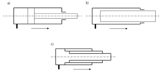
Single-acting actuators are divided into ():
Figure 1. Types of single-acting actuators: (a) piston, (b) plunger, (c) telescopic.
-
piston actuator;
-
plunger actuator;
-
telescopic actuator.
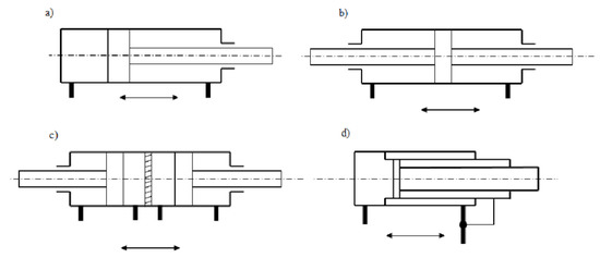
Double acting actuators are divided into ():
Figure 2. Types of double-acting actuators: (a) with one-sided piston rod, (b) two-sided piston rod, (c) multi-piston (double piston), (d) telescopic.
Piston actuators are the most common type of actuators. They are characterized by the fact that at the end of the piston rod on which the piston is mounted.
In a plunger actuator, there is the so-called plunger instead of the piston assembly. A telescopic actuator consists of a set of several pipes, extending one from the other—such an actuator allows obtaining large strokes.
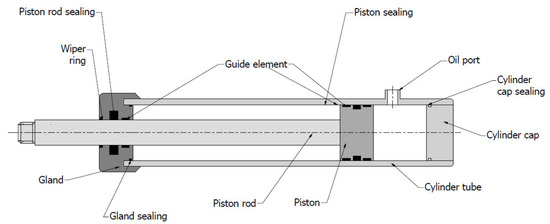
The construction of a hydraulic actuator is described on the example of the simplest piston actuator ().
Figure 3. Design of hydraulic piston actuator.
The casing of the actuator units is a cylinder tube. Inside the tube, there is a piston rod with a piston fixed at the end. On one side, the cylinder is closed by the end cap, and on the other side, there is a so-called actuator gland [
5,
6].
The cylinder cap can be assembled with a pipe using a welded connection—this is the most common way. Another method is to use a threaded cap. In the case of the latter solution, it is necessary to use a static seal to ensure adequate tightness here [
4,
5].
The piston rod is the component that transfers the load to the receiving element. The gland is usually attached to the cylinder pipe using a threaded connection, which is why sealing between the two components is also necessary here. The gland contains the entire sealing system for the piston rod. Most often there are one or two seals to prevent the working fluid from flowing outside and a wiper ring to prevent contamination from being transferred from outside to inside the cylinder. Such a sealing system contributes to increase the life of the cylinder [
5,
7,
8,
9].
There are also guide elements of the piston rod in the gland. They must be sufficiently lubricated with the working fluid of the hydraulic system. These elements absorb radial loads and hold the piston rod axially [
10].
The piston is usually connected to the piston rod using a thread connection. In this case, the sealing element must also be located here. Guide elements mounted on the piston transmit side forces and ensure that the piston is centred in the cylinder [
5,
10]. In addition to the guides, there are also sealing rings that prevent the working fluid from moving between the chambers. The piston seal acts as a pressure barrier which, for example, keeps the piston rod in a specific position [
11]. Piston seals can be single- or double-acting. The thickness of the acceptable lubricant film depends on the design of the actuator. Single-acting actuators require a small oil film; in double-acting actuators, the oil film can be slightly thicker [
10].
Hydraulic actuators are used in many branches of industry, often requiring large working forces. They are used in construction and transportation equipment (excavators, forklifts, telescopic handlers, basket elevators, booms) [
2,
12,
13]. Industries, where hydraulic cylinders are used, include mining, robotics, and aviation [
6,
14]. Therefore, manufacturers of actuators are outdoing each other in new material solutions and methods of improving the operational parameters of actuators.
To systematize the materials and surface modification methods used for hydraulic actuators elements, an extensive review of the existing literature has been made, which allowed for the preparation of a work presenting the current state of art in the field of hydraulic actuators manufacturing. This paper focuses on several of the most important elements of hydraulic actuators: pistons, piston rods, cylinders, glands, bottoms, and seals. The most common causes of failure of these parts are described, with particular emphasis on operational factors such as abrasive wear and material fatigue. Errors during the component manufacturing stage were also noted.
In the next part, the analysis of materials used for selected parts of hydraulic cylinders was performed. Material groups such as iron alloys, light metal alloys, composites, and polymers are discussed. For each of the discussed materials, the most important mechanical properties are presented, such as tensile strength, yield strength, hardness, impact energy, or elongation at break.
2. Materials and Surface Modifications Used for Hydraulic Actuator Elements
2.1. Cylinders
2.1.1. Materials Used for Cylinders
A variety of different materials are used for the cylinders, from metal materials to composites and polymers. Most often, the cylinders are made of steel or aluminum. At pressures lower than 10 MPa, cast iron cylinders are used. At pressures higher than 20 MPa, they are made of seamless steel pipe. For pressures above 20 MPa, the pipes are made of steel or forged steel [
6].
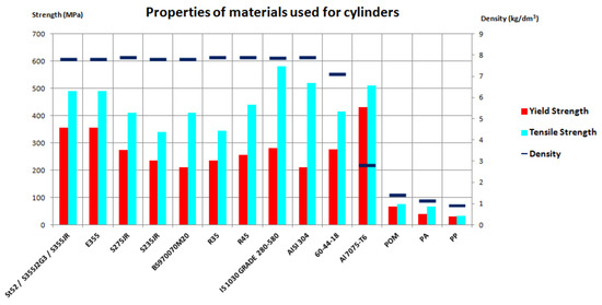
The properties of the discussed metals and polymer materials are described in and . The basic data is also presented graphically in . The chart clearly shows the difference in the density of steel and polymer materials.
Figure 6. Chart of basic properties of the materials used for the cylinders.
Table 1. Basic properties of the materials used for cylinders.
| Material |
Density (kg/dm3) |
Minimum Yield Strength (MPa) |
Minimum Tensile Strength (MPa) |
Maximum Carbon Content (%) |
Description |
| St52/S355J2G3/S355JR |
7.8 |
355 |
490 |
0.2 |
low-carbon structural steel |
| E355 |
0.22 |
low-carbon quality steel |
| S275JR |
7.9 |
275 |
410 |
0.21 |
low-carbon structural steel |
| S235JR |
7.8 |
235 |
340 |
0.2 |
low-carbon structural steel |
| BS970070M20 |
7.8 |
210 |
410 |
0.24 |
low-carbon structural steel |
| R35 |
7.9 |
235 |
345 |
0.16 |
low-carbon structural steel for pipes |
| R45 |
7.9 |
255 |
440 |
0.22 |
low-carbon structural steel for pipes |
| IS 1030 GRADE 280-580 |
7.85 |
280 |
580 |
0.25 |
non-alloy steel, general purpose |
| AISI 304 |
7.9 |
210 |
520 |
0.08 |
austenitic stainless steel |
| 60-40-18 |
7.1 |
276 |
414 |
3.4–3.8 |
spheroidal cast iron |
| Al 7075-T6 |
2.8 |
430 * |
510 |
– |
Al-Zn alloy |
| POM |
1.41 |
67–69 |
67–85 |
– |
polyoxymethylene |
| PA |
1.13 |
40 |
67 |
– |
polyamide |
| PP |
0.92 |
30 |
32 |
– |
polypropylene |
Table 2. Additional properties of the materials used for cylinders.
| Material |
Average Hardness |
Impact Energy (J) |
Elongation at Break (%) |
| St52/S355J2G3/S355JR |
180 HB |
27 (−20 °C) |
22 |
| E355 |
| S275JR |
160 HB |
27 (20 °C) |
22 |
| S235JR |
140 HB |
27 (20 °C) |
26 |
| BS970070M20 |
140 HB |
24 (10 °C) |
21 |
| R35 |
112 HB |
27 (0 °C) |
24 |
| R45 |
142 HB |
22 (20 °C) |
22 |
| IS 1030 GRADE 280-580 |
220 HB |
22 (20 °C) |
18 |
| AISI 304 |
215 HB |
60 (−196 °C) |
45 |
| 60-40-18 |
160 HB |
12 (−20 °C) |
18 |
| Al 7075-T6 |
150 HB |
17 (23 °C) |
10 |
| POM |
81 (Shore D) |
- |
30 |
| PA |
76–82 (Shore D) |
- |
20–200 |
| PP |
70–83 (Shore D) |
- |
150–600 |
One of the most popular cylinder steels is steel St 52 [
26,
27,
35]. It is steel belonging to the grade of low-carbon structural steel. It is characterized by good weldability, machinability, and does not require special treatment for both processes. This material in the context of this application is also described in the article [
62]; however, there is a designation according to European standards: S355J2G3. Similar material is also described in [
22], where it appears as S355JR. The latter two types of steel differ only permanently in the temperature of the impact test, as indicated by the mark at the letter “J.” Another equivalent of this steel, also used for cylinder tubes, is E355 [
2]. It is quality steel, often used for tubular elements.
Cylinders are also made of S275 JR [
20,
63] and S235 JR [
21]. Both have slightly lower yield strength than S355 ().
Cylinders made of another low-carbon steel are mentioned in [
45]: BS970070M20. This material is also available under a different designation: C22E. This steel was selected for testing in this article because of its appropriate yield strength and tensile strength. Moreover, its advantage is low price. Other materials used for cylinders are unalloyed steels with a special purpose: R35 or R45 [
64]. Cylinders can also be made of IS 1030 GRADE 280-580 [
65] or AISI 304 stainless steel [
21]. The latter, however, is used for special applications or those working in difficult conditions.
In the article [
66], an analysis of a selection of suitable material for the cylinder pipe was carried out. After establishing requirements such as corrosion resistance, high strength, low density, good machinability, and low cost, the most optimal material was selected: spheroidal cast iron 60-40-18. It is a good choice in hydraulic systems with relatively low working pressures. Moreover, the use of cast iron allows avoiding noise caused by excessive vibrations, as this material, like any cast iron, has the ability to dampen them [
67].
Apart from ferrous materials, the tendency to reduce mass determines the use of light metal alloys, e.g., aluminum, for cylinders. In [
68], AlZnMgCu cylinders are mentioned—this is a group of aluminium alloys, in which zinc is the dominant additive. To this group belongs the material Al 7075-T6, which was described in many articles.
In [
21], the steel materials were compared with Al 7075-T6 and a composite material consisting of 40% epoxy resin and 60% carbon fibers. Comparing the cylinder made of structural steel and this composite material, the mass was reduced by as much as 96% while maintaining appropriate mechanical properties. Unfortunately, the price of the composite cylinder is even several times higher than for the other materials tested. A good solution seems to be the use of aluminum, which reduces the weight of the cylinder by 91% compared to steel, and in economic terms, it more than doubles the price of the cylinder.
In [
22], it was noted that the change of material from structural steel to Al 7075-T6 resulted in a significant reduction of the cylinder weight, which had a positive impact on the degree of the ecology of the hydraulic system as well as on its power demand. In [
63], similar tests were carried out, but here the Al 7075-T6 aluminium pipe was wrapped in a composite consisting of epoxy resin and carbon fibers with the same proportions as in [
21]. Such a solution was chosen to avoid damage caused by seals slipping on the inner surface of the pipe. A similar construction was also discussed in works [
19,
20].
In [
69], the pipe is made from a thin S355 steel insert on the inside and is wrapped with CFRP (Carbon Fiber Reinforced Polymer) on the outside. The use of the insert was to provide the sealing system with appropriate tribological working conditions. This approach reduced the weight of the cylinder by several dozen percent. CFRP material has high strength, is resistant to corrosion and fatigue. Additionally, it has a low density. As the name suggests, it consists of carbon fibers embedded in a polymer resin, in which the carbon fibers act as a strengthening material and the polymer resin acts as a matrix holding the fibers [
70]. The article [
71,
72] also discusses the application of CFRP to hydraulic cylinders. The paper [
71] points out that the application of the composite for the cylinder pipe will allow for significantly reducing the weight; however, it will bring additional tribological problems in the piston-cylinder contact, hence the need to find a suitable method of manufacturing such cylinders. In the article [
72], it was noted that in some situations steel inserts in a polymer tube may be damaged due to critical stress caused by the difference in mechanical properties of the metal and CFRP. The article notes the necessity of stiffening the structure. The application of nanostructured epoxy resin gelcoat made of Al2O3 nanoparticles inside a multilayer CFRP cylinder was proposed as a method. The inner surface of such a cylinder proved to be very durable.
The article [
73,
74] present prototypes of cylinders made of POM (polyoxymethylene) plastic. Such an approach was explained by many advantages of this type of materials: reduction of weight, an increase of vibration damping, and thus reduction of noise and nuisance to the environment. POM plastic shows adequate mechanical strength and heat resistance. Plastics can provide better tribological properties and resistance to aggressive environments.
In [
75], the use of polyamide (PA) and polypropylene (PP), of which prototype hydraulic cylinders are made, is described. PA is a polymer with good mechanical properties and abrasion resistance, but can, unfortunately, absorb water. In turn, PP is a material characterized by chemical inertia and very good fatigue strength [
76].
2.1.2. Surface Modifications of Cylinder
The inner surfaces of the cylinders are ground and honed to achieve a smooth surface. However, sometimes machining proves to be insufficient. The performance of most steels used for hydraulic cylinders is improved by additional surface modification.
In [
64], the technology of production of hydraulic cylinders is described, which is a combination of machining and forming (burnishing). Burnishing can be carried out with simultaneous rolling of the sleeve or after the manufacturing process. It enables to skip the honing stage. Burnishing allows obtaining high smoothness of the surface layer and additionally strengthens it. The surface becomes more resistant to abrasive wear and fatigue. The pressing process is also economical as it can be carried out simultaneously with other processes.
The properties of the steel used for cylinders, such as hardness, can also be improved by carburizing [
45]. After the carburizing process, hardening is carried out, which directly leads to increased resistance. The surface layer of the steel becomes wear-resistant and retains its mechanical properties at the same time [
77].
For special applications, the inner surface of the cylinder can be chrome plated—this is the case with telescopic cylinders, for example. Such a coating makes it possible to give it abrasion resistance. Its other properties and the reasons for the gradual abandonment of this technique are described in more detail in
Section 4.3.2.
In [
24], the application of n-Al
2O
3/Ni–Co nanocomposite coatings on hydraulic cylinders by brush plating was mentioned to increase their resistance to wear.
Hydraulic cylinders can also be coated with zinc or tin coatings on the outside. The main role of such coatings is to give protection against corrosion. This is especially important for cylinders working outside and exposed to adverse weather conditions.
In [
78], the application of DLC (Diamond-Like Carbon) coatings on hydraulic actuator tubes is also mentioned. These coatings are resistant to harmful substances, characterized by low friction coefficient and high hardness as well as resistance to wear and corrosion.
2.2. Pistons
The pistons are usually made of steel or cast iron [
4]. It must be a high-quality material to allow for the longest possible trouble-free operation.
In [
79], spheroidal cast iron 65-45-12 for piston application is mentioned. It is a good alternative to carbon steel. The graphite content facilitates processing. Furthermore, ductile iron is lighter than steel.
The pistons of hydraulic cylinders can be made of C35 or C45 steel [
6]. These are unalloyed steels that are very easy to heat treat, but difficult to weld. Other steels are S275 JR [
63], S 355 JR [
22], and BS970070M20 [
45]. These are structural steels already mentioned in the hydraulic cylinders. Stainless steels are used for pistons (e.g., in special purpose cylinders) [
80].
Apart from ferrous materials, light metals such as Al 7075-T6 [
63,
69] are also used in the context of this application.
Currently, research is being conducted on the application of composite and polymer materials in pistons. The article [
73] proposes a piston from POM.
Pistons are rarely subject to surface modifications. Sometimes it is possible to improve their surface parameters by applying DLC coatings [
78].
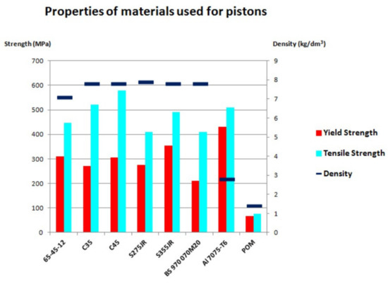
The basic data is also presented graphically in .
Figure 7. Chart of properties of the materials used for the pistons.
2.3. Piston Rods
2.3.1. Materials Used for Piston Rods
The piston rod, as a quite demanding element, must be made of good quality material with appropriate parameters. Both unalloyed and alloyed and even stainless steel are used for the piston rod.
In [
21], S235 JR steel is used for the piston rod. In [
63], steel with a slightly higher yield point was selected: S275 JR. In [
81], the use of other structural steel was described: S355J0. Its other designation is 18G2A.
Many papers discussed piston rods made of steel C45 [
43,
44,
82,
83]. In [
6], apart from the mentioned steel, C35 is also used, and if the influence of vibrations is high, even C55 or 40Cr. In [
84], piston rods made of the equivalent steel 40Cr, 40X are used. In [
1,
38], C45E is used.
The steel commonly used for the piston rod can also be 40HM (42CrMo4) [
42,
69,
81]. Other materials are 20MnV6 [
85], 19MnVS6, 38MnVS6 [
1], or 30CrNiMo8 [
70]. BS970070M20 [
45] and similar BS970070M55 (other designation: C55E) [
40] are also applied.
For more demanding applications, stainless steel is used. These are 17-4PH [
41], AISI 304 [
21], and AISI 410 [
39]. The latter belongs to the group of martensitic steels, which are mechanically durable and at the same time resistant to corrosion. Their resistance depends strictly on chromium and carbon content and processing conditions. Unfortunately, these materials belong to the group of soft steels [
86].
Apart from steel, piston rods can be made of aluminium alloys [
68]. In [
20,
21,
63], the piston rod is made of Al 7075-T6. In [
73,
74], the piston rod is made of POM. Another material, still in the testing phase, is a composite of epoxy resin and carbon fibers [
21].
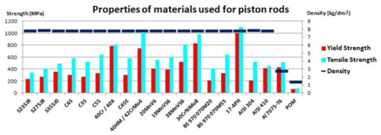
The basic data is also presented graphically in .
Figure 8. Chart of properties of the materials used for the piston rods.
2.3.2. Surface Modifications of Piston Rods
The surface of the piston rod is modified very often by heat- and heat-chemical treatment or by coating.
In [
40,
87], quenching and tempering was proposed as a treatment for the piston rod. Improvement is a process of combining hardening and high tempering. Its aim is to achieve high impact strength and ductility with appropriate hardness and strength values [
88].
In [
89], there is talk about induction hardening of the hydraulic cylinder piston rod. This method allows increasing surface resistance to damage. In [
41], the precipitation hardening was proposed to improve the surface parameters of the piston rods and obtain high strength of the layer.
Among the coatings, a definitely basic modification is hard chromium plating [
4,
9,
38,
50,
84,
90]. Such a coating is applied electrolytically in a bath [
91]. The action of direct current causes the deposition of metal ions of the coating on the steel surface.
Chromium plating allows obtaining a coating resistant to wear and corrosion, even in aggressive environments. The hard chrome layers are characterized by high hardness and low friction. However, the accuracy of application is important, as there is a risk of micro-cracks weakening the properties of coatings [
92]. The solution may be to apply a layer of nickel under the chromium layer, which additionally improves the corrosion resistance [
38].
Unfortunately, chromium coatings have their disadvantages. Already during the coating process, there is a risk of chrome poisoning by the process personnel. This metal is toxic and may cause respiratory damage, asthma, or cancer [
93]. The process absorbs large amounts of energy and generates dangerous waste, which is difficult to utilize [
94]. In many countries, it is recommended to abandon hexavalent chromium coatings by standards introducing limits for this element or completely banning its use in some applications [
95,
96,
97]. Hence, there is a need to find alternatives to this method of surface modification.
The issue of alternative surface modifications is described in detail in the article [
95]. The main method is the use of one of the varieties of thermal spraying—HVOF (High Velocity Oxygen Fuel) process, which can give corrosion and wear resistance even better than galvanic chromium plating. This method is based on the fact that the particles of the applied material are raised in a gas stream with a speed several times higher than the speed of sound. Such high speed allows limiting unfavourable changes in the chemical composition of these particles. Accelerated particles affect the surface of the substrate and result in a coating [
77,
98]. This method can be used to obtain homogeneous coatings with low porosity, good adhesion to the substrate, and high strength. The process is more efficient than galvanic chromium plating and does not produce so much waste. However, the cost may be even twice as high as for electrolytic chromium plating [
94,
95,
97,
99].
Examples of coatings used on piston rods produced by HVOF and giving similar features as electrolytic chrome plating are: WC-10Co-4Cr, Cr
3C
2–NiCr, and WC/Co/Cr [
95].
Another alternative is APS (Atmospheric Plasma Spraying). The process allows obtaining coatings of similar structure and porosity to HVOF. It consists of melting the material for the coating in electric arc plasma [
77]. In the case of plasma spraying, it is possible to combine materials in one layer and control the parameters of the coating relatively precisely. Plasma spraying has the advantage over HVOF that it can also be used for internal surfaces, such as cylinders. Coatings that can be applied to the piston rod using the APS method are, e.g., Cr
2O
3–SiO
2–TiO
2 [
95].
HVOF coating as an alternative to chromium plating is also given in [
83]. The possibility of applying Fe/TiC coatings produced with HVOF to the piston rods was investigated, and its properties were compared with hard chromium coatings applied electrolytically and with WC/CoCr coatings applied with HVAF (High Velocity Air Fuel) process. Studies have shown that Fe/TiC coatings showed similar anti-wear and anti-corrosion properties as the reference coatings, but their application was much more economical. The method of thermal spraying for modification of the piston rod surface was also mentioned in [
87].
In [
100], it was noted that the application of protective layers melted from cored wires (CW) under the flux layer is more ecological and economical than galvanic chromium plating. The article examines different layers embedded in the mentioned technology, differing in phase structure. It was shown that with an increase in the percentage of ferrite in the structure, the corrosion resistance of the austenitic matrix increases. Among the investigated coatings, the most resistant to corrosion turned out to be the core wire coating with an only ferritic matrix structure.
In [
50], the application of CVD (Chemical Vapour Deposition) and PVD (Physical Vapour Deposition) coatings, laser coating, and thermal spraying were indicated as an alternative to chromium plating. Surface treatment technologies are also proposed as a combination of gas nitrocarbonation, plasma nitrocarbonation, and oxidation. This provides a layer that protects against corrosion and wear and has tribological parameters. Nitrided piston rods were also mentioned in [
81].
In [
101], it was proposed to apply a nanostructured tungsten carbide coating deposited with CVD on metal elements in contact with seals in order to minimize possible leaks, among others in actuators. Such a coating allows obtaining high resistance to abrasion and corrosion and general protection of surface roughness parameters of the substrate. All this has a positive effect on the durability of seals. It has been noted that this coating can also be a very good alternative to hard chrome coatings.
In [
24], as an alternative to chromium coatings on the piston rod, a n-Al
2O
3/Ni–Co nanocomposite coating produced in the process of brush plating was proposed. This method belongs to galvanic methods. It can be used to repair damages in chromium plated piston rods. Such a coating gives much higher wear resistance and is tribologically similar to hard chromium coatings.
In [
44], the method of repairing piston rods that have been corroded by powder welding (Plasma-Powder Surfacing) with a Fe–C–Cr–V coating is described. Conventional arc welding (AS, Arc Surfacing) could not be applied due to the risk of deformation of a relatively small diameter bar. Corrosion-resistant material, chrome-vanadium cast iron 315Kh19F3 grade was used as a padding weld.
In [
25], the application of DLC coatings for hydraulic actuator components, which are covered by the concept of sliding motion, was examined. An example of such an element is the piston rod. In [
78], the application of DLC coatings for the piston rod of a hydraulic cylinder used in construction machines was mentioned. It was related to very good parameters of these coatings in terms of resistance to wear and aggressive environment [
23].
In [
102], the DLC coating was compared with TiN coating. Both are characterized by high mechanical strength. TiN has better wear resistance, but DLC has better tribology and corrosion resistance.
2.4. End Caps and Glands
Glands and end caps of hydraulic actuators are described and tested relatively rarely. Both of these elements are indirectly responsible for the tightness of the actuator, so great care must also be taken to manufacture them.
The caps are often made of the same material as the cylinder. This can be low carbon steel S355 [
69], S355 JR [
2], or S275 JR [
63]. In [
20,
63], Al 7075-T6 alloy is additionally proposed for this element.
In the work [
65], IS 1030 GRADE 280-580 was used for the cylinder cap. In [
45], BS970070M20 was proposed. The article [
4] also mentions the cast iron caps. Quite a modern and still being tested material is POM [
73,
74]—such elements are used for cylinders made of plastic.
As far as the gland is concerned, it can be made of steel or aluminum. The gland made of S275 JR steel is described in [
63]. In industry, these parts are also made of C45, 42CRMo4, AISI 304, or G25 cast iron.
Aluminum Al 7075-T6 for glands was used in [
20,
63,
69]. In [
73], the application of POM type plastic is mentioned.
When it comes to surface treatment, glands can sometimes be modified with chromium-containing coatings, which protect the elements against corrosion [
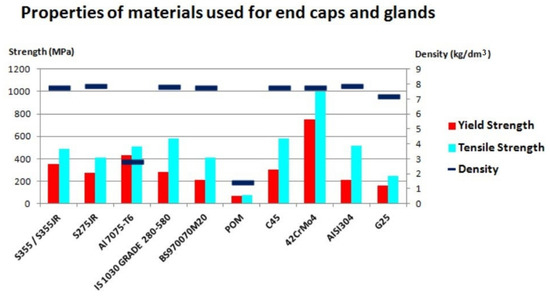
95]. The basic data is also presented graphically in .
Figure 9. Chart of properties of the materials used for the end caps and glands.
This entry is adapted from the peer-reviewed paper 10.3390/ma14061422
