The reconfigurable vectorial thruster (RVT) is a propulsion element that changes not only the intensity of the thrust vector but also its direction. This vector reorientation by a servomotor, for example, is usually faster than the intensity change. Thus, the possibility of fast vehicle reconfiguration allows the optimized choice of the reconfigured propulsion architecture according to different tasks, minimizing the trajectory tracking error and energy consumption. Moreover, the use of RVTs can significantly reduce the total number of needed thrusters in a vehicle.
- underwater propulsion
- underwater robots
- vectorial thrust
1. Introduction
In our globe, biologists have expanded the use of drones for research in dense forests, and institutions are adopting such vehicles for their monitoring with the intention of preserving these areas. Moreover, rivers and oceans are also explored through remotely operated underwater vehicles (ROV) or more recently by autonomous underwater vehicles (AUV).
Beyond the Earth limits, humanity is feeding other ambitions in the NASA’s project SUBSEA [3], which aims to find extraterrestrial life through the exploration of hydrothermal systems of underwater volcanoes, in a hidden ocean beneath the icy crust of Saturn’s moons Enceladus and Europa.
Nevertheless, the use of underwater vehicles is not only restricted to scientific research interests. Since the last decades of the XXth century, autonomous robots are used in other tasks where the activity of divers is costly, dangerous or even impossible. There is an important interest in these robots for the maintenance of marine renewable energy (MRE) systems (underwater devices such as offshore wind turbines, tidal power plants, or hydroelectric dam underwater structures). Moreover, there are also interests in military applications (mine warfare, sensitive areas protection, identification of magnetic and electric boats signatures), port activities (monitoring of installations, inspection and maintenance of ships hull), or maritime safety (pollution control, search for wrecks, emergency response to submarine disasters), and for offshore industry activity (pipelines or telecommunication cables).
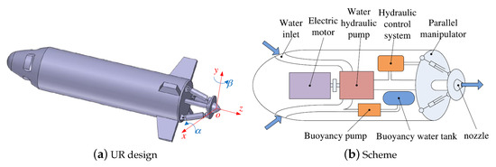
For all these missions, underwater interventions on complex geological or fabricated architectures—which are usually obstacle infested and hostile environments—require fully autonomous underwater vehicles (AUVs) with advanced key technologies [4], as enhanced manoeuvring capabilities [5], controlled with the most intelligent algorithms. These more stringent demands imply the need to expand the capabilities of AUVs such as speed, power, control, perception, autonomy, and depth [6]. However, the propulsion and control systems for this robot kind have not improved as quickly as their needs, which restricts their performance and thus their autonomy. According to [7], it is necessary to give long-range and manoeuvring capabilities to AUVs to advance to a new generation of underwater robots (UR) able to perform a more extensive set of operations. What refers to two design aspects of these vehicles: hull shape (e.g., torpedoes have a streamlined shape to favour hydrodynamic penetration) and propulsion system. In [5], it is observed that investigations and developments have been conducted about underwater vehicles locomotion, but few are dedicated to the propulsion system itself.
2. Formal definition
The propulsion systems of underwater vehicles can be divided into four categories:
-
Classical rear propeller with control surfaces [8,9,10,11,12,13,14,15], Figure 1
-
Biomimetic and bioinspired propulsions [16,17,18,19,20,21], Figure 2
-
Vectorial thrust (VT) given by fixed or reconfigurable thrusters (FT or RT) [22,23,24,25,26,27,28,29,30,31,32,33,34,35,36], Figure 3 and Figure 4
-
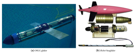
Underwater gliders, floats, or hybrids [36,37,38,39,40,41], Figure 5
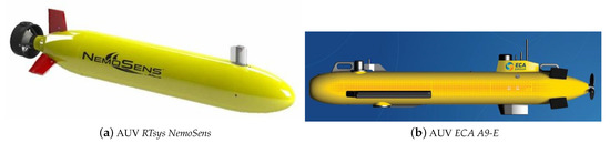
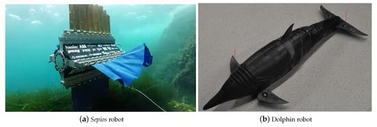
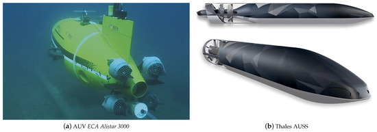
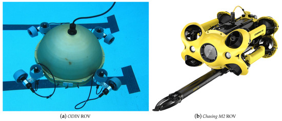
Figure 4. Examples of robots with fixed vectorial thrusters [32,42,43].
It is immediate that the propulsion architecture of a vehicle determines its set of possible motion directions, as well as influences the ability to control the movement.
In VT propulsion systems (Figure 3 and Figure 4), it is possible to drive and steer the vehicle only using thrusters through various strategies. A single fixed thruster (FT) endows the robot with only a thrust vector \( \mathbf{F}_T \) (with fixed direction in Figure 6), which does not allow trajectory tracking. This issue is solved with the combination of several FTs acting in different directions and with different thrust vectors \( \mathbf{F}_T \), placed differently by a position vector \( \mathbf{r}_C \), as in robot ODIN [42,43] (Figure 4a), which can be considered the first underwater robot with a full holonomic propulsion [48]. Another newest possibility is to use a few or a single reconfigurable thruster (RT) [26], since they may have their thrust vectors redirected, which involves more than one degree of freedom (DOF) per thruster, and so, an integrated solution for propulsion and guidance [27].

In terms of manoeuvrability that is the heart of this paper, classical rear propeller with control surface architectures are less manoeuvrable because the control action is reactive and indirect since the vehicle cannot be steered if there is no advance. Underwater gliders are still less manoeuvrable since their rudders are not controllable. Biomimetic and bioinspired propulsions can reach great manoeuvrable architectures but usually requiring many DOFs of actuation. Vectorial thrust using fixed thrusters (FT) can be highly manoeuvrable if equipped with many thrusters, sometimes greater than 6 as in ROV ODIN [42,43] (Figure 4a). The propulsion architecture is so endowed with many thrust vectors in different directions and the control system works to define the correct intensity of each one. It results in a total force and torque propulsion vectors, respectively \( \mathbf{F}_P \) and \( \mathbf{M}_P \), shown in Figure 6. Vectorial thrust using reconfigurable thrusters (RT) can significantly reduce the total number of thrusters. It is possible because, not only the intensity of vectors are changed but also their directions in this type of propulsion architecture. Moreover, the vector reorientation by a servomotor, for example, is usually faster than the intensity change. Moreover, the possibility of the robot reconfiguration allows the optimized choice of the reconfigured propulsion architecture according to different tasks, minimizing the trajectory tracking error and energy consumption [49].
Figure 6 presents a 2D model for the vectorial thrust approach. In this figure, the vehicle thrusters are propeller-based. However, VT propulsion type includes also jet-based thrusters, which is a convergence point with bioinspired robots, as it is possible to see in the jellyfish [50].
In Figure 6, the vehicle has to follow a defined trajectory keeping the desired orientation. For that, temporal needed efforts \( \mathbf{F}_N(t) \) and \( \mathbf{M}_N(t) \), in the centre \( C \), are calculated. However, the vehicle is under ocean efforts that also changes along the time, represented by \( \mathbf{F}_O(t) \) and \( \mathbf{M}_O(t) \), acting in point \( C \). Hence, to follow the given trajectory with the desired orientation, the vehicle propulsion system has to calculate and generate, continuously, the propulsion vectors defined as:


and

3. Advances in Reconfigurable Vectorial Thrusters
The penetration of VT technology in commercial AUVs is verified more by the adoption of FT-based architectures than RT ones. It is due to the intrinsic complexity in terms of mechanism making of RTs. Moreover, RT control systems are harder than FT ones that can use known PID strategies since the relation command-torsor is linear, which is not the case with RTs. FT industrial examples are found in the ROV Victor 6000 [28], the AUV ECA Alistar 3000 [22] Figure 3a, and the AUV ECA A18-TD [29]. New personal portable underwater drones for photographies usually are FT-based as in drones Chasing F1 [30], M2 [31], Dory [32], Gladius Mini [33], and the drone PowerRay [34]. A military example of an advanced RT-based prototype is the autonomous underwater and surface system (AUSS) from Thales Group [25] (Figure 3b).
One of the RT systems advantages over FT ones is the possibility of reducing the number of thrusters to the minimum, which reduces the total vehicle mass and volume. Another advantage is the possible reduced consumption of energy when changing directions [7] since, in most options, it is only necessary to change the orientation of the propeller or duct. However, to guarantee a greater manoeuvrability and increased controllability of AUVs, an RT must be endowed with the highest possible capability to reorient its thrust vector [51]. This means a great angle range and more DOF per thrusters.
In the last two decades and more intensively in the last one, researches have been carried out to advance in the development of different RT types. The advance in RT propulsion can be divided into two groups: propeller-based and pumped-water-jet-based RTs. Moreover, other RT characteristics can organise them in other groups. For example, between options where only the water flux has its direction reoriented by ducts or nozzles, or options where the pump or propeller with their motors have to be reoriented as well. The latter aspect is relevant for the inertia analysis, which determines needed forces, torques, and power-supply for a fast reconfiguration.
Another indispensable question is how many ideas were converted in submersible prototypes. It is a crucial point since RT thrusters with 3-DOF are sometimes equipped with a parallel mechanism that depends on 4 actuators, and most of the proposals do not address the water-tightness issue in transmitting all these movements outside the robot hull. Most of the works present different RT architectures for studying different control strategies, but the construction feasibility is not addressed. Below, some relevant RT architectures propositions are chronologically presented, and they are highlighted every time a proposal comes with a submersible prototype.
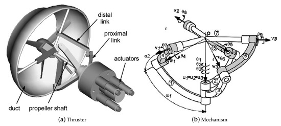
In [52] (2000), an RT in a “MicroAUV” is presented, with the water-jet reorientation reached by its tail reconfiguration. In [27] (2004, Figure 7), an RT is developed with 3-DOF of the duct and propeller reconfiguration, using a spherical parallel mechanism with 4 actuators (one for the main power transmission and the other three for the reconfiguration).
In [51] (2008), the concept of a propeller-based reconfigurable magnetic coupling thruster (RMCT) is introduced, modelled, and experienced.
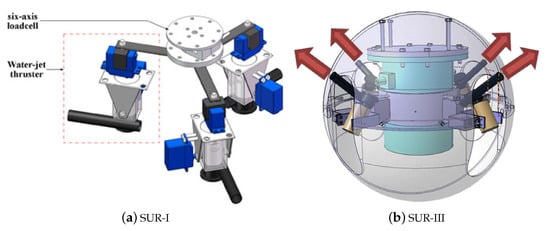
In [53] (2009), it is introduced a novel architecture with three pumped-water-jet-based RT, each one with 2-DOF controlled by two servo-motors. Here, the jet force is not a DOF associated since the water-jet pressure is constant. After one year, it is possible to see the evolution of this concept in [54] (2010), where the architecture concept with three pumped-water-jet-based RT evolved for a prototype in construction. And, finally, a real spherical underwater robot (SUR) is presented with the three pumped-water-jet-based RT in [55] (2012, see Figure 8a).
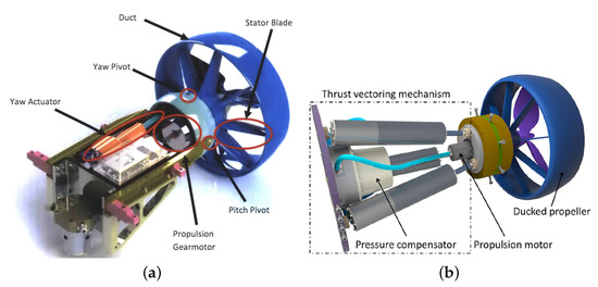
In the same year, in [57] 2012, the prototype of the MASUV-1 robot is presented (Figure 9). MASUV-1 is a small real underwater vehicle with an RT-based on nozzle orientation that redirects the propeller flow with 2-DOF (total of 3-DOF), keeping the propeller out of reach of marine life, and not requiring any shaft reorientation. It is interesting to note in MASUV-1 propulsion technology how concepts of water-jet and propeller-based RTs are combined. The range of reconfiguration of MASUV-1 is equal to \( [-16^{\circ},16^{\circ}] \) for both reconfiguration angles.
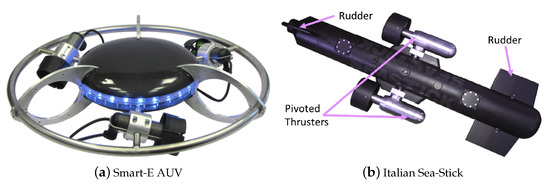
In [58] (2013, see Figure 10), similarly to [53] (2009), a pumped-water-jet-based RT is presented, using three actuators to assure more 2-DOF of reconfiguration to the thrust. In the same year, two propositions were published showing the application of RTs in two different propulsion architectures (see Figure 11): the Smart-E AUV [59] and the so called Italian sea-stick [60] apud [61]. In these publications, RTs are called pivoted thrusters. The Smart-E AUV realizes a holonomic drive with only three thrusters. The Italian sea-Stick is a hybrid solution since it is also equipped with rudders.
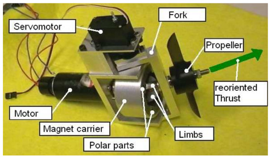
In [5] (2014, see Figure 12), the RMCT concept presented in [51] (2008) evolves for a non-submersible prototype, using a spherical reconfigurable magnetic coupling (S-RMC) or joint, with one actuator to assure 1-DOF of reconfiguration.
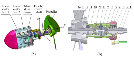
In [4] (2015), authors analysed the state of the art in key technologies for AUVs and indicate that the RT technologies were not yet mature and so, they propose a 3-DOF orientable motor-to-propeller transmission mechanism (see Figure 13), based on ball gear, with wide range wrist rotation. However, their review did not take into account advances in the RMCT concept, since they analysed only water-jet and mechanical transmission systems. In [62] (2017), more details are shown about the motor-to-propeller transmission mechanism, based on ball gear. The design shows a range of reconfiguration near to \( [-90^{\circ},90^{\circ}] \) for both reconfiguration angles. However, in the test photos, this range seems closer to \( [-60^{\circ},60^{\circ}] \).
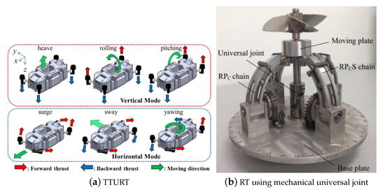
In [63] (2015, see Figure 14a), a tilt thrusting underwater robot (TTURT), equipped with four thrusters, each one with a total of 2 DOF (considering that the thrust intensity control is a DOF in itself). It is interesting to note that TTURT thrusters adapt a commercial thruster (Seabotix BTD-150) in a reconfiguration system, including one more DOF. However, all the thruster‘s body has to be rotated, including propeller, duct, and even the motor and gear.
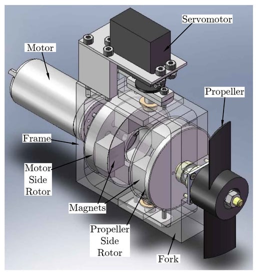
In [65] (2016, Figure 15), the RMCT concept presented in [5,51] receives a new non-submersible prototype, using now a flat reconfigurable magnetic coupling (F-RMC) or joint, also with one actuator to assure 1-DOF of reconfiguration.
In [56] (2017, see Figure 8a), the SUR-II evolves to the SUR-III, now with four three pumped-water-jet-based RT, each one with 2-DOF of reconfiguration, using waterproof servo-motors.
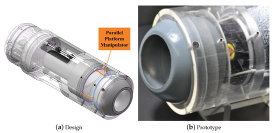
Robots with torpedo-shaped hulls are proposed in [64,66,67] (see Figure 14b and Figure 16). They are equipped with propeller-based RTs, with 2-DOF of reconfiguration, using a different type of spherical joints. The difference between them is in the reconfiguration mechanism. In [67] (2019), a parallel mechanism with three actuators is necessary for controlling two more DOF, as in [27,58]. In [64] (2016, see Figure 14b), 2-DOF of reconfiguration are added using only two actuators, as in [57,62], but this time using a spherical robotic wrist joint proposed in [68,69].
The usage of magnetic coupling to ensure the water-tightness of FT systems is not new [72,73]. The novelty in RMCT [51] is the use of reconfigurable magnetic couplings to construct feasible RTs.
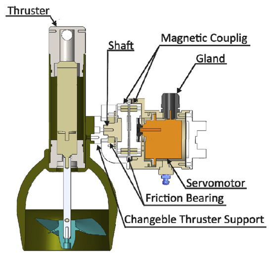
As discussed, RTs are endowed with at least 2-DOF of actuation, which means the thrust vector can be contained in a plan. Figure 17 shows a section view of a 2-DOF RMCT [61].
This entry is adapted from the peer-reviewed paper 10.3390/jmse9020170