: In the last decade, the friction stir welding of polymers has been increasingly investigated by the means of more and more sophisticated approaches. Since the early studies, which were aimed at proving the feasibility of the process for polymers and identifying suitable processing windows, great improvements have been achieved. This owes to the increasing care of academic researchers and industrial demands. These improvements have their roots in the promising results from pioneer studies; however, they are also the fruits of the adoption of more comprehensive approaches and the multidisciplinary analyses of results. The introduction of instrumented machines has enabled the online measurement of processing loads and temperature, and critical understanding of the principal aspects affecting the material flow and welds quality. Such improvements are also clearly demonstrated by the increase of the strength of recent joints (up to 99% of joining efficiency) as compared to those reached in early researches (almost 47%). This article provides a comprehensive review of the recent progresses on the process fundamentals, quality assessment and the influence of process parameters on the mechanical behavior. In addition, emphasis is given to new developments and future perspectives.
- polymers, joining, friction stir welding
Description of the Main Phases
Friction stir welding can be performed to produce continuous and spot welds. In this latter case, the process is called friction spot stir welding (FSSW). During FSSW, the tool simply plunges the sheets placed in lap configuration upon a certain amount of material around the tool stir leading to the formation of the bond. Friction spot stir welding can be ideally subdivided into four phases, namely: plunging, dwell, cooling and punch retraction. During the plunging phase, the tool, which rotates at a prescribed speed, is plunged against the upper sheet and the probe tip reaches the lower sheet. The material moved by the tool probe extrudes vertically in form of ejected material. If the prescribed depth is reached, dwell starts and the plunge motion is stopped, while the tool continues to rotate. This phase is aimed at heating the material surrounding the tool probe where the connection between the sheets is formed. At the end of the dwell, cooling starts. This phase consists into stopping even the tool rotation. This enables the materials to cool down. This phase can be performed by holding the vertical position of tool, or under load control. This second way was demonstrated to have the capability to close the porosities and cavities that commonly form at the interface at the stirred region and surrounding material [74]. This can lead to superior mechanical behaviors of the welds. As the material has sufficiently cooled down, the tool is retracted. However, if this is performed prematurely, the retraction can lead to a tearing out effect of the material surrounding the tool [75], or even to material attached to the tool [76], as shown in Figure 23. A schematic of the main phases of FSSW is reported in Figure 23.
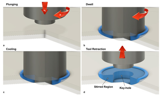
Figure 23. Main phases of FSSW development: (a) plunging; (b) dwell; (c) cooling and (d) tool retraction.
Material Flow
Compared to metals, polymers are characterized by much lower thermal diffusivity and higher temperature sensitivity. This promotes the development of steep thermal gradients, which in turn determine regions with great differences in terms of mechanical behavior. Consequently, after a first contact between the tool and the upper layer, a thermo-mechanical affected zone immediately develops in the region underlying the tool probe, as shown in Figure 24b.
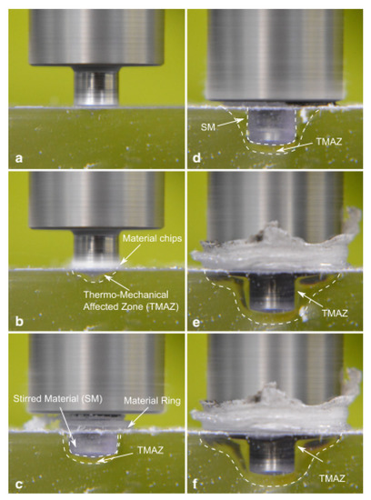
Figure 24. Material flow during FSSW of transparent polymers: (a) initial position; (b) formation of chips; (c) formation of TMAZ under the tool pin; (d) enlargement of the TAMZ; (e) deep plunging and (f) material after dwell.
The material underlying the tool probe (TMAZ in Figure 24b,c) is characterized by a much higher temperature compared to the surrounding and underlying regions. Thus, it rapidly starts to reflow (reverse extrusion) vertically, as shown in Figure 24c. The TMAZ region extends progressively as the process proceeds, as the longer interaction time. This region also undergoes a drastic morphological change from a “U-shape” to “V-shape” as the tool shoulder approaches the upper surface of the upper sheet, as shown in Figure 24d. This owes to the contact of the tool shoulder with the polymer that leads to higher frictional heat and higher amount of material flow. The change to the “V-shape” of the TMAZ produces a dramatic increase of the mechanical behavior of the welds as it involves an increase in the extension of the weld area. Similarly, further plunging of the tool enables a downward shift of the TMAZ, which contributes to enlarge the weld area. During the dwell phase, the prolonged interaction time, which determines an increase of the frictional heat, also contributes to enlarge the welded region. This owes to heat diffusion effects that tend to increase the temperature of surrounding regions. The following cooling phase occurs. This is mainly aimed at enabling the tool retraction as soon as the material has restored its mechanical properties with a temperature well below the melting and softening temperatures of the polymer. Then, the tool is retracted. This comes with the formation of a blind hole in the joint (weld nugget) that is left by the tool probe.
As a result, the geometry of the friction spot stir welds can be characterized by the weld nugget, the stirred zone and the material reflow. This last feature is generally removed by common machining operations such as milling or drilling. On the other hand, the geometry and dimension of the weld nugget and stirred material determine the mechanical behavior of the welds. The characteristic dimensions of friction spot stir welds are reported in Figure 25.
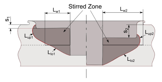
Figure 25. Effect of plunging depth on geometry of the weld [77].
Morphology of the Welds and Quality Assessment
To better comprehend the influence of the process parameters on the mechanical behavior of the welds, a deep analysis of the morphology of the joints and its influence on the failure mechanisms is required.
Figure 26a schematized an FSS weld as the connection of three regions: the upper sheet, the lower sheet and the stirred region. Although the upper and lower sheets are characterized by thermo-mechanical affected characteristics, they show their original compactness. On the one hand, the stirred region is often characterized by a certain porosity. This is mainly due to air trapped within the material during the process, as well as moisture of the original material in case of highly hygroscopic materials [78]. On the other hand, at the boundary of the stirred region with both the upper and lower sheets, bubbles and porosities can be highly concentrated. This is due to the thermal shrinkage of the material during the cooling phase. Steep temperature gradients develop between the stirred region and surrounding areas owing to the low thermal diffusion of polymers. Thus, the stirred region is at much higher temperature; consequently, during the cooling phase, the stirred region shrinks more than the upper and the lower sheets. This may cause the formation of a porous interface between the stirred region and the surrounding areas, as shown in Figure 27.
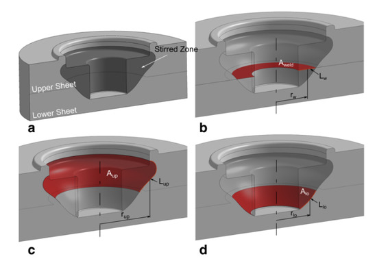
Figure 26. Characteristic interface areas of friction stir spot welds [74]: (a) stirred zone; (b) Aweld; (c) Aup and (d) Alow.
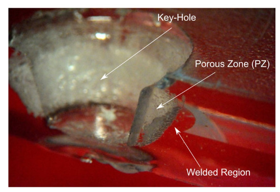
Figure 27. Presence of porous region at the interfaces between the stirred region and upper and lower sheets [77].
The failure of the FSS welds may occur in different ways, namely:
- Brittle fracture in the upper sheet (M1);
- Brittle fracture in the lower sheet (M2);
- Separation of the SZ from the lower sheet (M3);
- Separation of the SZ from the upper sheet (M4);
- Shear fracture in the SZ (M5).
The fracture M1 and M2 developed almost instantly as the peak load was reached. These joints are usually characterized by low absorbed energy but also high strength. Here the fracture develops almost instantly as a critical value of the stress (that is lower than the strength of the base material) is reached. The occurrence of the fracture owes to the presence of the porosities and the residual stress developing during the cooling phase and the high-temperature gradients. The brittle behavior of such failure is evident from the fracture surfaces reported in Figure 28. On the other hand, because of the above-mentioned porous interface that may originate between the stirred region and surrounding material, failure M3 and M4 may develop. In these welds, the presence of the porosities reduces the contact area, acts as a stress raiser, and induce the premature failure of the welds, as shown in Figure 29a–d. The welds characterized by a small stirred zone and especially a thin neck in correspondence of the separation line between the sheets, generally fail by shear failure, as depicted in Figure 29e–f. Here, the shear force concentrates in a small region.
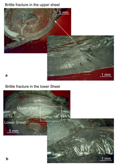
Figure 28. Fracture surfaces characterized by brittle failure [77]: (a) upper sheet and (b) lower sheet.
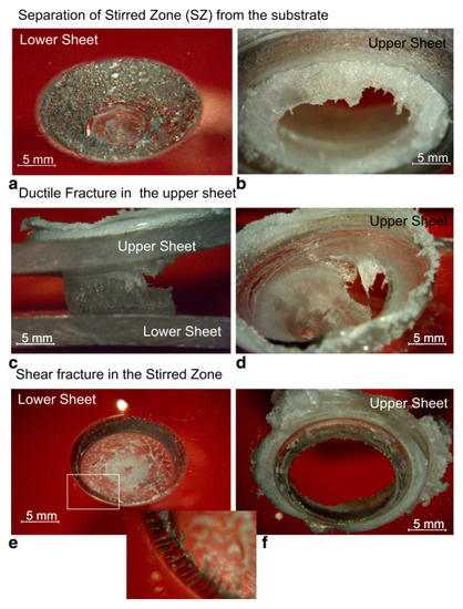
Figure 29. Typical failure modes of friction stir spot welds [77]. Separation of the SZ from the substrate in (a) lower sheet and (b) upper sheet. Ductile fracture in the upper sheet (c) side view and (d) upper view. (e, f) shear fracture in the stirred zone.
The occurrence of one or another failure mode, is due to different physical phenomena, as well as the morphology and geometrical aspects. The formation of voids and porous interlayer between the stirred region and the base materials is often caused by Mode M3 or M4 failures. In addition, the presence of such defects within the stirred region may drive to shear failure (M5). However, geometrical aspects also play a great influence.
Lambiase et al. [74] analyzed the characteristic load-bearing areas of friction spot stir welds, to better understand the influence of the optimal plunging depth. In failure modes M3 and M4, the stirred region behaves as an almost rigid body that progressively separates from the lower and upper sheets, respectively. The fracture originates at the boundary of the stirred region and propagates along the border with the base material. Thus, welds characterized by a large interface area between the stirred region and the upper sheet Aup (depicted in Figure 26c) and a low value of the interface area between the SR and the bottom sheet Alow (depicted in Figure 26d) are prone to fail by separation with the bottom sheet. Similarly, welds characterized by a small area Aweld (shown in Figure 26b) are generally failed by shear failure (M5). The quality of FSS welds and particularly the mechanical behavior depends on the material stirring quality as well as the presence of process induces defects. These defects can be thus classified in:
- Geometrical: incorrect choice of the plunging depth and/or tool dimension, the shape of the tool probe;
- Morphological: formation of porosities, cavities. These depend on the selection of process parameters such as processing speed, length of the dwell time, waiting time, load/displacement control, etc.
- Residual stress: thermal shrinkage leading to residual stress and formation of voids and cavities.
Effect of Process Parameters
The morphology of the welds is determined by several process parameters, which can be classified into processing speeds, phases length, and geometrical aspects, as summarized in Figure 30, and Table 5.
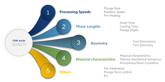
Figure 30. Factors influencing the quality of the welds.
Table 5. Classification of process parameters for FSSW.
|
Category |
Process Parameter |
Brief Description |
References |
|
Processing Speeds |
Plunge Rate |
Speed of the tool during the plunging phase upon reaching the penetration depth |
[49,75,78–80] |
|
Rotation speed |
Speed of the tool during the plunging and dwell phases |
[49,79,81–83] |
|
|
Phases Length |
Pre-heating time |
Period of material pre-heating by slight plunging of the tool over the upper sheet |
[49,79,81–83] |
|
Dwell time |
time elapsing since the tool has reached the final penetration depth and start of cooling. During this period, the tool plunge is stopped while the tool continues to rotate |
[49,75,78,80,82] |
|
|
Cooling time |
Period during which the tool is fully stopped (no plunging and rotation take place) |
[49,81–83] |
|
|
Geometry |
Plunge depth |
Axial displacement of the tool since the first contact with the upper sheet to the final position. This should be greater than the upper sheet thickness and lower than the sum of the sheet thicknesses |
[74,76,77] |
|
Tool shoulder diameter |
− |
[74,76,77] |
|
|
Tool probe diameter |
− |
[76,77,84] |
|
|
Tool probe geometry |
− |
[76,77,84–86] |
|
|
Others |
Plunge force |
Force applied during the dwell phase when load-control is involved in the process |
[74] |
Before treating in detail the influence of the process parameters on the quality, morphology and mechanical behavior of friction spot stir welds, it must be noted that in some cases, there is not a full agreement among the results from different researches. This can be due by several causes, including adoption of different processing windows, materials, analysis methods, as well as depth of analysis. In addition, a further cause of misalignment concerning the influence of a given process parameter on the strength (especially for FSSW of polymers) is also represented by the relatively limited number of papers that have dealt with that process parameter. This makes it even more difficult to generalize the achievements of a certain paper outside the processing window analyzed in that paper.
Figure 31 compares the ranges analyzed in different references for the plunging rate, tool rotation speed and dwell time. Obviously, a direct comparison would be inappropriate as different equipment’s (e.g., tool dimensions, machine capabilities, etc.), and materials are involved in these works. Nevertheless, a graphical representation of these ranges may provide qualitative insights into the processing windows studied. Figure 31a indicates a general consistency among the ranges studied for the plunging rate, the most studied plunge rate ranged between 20 and 40 mm/min. On the other hand, two separate windows can be identified, as shown in Figure 31b, pertaining to low (up to 500–2000 RPM) and high tool rotation speeds (2000–5500 RPM). Finally, three ranges for the dwell time were identified, as shown in Figure 31c: short (up to 20 s), medium (from 20 to 60 s) and long (up to 150 s) dwell time. It is worth noting that the papers involving high ranges of tool rotation speed [69,72,78], also involved short dwell time. This is not coincidental. Indeed, the frictional power is proportional to the tool rotation speed. Therefore, high tool rotation speed involves higher amount of frictional heat and consequently it demands lower dwell time to achieve the joints formation. Nevertheless, the adoption of low or high tool rotation speeds, which come with different power levels, may induce significant differences in temperature distributions. Since the low thermal diffusivity of polymers, the adoption of processing conditions involving high power are expected to produce steeper temperature gradients as those produced by processing conditions involving lower power amounts.
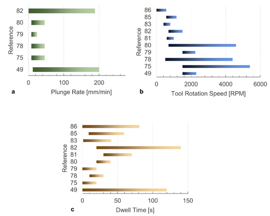
Figure 31. Processing windows analyzed in different papers concerning FSSW of polymers. Effect of (a) plunge rate; (b) tool rotation speed and (c) dwell time.
Plunge Rate
The results reported by Yan et al. [49], indicated the existence of an optimal value of the plunge rate. The authors asserted that extremely low values of this parameter may affect the strength of the welds. This was addressed to defect formation, water absorption, molecular weight reduction, or residual stress generation. On the other hand, as reported by Lambiase et al. [78], extremely high values of the plunge rate may be also detrimental. The adoption of low values of the plunge rate involves short interaction time, lower weld dimensions and worse stirring homogenization and material heating that resulted in lower load-bearing. This can be observed by comparing Figure 32a,b.
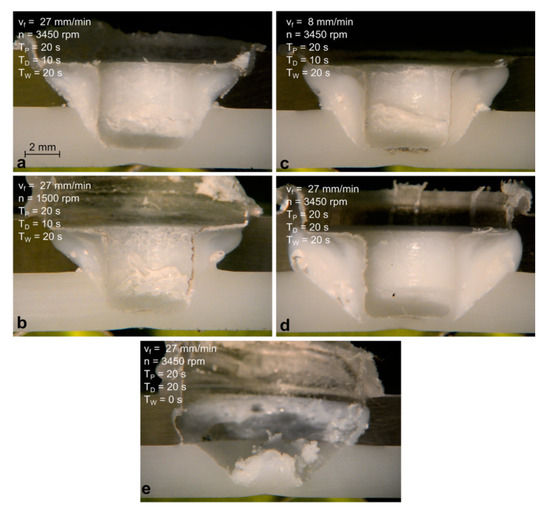
Figure 32. Influence of process parameters on welds morphology [78]. (a) reference condition; (b) reduction of tool rotation speed; (c) reduction of plunging speed; (d) increase of dwell time and (e) reduction of the waiting time.
Rotation Speed
The influence of the tool rotation speed (commonly indicated with or n) has been investigated in several studies. The results do not fully agree about the effect of this process parameter. The results reported in [78,81] indicated a minor influence of n; on the other hand, other studies [82] determined the existence of an optimal value of the tool rotation speed that maximized the strength of the welds. Other studies determined a decreasing strength of the welds with the tool rotation speed [49]. It must be noted that the frictional heat produced by the tool is proportional to the tool rotation speed. Thus, higher values of n involve higher heating. However, because of the strong sensitivity of the mechanical behavior of the polymers by the temperature (especially close to the glass transition temperature), a non-linear relationship between the frictional heat and the tool rotation speed exists. Indeed, as the material is heated over the Tg, the flow stress and the Young modulus drop. This comes with a steep reduction of the contact pressure and consequently the frictional heat. Thus, the difference among the abovementioned studies can be addressed to multiple reasons, including:
- The adoption of different ranges;
- The adoption of different tool dimensions;
- The investigation of different materials, which are characterized by different Tg and softening/melting points;
- The temperature reached during the process.
Pre-Heating Time
The results reported in [75,78,80] indicated that this parameter has negligible effect on the quality of the joints. The studies indicated that, the addition of the pre-heating phase while joining polymers provides a local heating of the material. Only the material underlying the tool probe is heated, while no significant effect develops in the surrounding regions. This was due to the poor thermal diffusivity of polymers. Consequently, the dimension of the welds is not modified as well as the strength.
Dwell Time
This parameter contributes to determining the amount of frictional heat supplied to the weld when the plunging depth is reached. During this phase, the heat enlarges the weld dimension. Thus, longer dwell time involve larger welds and consequently, higher load-bearing, as can be observed by comparing Figure 32a,d reported in [78]. However, extremely high values of dwell time may come with detrimental effects. Indeed, as reported in [49], the adoption of extremely long dwell time may affect the strength of the welds. This was addressed to additional material extrusion and the generation of a cavity as well as molecular weight decrease due to mechanical scission of molecular chains.
Cooling Time
At the end of the dwell phase, the material of the stirred region is under a rubber or pasty state. Thus, sufficient cooling time is required to prevent the tear of the SR by means of the tooltip, as shown in Figure 32e and Figure 33. Because of the poor thermal diffusivity of the polymers, the cooling of the stirred region requires a certain time. This depends on the peak temperature reached during the process, the dimension of the stirred region, as well as the thermal properties of the materials involved (the glass transition temperature). During this phase, the tool exerts a double function. Indeed, it applies a certain pressure on the contact surfaces with the stirred region. In addition, it drains heat from the weld enabling a faster cooling. The above considerations would drive towards a temperature-based trigger for tool retraction. As soon as the temperature drops under a given temperature (depending on the thermal characteristic of the polymer), the tool can be immediately retracted. This would involve obvious advantages in terms of process efficiency and productivity. However, this is hindered by the difficulty to measure the temperature of the stirred region during the process.
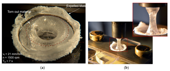
Figure 33. (a) Tearing out effect [75] and (b) material attached to the tool owing to highly insufficient waiting time [76].
Plunge Depth
The plunge depth directly affects the geometry and dimension of the characteristic regions of welds made by FSSW. Increasing the penetration depth (s), the area Aup (and Lup) decreases while the welds area Aweld and Alow increase, as shown in Figure 25. As expected, low penetration depth involved low strength as the weld area was very restricted. On the other hand, extremely high values of the tool plunge depth involved a significant reduction of the Aup, which led to the separation of the SR from the upper sheet. This condition also led to extremely low values of the ultimate shear force, as shown in Figure 34. The highest shear force found under intermediate values of the penetration depth.
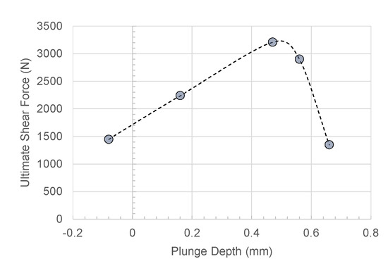
Figure 34. Influence of the penetration depth on the ultimate shear force (data from [77]).
Tool Shoulder and Probe Diameter
The results reported in [77] indicated that, the Ultimate Tensile Stress UTS of the welds increased when larger tool shoulder diameters were adopted and decreased with the tool probe diameter. This was due to the dimension of the stirred region and the characteristic areas. An increase of the tool shoulder diameter D comes with larger values of all the characteristic areas, Aup, Alow, and Aweld. On the other hand, the dimension of the tool probe affected these areas and induced the reduction of the UTS of the welds. The selection of the proper processing conditions enabled to achieve a joint strength of 88% in the case of polycarbonate.
Geometry of the Tool Probe
Being a thermo-mechanical process based on the stirring of the two materials, the geometry of the tool probe strongly influences the strength of the welds. Bilici and Yükler [86] firstly investigated the influence of the tool pin on the mechanical behavior of FSS welds. The authors compared six different geometries, namely: cylindrical (SC), tapered cylindrical (TC), threaded cylindrical (TH), square (SQ), triangular (TR) and hexagonal (HG).
The results reported in Figure 35 indicated that, the adoption of a threaded cylindrical probe enabled an increase of the ultimate shear force by 28% as compared to the welds made by a straight cylindrical shape, using the identical process parameters. This was addressed to a better material flow. The probe profile is also responsible of the weld nugget geometry and dimension after the tool retraction from the welds. Thus, this portion of the material does not provide any load-bearing capability. This idea drove further analysis concerning more exotic probe shapes. Yan et al. [85] investigated the adoption of a triflute tool probe to reduce the dimension of the weld nugget and reduce the amount of material ejected from the weld. This tool enabled significant increase in the welds force as the larger welds area. The authors also performed an experimental work concerning a double pin tool, which also enabled higher strength of the welds. The schematics of these probes are depicted in Figure 36.
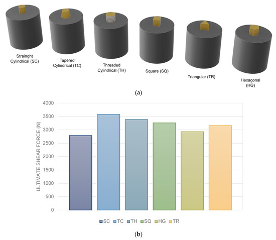
Figure 35. Influence of the tool probe shape on the mechanical behavior of the welds (data extracted from [86]). (a) pin shapes and (b) effect of pin shape on the UTS of the joint.
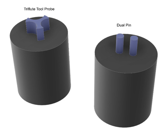
Figure 36. Schematic of triflute and dual pin used for FSSW of polymers.
Effect of Plunging Force
Most of the papers concerning friction spot stir welding of polymers involved a displacement control during the entire welding process. This was due to a much simpler configuration of the machines adopted. However, this also involved the formation of a porous region surrounding the stirred zone. This region was characterized by the presence of large bubbles owing to moisture absorbed by the polymer, air trapped during the process as well as thermal shrinkage during the cooling phase. The presence of these bubbles dramatically affected the mechanical behavior of the welds as they reduced the load-bearing are and acted as stress raisers. The sequence of the material flow during friction spot stir welding of transparent polycarbonate is reported in Figure 37a–f, as reported in [74]. Here, the formation of the bubbles between the stirred and surrounding regions is observed at the beginning of the dwell phase. During the plunging phase, the axial load exerts compressive stress that hinders the bubble formation. However, as the tool motion is stopped, the axial load drops leading to the easier formation of the bubbles.
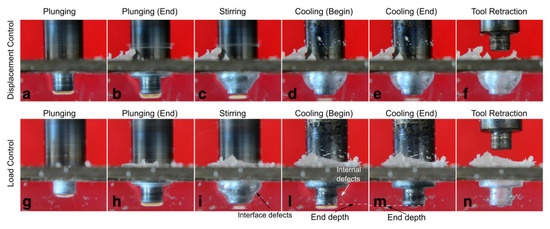
Figure 37. Effect of load control during cooling phase [74]. Sequence of processing phases under (a–e) displacement control and (g–n) load control.
To overcome the presence of this porous region, Lambiase et al. [74] involved load control during the cooling phase, as shown in Figure 37g–n. This acted as compressive stress that enabled the closure of the porosities and cavities formed at the beginning of the dwell phase. The results reported by the authors were extremely promising; indeed, the welds made under load control reached a joint efficiency of 99%.
References
- Lambiase, F.; Ko, D.-C. Feasibility of mechanical clinching for joining aluminum AA6082-T6 and Carbon Fiber Reinforced Polymer sheets. Mater. Des. 2016, 107, 341–352.
- Katayama, S. Handbook of laser welding technologies. Woodhead Publishing: Cambridge, UK, 2013.
- Troughton, M. Handbook of Plastics Joining: A Practical Guide. . William Andrew: Norwich, NY, USA, 2008; p 600.
- Camanho, P.P.; Tong, L. Composite joints and connections. Principles, modelling and testing. 80 High Street, Sawston, Cambridge CB22 3HJ, UK, 2011; p 544.
- Kiss, Z.; Czigány, T. Applicability of friction stir welding in polymeric materials. Period. Polytech. Mech. Eng. 2007, 51(1), 15.
- Eslami, S.; Tavares, P.J.; Moreira, P.M.G.P. Friction stir welding tooling for polymers: review and prospects. Int. J. Adv. Manuf. Technol. 2016, 89, 1677–1690.
- Kumar, R.; Singh, R.; Ahuja, I.P.S.; Penna, R.; Feo, L. Weldability of thermoplastic materials for friction stir welding- A state of art review and future applications. Compos. Part B: Eng. 2018, 137, 1–15.
- Lambiase, F.; Ko, D.C. Two-steps clinching of aluminum and Carbon Fiber Reinforced Polymer sheets. Compos. Struct. 2017, 164, 180–188.
- Lambiase, F.; Paoletti, A.; Di Ilio, A. In Advances in Mechanical Clinching: Employment of a Rotating Tool, Procedia Engineering, 2017; pp 200–205.
- Lambiase, F.; Paoletti, A. Friction-assisted clinching of Aluminum and CFRP sheets. J. Manuf. Process. 2018, 31, 812–822.
- Lee, C.-J.; Shen, G.; Kim, B.-M.; Lambiase, F.; Ko, D.-C. Analysis of Failure-Mode Dependent Joint Strength in Hole Clinching from the Aspects of Geometrical Interlocking Parameters. Metals 2018, 8, 1020–1031.
- Derazkola, H.A.; Elyasi, M. The influence of process parameters in friction stir welding of Al-Mg alloy and polycarbonate. J. Manuf. Process. 2018, 35, 88–98.
- Derazkola, H.A.; Khodabakhshi, F.; Simchi, A. Friction-stir lap-joining of aluminium-magnesium/poly-methyl-methacrylate hybrid structures: thermo-mechanical modelling and experimental feasibility study. Sci. Technol. Weld. Join. 2018, 23, 35–49.
- Lambiase, F.; Paoletti, A.; Di Ilio, A. Forces and temperature variation during friction stir welding of aluminum alloy AA6082-T6. Int. J. Adv. Manuf. Technol. 2018, 99, 337–346.
- Lambiase, F.; Paoletti, A.; Grossi, V.; Di Ilio, A. Analysis of loads, temperatures and welds morphology in FSW of polycarbonate. J. Mater. Process. Technol. 2019, 266, 639–650.
- Derazkola, H.A.; Simchi, A. An investigation on the dissimilar friction stir welding of T-joints between AA5754 aluminum alloy and poly(methyl methacrylate). Thin-Walled Struct. 2019, 135, 376–384.
- Nandan, R.; DebRoy, T.; Bhadeshia, H.K.D.H. Recent advances in friction-stir welding–Process, weldment structure and properties. Prog. Mater. Sci. 2008, 53, 980–1023.
- Simar, A.; Bréchet, Y.; de Meester, B.; Denquin, A.; Gallais, C.; Pardoen, T. Integrated modeling of friction stir welding of 6xxx series Al alloys: Process, microstructure and properties. Prog. Mater. Sci. 2012, 57, 95–183.
- He, X.; Gu, F.; Ball, A. A review of numerical analysis of friction stir welding. Prog. Mater. Sci. 2014, 65, 1–66.
- Derazkola, H.A.; Khodabakhshi, F. A novel fed friction-stir (FFS) technology for nanocomposite joining. Sci. Technol. Weld. Join. 2020, 25, 89–100.
- Elyasi, M.; Aghajani Derazkola, H.; Hosseinzadeh, M. Investigations of tool tilt angle on properties friction stir welding of A441 AISI to AA1100 aluminium. Proc. Inst. Mech. Eng. Part B: J. Eng. Manuf. 2016, 230, 1234–1241.
- Derazkola, H.A.; Aval, H.J.; Elyasi, M. Analysis of process parameters effects on dissimilar friction stir welding of AA1100 and A441 AISI steel. Sci. Technol. Weld. Join. 2015, 20, 553–562.
- Derazkola, H.A.; F.R., K.; Khodabakhshi, F. Effects of processing parameters on the characteristics of dissimilar friction-stir-welded joints between AA5058 aluminum alloy and PMMA polymer. Weld. World 2018, 62, 117–130.
- Huang, Y.; Meng, X.; Xie, Y.; Wan, L.; Lv, Z.; Cao, J.; Feng, J. Friction stir welding/processing of polymers and polymer matrix composites. Compos. Part A: Appl. Sci. Manuf. 2018, 105, 235–257.
- Elyasi, M.; Derazkola, H.A. Experimental and thermomechanical study on FSW of PMMA polymer T-joint. Int. J. Adv. Manuf. Technol. 2018, 97, 1445–1456.
- Moreno-Moreno, M.; Macea Romero, Y.; Rodríguez Zambrano, H.; Restrepo-Zapata, N.C.; Afonso, C.R.M.; Unfried-Silgado, J. Mechanical and thermal properties of friction-stir welded joints of high density polyethylene using a non-rotational shoulder tool. Int. J. Adv. Manuf. Technol. 2018, 97, 2489–2499.
- Kumar, S.; Roy, B.S. Novel study of joining of acrylonitrile butadiene styrene and polycarbonate plate by using friction stir welding with double-step shoulder. J. Manuf. Process. 2019, 45, 322–330.
- Arici, A.; Sinmazçelýk, T., Effects of double passes of the tool on friction stir welding of polyethylene. J. Mater. Sci. 2005, 40, 3313–3316.
- Mosavvar, A.; Azdast, T.; Moradian, M.; Hasanzadeh, R. Tensile properties of friction stir welding of thermoplastic pipes based on a novel designed mechanism. Weld. World 2019, 63, 691–699.
- ASTM D 638. Standard Test Method for Tensile Properties of Plastics. ASTM: West Conshohocken, PA, USA, 2000.
- Derazkola, H.A.; Simchi, A. Effects of alumina nanoparticles on the microstructure, strength and wear resistance of poly(methyl methacrylate)-based nanocomposites prepared by friction stir processing. J. Mech. Behav. Biomed. Mater. 2018, 79, 246–253.
- Gao, J.; Cui, X.; Liu, C.; Shen, Y. Application and exploration of friction stir welding/processing in plastics industry. Mater. Sci. Technol. 2017, 33, 1145–1158.
- ASTM D2240-Standard Test Method for Rubber Property—Durometer Hardness. ASTM: West Conshohocken, PA, USA, 2000.
- Lambiase, F.; Grossi, V.; Paoletti, A. Advanced mechanical characterization of friction stir welds made on polycarbonate. Int. J. Adv. Manuf. Technol. 2019, 104, 2089–2102.
- Vijendra, B.; Sharma, A. Induction heated tool assisted friction-stir welding (i-FSW): A novel hybrid process for joining of thermoplastics. J. Manuf. Process. 2015, 20, 234–244.
- Nandhini, R.; Moorthy, M. K.; Muthukumaran, S. Effect of Welding Parameters on Microstructure and Tensile Strength of Friction Stir Welded PA 6,6 Joints. Int. Polym. Process. 2017, 32, 416–424.
- Gao, J.; Shen, Y.; Zhang, J.; Xu, H., Submerged friction stir weld of polyethylene sheets. J. Appl. Polym. Sci. 2014, 131, (22).
- Zafar, A.; Awang, M.; Khan, S. R.; Emamian, S. Investigating Friction Stir Welding on Thick Nylon 6 Plates. Weld. Res. 2016, 95, 201–218.
- Saeedy, S.; Givi, M. K. B. Investigation of the effects of critical process parameters of friction stir welding of polyethylene. Proc. Inst. Mech. Eng. Part B: J. Eng. Manuf. 2011, 225, 1305–1310.
- Bozkurt, Y. The optimization of friction stir welding process parameters to achieve maximum tensile strength in polyethylene sheets. Mater. Des. 2012, 35, 440–445.
- Jaiganesh, V.; Maruthu, B.; Gopinath, E. Optimization of Process Parameters on Friction Stir Welding of High Density Polypropylene Plate. Procedia Eng. 2014, 97, 1957–1965.
- Derazkola, H.A.; Simchi, A.; Lambiase, F. Friction stir welding of polycarbonate lap joints: Relationship between processing parameters and mechanical properties. Polym. Test. 2019, 79, 105999.
- Rezaee Hajideh, M.; Farahani, M.; Alavi, S.A.D.; Molla Ramezani, N. Investigation on the effects of tool geometry on the microstructure and the mechanical properties of dissimilar friction stir welded polyethylene and polypropylene sheets. J. Manuf. Process. 2017, 26, 269–279.
- Sahu, S.K.; Mishra, D.; Mahto, R.P.; Sharma, V.M.; Pal, S.K.; Pal, K.; Banerjee, S.; Dash, P. Friction stir welding of polypropylene sheet. Eng. Sci. Technol. Int. J. 2018, 21, 245–254.
- Hoseinlaghab, S.; Mirjavadi, S.S.; Sadeghian, N.; Jalili, I.; Azarbarmas, M.; Besharati Givi, M.K. Influences of welding parameters on the quality and creep properties of friction stir welded polyethylene plates. Mater. Des. 2015, 67, 369–378.
- Eslami, S.; Mourão, L.; Viriato, N.; Tavares, P.J.; Moreira, P.M.G.P. Multi-axis force measurements of polymer friction stir welding. J. Mater. Process. Technol. 2018, 256, 51–56.
- Bagheri, A.; Azdast, T.; Doniavi, A. An experimental study on mechanical properties of friction stir welded ABS sheets. Mater. Des. 2013, 43, 402–409.
- Eslami, S.; Ramos, T.; Tavares, P.J.; Moreira, P.M.G.P., Shoulder design developments for FSW lap joints of dissimilar polymers. J. Manuf. Process. 2015, 20, 15–23.
- Yan, Y.; Shen, Y.; Zhang, W.; Guan, W. Effects of friction stir spot welding parameters on morphology and mechanical property of modified cast nylon 6 joints produced by double-pin tool. Int. J. Adv. Manuf. Technol. 2017, 92, 2511–2523.
- Lambiase, F.; Grossi, V.; Paoletti, A. Effect of tilt angle in FSW of polycarbonate sheets in butt configuration. Int. J. Adv. Manuf. Technol. 2020, 106, 2451–2462.
- Aghajani Derazkola, H.; Simchi, A. Experimental and thermomechanical analysis of friction stir welding of poly(methyl methacrylate) sheets. Sci. Technol. Weld. Join. 2018, 23, 209–218.
- Eyvazian, A.; Hamouda, A.M.; Aghajani Derazkola, H.; Elyasi, M. Study on the effects of tool tile angle, offset and plunge depth on friction stir welding of poly(methyl methacrylate) T-joint. Proc. Inst. Mech. Eng. Part B: J. Eng. Manuf. 2019, 0954405419889180.
- Kiss, Z.; Czigány, T. Effect of welding parameters on the heat affected zone and the mechanical properties of friction stir welded poly(ethylene-terephthalate-glycol). J. Appl. Polym. Sci. 2012, 125, 2231–2238.
- Ülker, A.; Sayer, S.; Ceyhun, V. Welding parameters and joint strength optimization during friction stir welding of high density polyethylene (HDPE) using the Taguchi method. Mater. Test. 2016, 58, 423–432.
- Arici, A.; Selale, S. Effects of tool tilt angle on tensile strength and fracture locations of friction stir welding of polyethylene. Sci. Technol. Weld. Join. 2007, 12, 536–539.
- Lambiase, F.; Grossi, V.; Di Ilio, A.; Paoletti, A. Feasibility of friction stir joining of polycarbonate to CFRP with thermosetting matrix. Int. J. Adv. Manuf. Technol. 2020, 106, 2451–2462.
- Sadeghian, N.; Besharati Givi, M.K., Experimental optimization of the mechanical properties of friction stir welded Acrylonitrile Butadiene Styrene sheets. Mater. Des. 2015, 67, 145–153.
- Panneerselvam, K.; Lenin, K. Joining of Nylon 6 plate by friction stir welding process using threaded pin profile. Mater. Des. 2014, 53, 302–307.
- Gao, J.; Shen, Y.; Xu, H. Investigations for the mechanical, macro-, and microstructural analyses of dissimilar submerged friction stir welding of acrylonitrile butadiene styrene and polycarbonate sheets. Proc. Inst. Mech. Eng. Part B: J. Eng. Manuf. 2015, 230, 1213–1220.
- Yan, Y.; Shen, Y.; Lan, B.; Gao, J. Influences of friction stir welding parameters on morphology and tensile strength of high density polyethylene lap joints produced by double-pin tool. J. Manuf. Process. 2017, 28, 33–40.
- Trimble, D.; Monaghan, J.; O’Donnell, G.E. Force generation during friction stir welding of AA2024-T3. Cirp Ann. -Manuf. Technol. 2012, 61, 9–12.
- Mendes, N.; Neto, P.; Simão, M.A.; Loureiro, A.; Pires, J.N. A novel friction stir welding robotic platform: welding polymeric materials. Int. J. Adv. Manuf. Technol. 2016, 85, 37–46.
- Eslami, S.; Francisco Miranda, J.; Mourão, L.; Tavares, P.J.; Moreira, P.M.G.P. Polyethylene friction stir welding parameter optimization and temperature characterization. Int. J. Adv. Manuf. Technol. 2018, 99, 127–136.
- Simões, F.; Rodrigues, D.M., Material flow and thermo-mechanical conditions during Friction Stir Welding of polymers: Literature review, experimental results and empirical analysis. Mater. Des. 2014, 59, 344–351.
- Nandhini, R.; Moorthy, M.K.; Muthukumaran, S.; Kumaran, S. Influence of process variables on the characteristics of friction-stir-welded polyamide 6,6 joints. Mater. Und Werkst. 2019, 50, 1139–1148.
- Pirizadeh, M.; Azdast, T.; Rash Ahmadi, S.; Mamaghani Shishavan, S.; Bagheri, A. Friction stir welding of thermoplastics using a newly designed tool. Materials & Design (1980–2015) 2014, 54, 342–347.
- Azarsa, E.; Mostafapour, A. Experimental investigation on flexural behavior of friction stir welded high density polyethylene sheets. J. Manuf. Process. 2014, 16, 149–155.
- Eslami, S.; de Figueiredo, M.A.V.; Tavares, P.J.; Moreira, P.M.G.P. Parameter optimisation of friction stir welded dissimilar polymers joints. Int. J. Adv. Manuf. Technol. 2018, 94, 1759–1770.
- Moochani, A.; Omidvar, H.; Ghaffarian, S.R.; Goushegir, S.M. Friction stir welding of thermoplastics with a new heat-assisted tool design: mechanical properties and microstructure. Weld. World 2019, 63, 181–190.
- Nath, R.K.; Maji, P.; Barma, J.D., Development of a Self-Heated Friction Stir Welding tool for welding of polypropylene sheets. J. Braz. Soc. Mech. Sci. Eng. 2019, 41, 553.
- Derazkola, H.A.; Eyvazian, A.; Simchi, A. Modeling and experimental validation of material flow during FSW of polycarbonate. Mater. Today Commun. 2020, 22, 100796.
- Derazkola, H.A.; Simchi, A. Experimental and thermomechanical analysis of the effect of tool pin profile on the friction stir welding of poly(methyl methacrylate) sheets. J. Manuf. Process. 2018, 34, 412–423.
- Mohammadi Kuhbanani, H.; Yasemi, H.; Aghajani Derazkola, H. Effects of Tool Tilt Angle and Plunge Depth on Properties of Polycarbonate FSW Joint. J. Mod. Process. Manuf. Prod. 2018, 7, 41–55.
- Lambiase, F.; Paoletti, A.; Di Ilio, A. Friction spot stir welding of polymers: control of plunging force. Int. J. Adv. Manuf. Technol. 2017, 90, 2827–2837.
- Paoletti, A.; Lambiase, F.; Di Ilio, A. Analysis of forces and temperatures in friction spot stir welding of thermoplastic polymers. Int. J. Adv. Manuf. Technol. 2016, 83, 1395–1407.
- Lambiase, F.; Paoletti, A.; Di Ilio, A. Effect of tool geometry on loads developing in friction stir spot welds of polycarbonate sheets. Int. J. Adv. Manuf. Technol. 2016, 87, 2293–2303.
- Lambiase, F.; Paoletti, A.; Di Ilio, A. Effect of tool geometry on mechanical behavior of friction stir spot welds of polycarbonate sheets. Int. J. Adv. Manuf. Technol. 2017, 88, 3005–3016.
- Lambiase, F.; Paoletti, A.; Di Ilio, A. Mechanical behaviour of friction stir spot welds of polycarbonate sheets. Int. J. Adv. Manuf. Technol. 2015, 80, 301–314.
- Dashatan, S.H.; Azdast, T.; Ahmadi, S.R.; Bagheri, A. Friction stir spot welding of dissimilar polymethyl methacrylate and acrylonitrile butadiene styrene sheets. Mater. Des. 2013, 45, 135–141.
- Paoletti, A.; Lambiase, F.; Di Ilio, A. Optimization of Friction Stir Welding of Thermoplastics. Procedia CIRP 2015, 33, 563–568.
- Bilici, M.K. Application of Taguchi approach to optimize friction stir spot welding parameters of polypropylene. Mater. Des. 2012, 35, 113119.
- Memduh, K., Friction stir spot welding parameters for polypropylene sheets. Sci. Res. Essays 2012, 7, 947–956.
- Bilici, M.K.; Yükler, A.İ.; Kurtulmuş, M. The optimization of welding parameters for friction stir spot welding of high density polyethylene sheets. Mater. Des. 2011, 32, 4074–4079.
- Yan, Y.; Shen, Y.; Hou, W.; Li, J. Friction stir spot welding thin acrylonitrile butadiene styrene sheets using pinless tool. Int. J. Adv. Manuf. Technol. 2018, 97, 2749–2755.
- Yan, Y.; Shen, Y.; Zhang, W.; Hou, W. Friction stir spot welding ABS using triflute-pin tool: Effect of process parameters on joint morphology, dimension and mechanical property. J. Manuf. Process. 2018, 32, 269–279.
- Bilici, M.K.; Yükler, A.İ. Influence of tool geometry and process parameters on macrostructure and static strength in friction stir spot welded polyethylene sheets. Mater. Des. 2012, 33, 145–152.
This entry is adapted from the peer-reviewed paper 10.3390/ma13102291