Your browser does not fully support modern features. Please upgrade for a smoother experience.
Please note this is an old version of this entry, which may differ significantly from the current revision.
Subjects:
Others
Displacive stress and strain induced transformations are those transformations that occur when the formation of martensite or bainitic ferrite is promoted by the application of stress or strain. These transformations have been shown to be one of the mechanisms by which the mechanical properties of a microstructure can be improved, as they lead to a better ductility and strength by the transformation induced plasticity effect.
- stress induced transformations
- strain induced transformations
- transformation induced plasticity
- displacive transformations
- bainite
- martensite
1. Introduction
Displacive stress induced transformations (SIT) and strain/deformation induced transformations (DIT) include the transformations from austenite (γ), which has a face-centered cubic (fcc) structure, to either martensite or bainitic ferrite, promoted by the application of elastic stress or plastic strain, respectively [1,2,3,4]. This type of transformations can happen from the austenite in microstructures in which the austenite is the only phase [5,6,7,8,9,10,11], which are called fully austenitic microstructures, from now on. They can also occur from the retained austenite in microstructures which consist of different phases [1,4,12,13,14,15,16,17,18,19], which are named multiphase microstructures, from now on. Some examples of multiphase microstructures are microstructures consisting of allotriomorphic ferrite, martensite, bainitic ferrite, and retained austenite [20], bainitic microstructures with retained austenite [21] or microstructures obtained by a quenching and partitioning (Q&P) treatment with retained austenite [22]. The SIT/DIT can happen while a microstructure is subjected to a mechanical test or in a thermomechanical treatment by which a certain final microstructure is aimed.
With respect to the first scenario (SIT/DIT in mechanical tests), the former research on displacive SIT and DIT has mainly focused on the martensite transformation induced plasticity (TRIP) effect at room temperature, which can happen in austenitic or in multiphase microstructures. The TRIP effect refers to the effect by which a SIT/DIT may lead to improved mechanical properties, as these transformations are associated to an increase of volume, i.e., an increase of elongation and an increase of the dislocation density. However, the optimization of the mechanical properties by TRIP effect is not straightforward. The effect of the stress or strain induced martensite on the mechanical properties can vary depending on several factors, such as the thermal or mechanical austenite stability [23,24] and the product phase [25]. In addition, the complexity of the initial microstructure can also have other effects on these transformations, such as the effect of the matrix in multiphase steels [26,27,28]. Oppositely to the wide knowledge about martensite TRIP effect, the bainite TRIP effect has not been so studied. Although this transformation has been detected in multiphase steels deformed above room temperature [2,3,4,19,29], its effect on the mechanical properties and its differences with respect to the martensite TRIP effect have not been assessed yet.
Concerning the second case (SIT/DIT happening in thermomechanical treatments), there are many scenarios that have not received much attention, especially the ones involving the formation of bainite. For instance, although the bainite SIT/DIT has been studied under constant stress [30,31,32,33,34], the formation of bainite while straining fully austenitized steels [35,36] has not been deeply assessed.
2. Metastable Phases Formed by Stress and Strain Induced Transformations
As mentioned, the product of SIT and DIT include martensite and bainitic ferrite. The structure of the bainitic ferrite (αB) is always either body-centered cubic (bcc) or body centered tetragonal (bct) and it has morphology of plate or lath. Depending on the chemical composition of the steel, a bainitic microstructure can contain cementite, martensite, and/or retained austenite, apart from αB. Figure 1a,b show two micrographs showing the granular bainite and plate-like bainite microstructures that were formed in a medium carbon high silicon steel by a DIT at 520 °C and 400 °C, respectively [35].
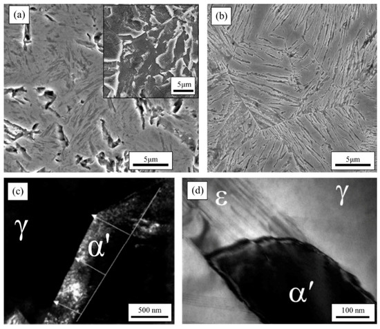
Figure 1. (a) Strain induced (granular) bainite formed at 520 °C in a medium carbon high silicon steel surrounded by a martensite matrix, reprinted from [35], Copyright (2021) with permission from Elsevier; (b) strain induced (plate-like) bainite formed at 400 °C in the same medium carbon high silicon steel surrounded by a martensite matrix, after [35]; (c) In-situ TEM micrograph taken during traction test showing the direct γ →α′ transformation observed while straining a 304 stainless steel at −32 °C, where the white arrows point the interface front and the straight white line is the invariant line; reprinted from [37], Copyright (2021) with permission from Elsevier; (d) in-situ TEM micrograph taken during traction test showing a α′ embryo on a band of ε in a 304L steel deformed at −196 °C, reprinted from [38], Copyright (2021) with permission from Taylor & Francis.
However, the structure of martensite is not always the same. In many cases, two different types of martensite are detected: α′-martensite and ε-martensite. The former one is the most common type of martensite, with a bcc or bct structure and whose nucleation is associated with dislocation pile-ups on the active slip plane of γ [39]. On the other hand, ε-martensite, which has a hexagonal close-packed (hcp) structure, is less common. ε-martensite has been mainly studied in high manganese steels or in austenitic steels (>12 wt. %) [39,40,41,42,43,44,45,46], although it has also been observed in a low fraction in low-alloy steels [47]. Its nucleation occurs from randomly spaced overlapping γ stacking faults formed at grain boundaries [39] and, in many occasions, it is an intermediate phase during the α′-martensite, i.e., the martensitic transformation follows the sequence γ→ ε →α′ [48]. Whereas Figure 1c is an example of a direct γ →α′ transformation observed while straining a 304 stainless steel at −32 °C, Figure 1d is an example of a γ→ ε →α′ transformation in a 304L steel deformed at −196 °C, as in the micrograph one can see a α′ embryo on a band of ε. In multiphase structures, the transformation process is usually γ →α′, where the transformation γ→ ε is only sporadically reported [47].
The appearance of the metastable phases named in this section as a product of SIT/DIT mainly depends on the chemical composition of the steel and on the deformation temperature. Hence, whereas the formation of stress or strain induced α′ is very common in many different microstructures [23,25,35,49,50,51,52,53,54,55,56], ε is mainly found in austenitic steels [23,25,39,48,52], although it has been sporadically detected in multiphase steels [47]. The formation of αB has not been reported, to the authors’ knowledge, at room temperature, although it has been found in fully austenitized steels [35] and in multiphase steels [1,3,57] deformed at high temperatures.
3. Resultant Microstructures of Stress and Strain Induced Transformations and Their Strain Hardening Capacity
In this section, the characteristics of α′/ε/αB SIT and DIT are described. These transformations can be obtained by different routes that are detailed next. The most common scenarios are shown in Figure 4. Note that the deformation temperatures could be reached in Figure 4b,c by heating, instead of cooling, depending on the chemical composition of the steel and on whether an initial fully austenitic or multiphase microstructure is aimed. In those cases, the microstructure may need a previous austenitization or a previous heat-treatment, respectively. The characteristics of the SIT/DIT taking place during the mentioned treatments would only be expected to vary significantly depending on the initial structure and not on how the initial structure was obtained.
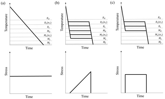
Figure 4. Diagrams showing the possible scenarios to obtain stress induced martensite or bainitic ferrite, where (a) represents a continuous cooling under a constant load; (b) represents a treatment where a deformation is applied at a fixed temperature and (c) represents a pure isothermal treatment under a constant load. The dashed lines show critical temperatures. Units are arbitrary.
3.1. Stress or Strain Induced Martensite Transformations
3.1.1. Continuous Cooling Treatments under Constant Stress
One of the most studied treatments during which martensite is induced is the continuous cooling treatment under constant stress σ, see Figure 4a. Usually, the initial structure is fully austenitic, either because the steel of study is austenitic or because it has been previously austenitized (high temperature deformation). In this case, if the cooling rate was high enough to avoid ferritic/pearlitic/bainitic transformations, a martensite transformation would happen [49,92,100]. The transformation would be athermal, it would start at a temperature Ms(σ) [49,92,100], where Ms(σ) would be higher than Ms if the deformation mode was uniaxial tension, uniaxial compression or torsion [49,92,100,101,102,103]. In addition, in cases in which the Mα′f temperature was above room temperature, the α′ volume fraction would increase under stress, because of the additional mechanical driving force and (if the applied stress was above the austenite σY) the increase in nucleation sites [49]. In cases in which no plastic deformation was introduced, the addition of the mechanical driving force would not only affect the start of the α′ transformation, but also the selection of specific crystallographic variants [84,104,105,106], especially during the first stages of the transformation [106]. The selected variants would have the highest total driving force in absolute value, as ΔGmech is a function of the position of the habit plane [84,104,105]. Variant selection in α′ has also been reported in transformations on continuous cooling under stresses higher than the σY by Liu et al. and it has been associated to the application of stress rather than to the introduction of dislocations [49]. This assumption would follow the same line of thought of Tamura, who suggested that the strain-induced transformations can be understood only in terms of the applied stress [50,107] or of Chatterjee and Bhadeshia, who reached the same conclusion later [69]. Regarding the martensite scale, Liu et al. reported that, the α′ microstructure obtained by applying 70 MPa to an austenitized medium carbon steel during continuous cooling was more refined than the stress-free α′ microstructure obtained by a continuous cooling. They attributed this refinement to the small applied plastic deformation (<5%), which led to the recrystallization of some prior austenite grains at high temperature and to a dislocation density increase in the non-recrystallized grains. The scale of the α′ strain-induced laths/plates has not been reported in any other study, to the authors’ knowledge.
No work in which multiphase structures with retained austenite were cooled under stress have been found by the authors. Although it would be expected that the transformation of the retained austenite would also be promoted at higher temperatures than the ones at which the stress-free martensite transformation would happen, it is important to consider that the retained austenite may also be subjected to hydrostatic stresses that would lead to the stabilization of the retained austenite.
3.1.2. Deformation at a Constant Temperature
Martensite can also be induced when a steel is held at a fixed temperature T—always below Md—while an increasing stress is applied, see Figure 4b. When martensite is induced during straining in austenite structures, it is possible that the transformation process is γ→ ε, γ→ ε →α′, or γ →α′ [25], depending on the applied strain and the deformation temperature [25], where the formation of ε is always preceded by the formation of stacking faults [39]. In addition, the application of stress can also lead to the coalescence of α′ or ε, as previously reported [108,109,110,111].
Regarding variant selection, stress/strain induced α′ [23,50,51,52,112], and ε [23,48,52] present this phenomenon. Even when the transformation happens from a fully austenitic structure, there is no agreement about the reasons of the variant selection phenomenon. While some authors claim that variant selection in transformations from a fully austenitic structure may be explained by the mechanical driving force criterion [48,50,51,52], other authors suggest that some transformation sequences lead to local stress fields which make the analysis more complex [23]. The rules governing variant selection in TRIP transformations in multiphase structures—i.e., formation of stress or strain induced phases from retained austenite—have not been deeply studied. Yamashita et al. studied this phenomenon in a microstructure consisting of ferrite, bainitic ferrite, and retained austenite which was subjected to tensile tests. The retained austenite transformed to α′, always governed by variant selection, although the explanation for this variant selection was not always based on the mechanical driving force, but depended on the location of the retained austenite (at the ferrite grain boundaries or inside the ferrite matrix) [112]. The effect of other types of matrices on the selection of variants of α′ formed by TRIP effect in multiphase microstructures is still unclear.
The mechanical response that is observed when a fully austenitic structure is subjected to tension has been assessed in many austenitic steels. To better understand how a stress–strain curve changes under the influence of the appearance of martensite and why those changes occur, one can use Figure 5, where there are three stress–strain and their corresponding strain hardening rate-strain curves which correspond to three different steels which are fully austenitic before testing. The austenite σY of those three steels are the same at the testing temperature. Note that the steel B seems to yield at a lower stress, although this is only an effect of a stress-induced transformation, as is explained subsequently. Because of the different thermodynamics of the steels, steel A does not undergo any SIT/DIT while being deformed, steel B does undergo a SIT and steel C undergoes a DIT. Using the strain hardening rate-strain curve enables to notice much subtler abnormalities. As can be observed, if the transformation is SIT/DIT (steel B/C), the stress–strain curve takes a sigmoidal curve. After reaching σcrit−SIT and σcrit−DIT, a SIT/DIT starts and the stress–strain behavior is no longer as would expected. From this point onwards, the martensite fraction increases as the stress to which the austenite is subjected is higher [107,113,114], mainly as a function of the strain and not of the temperature [115], until it reaches a limit, see Figure 3. There are several effects that compete when a SIT/DIT takes place during loading and they can be studied by looking at the strain hardening rate–strain curves in Figure 5b. The first of them is called dynamic softening and it is a product of the transformation working as a competing deformation mechanism. It is associated with the fact that the SIT/DIT transformation strain contributes to the total strain, while the stress increases more slowly [116,117] and it usually predominates at low strain values [10]. In some cases, this phenomenon has also been associated to the formation of ε in the early stages [118], as this phase has been proved to be almost ideally plastic [119]. Dynamic softening is characterized by a rapid decrease of the strain hardening rate, as happens for steels B and C in Figure 5b at low strain values. For higher strains, one can observe that the second effect, called static hardening, is predominant. Static hardening is characterized by a strong increase of the strain hardening rate due to the presence of martensite which acts as a reinforcing phase [116,117]. It has been previously reported that, during the static hardening effect, the martensite volume fraction can increase up to a given amount, called percolation threshold [120], and that, up to this point, the austenite stress level is similar to the macroscopic stress [63]. Once the martensite volume fraction is higher than the percolation threshold, the martensite forms a percolating cluster which extends through the whole structure [120]. In this stage, the strain hardening rate further increases until it reaches its maximum value and the austenite stress level deviates from the macroscopic stress level, suggesting that the material is acting as a composite [10,63]. Finally, once the volume fraction of martensite is close to the unity, the material behavior starts to resemble the martensite behavior and, hence, the strain hardening rate starts to decrease [63]. This final hardening has also been attributed to the activation of strain hardening mechanisms which involve a high dislocation density or a complex state of stress, among others [10]. Note that, although all the mentioned effects are predominant at different stages, it could be possible that some of them were not noticeable during the deformation process. These concepts can be extrapolated to the mechanical behavior of a multiphase structure if one understands that the initial microstructure has already a composite-like behavior [26], as would happen for an austenite structure in which α′ has formed by TRIP effect in a high fraction, i.e., after the percolation threshold has been overcome. However, in this case, the retained austenite may be more stable against deformation depending on several factors: (a) its chemical stability, which depends on its chemical composition [121]; (b) in the case that the matrix phase has formed by a displacive transformation, the stability of the retained austenite increases because of the hydrostatic stresses that the matrix exerts on this retained austenite, as reported in Section 3.2.2. [28]; and (c) if the matrix phase is αB, the amount of dislocations introduced during the transformation in the retained austenite mechanically stabilize it [122].
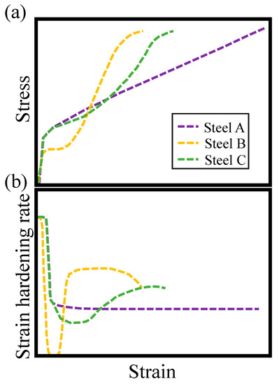
Figure 5. (a) Stress–strain curves and (b) strain hardening rate–strain curves corresponding to three different steels with a fully austenitic structure before the test starts and with the same austenite σY. Steel A is plastically deformed and no stress/strain induced transformation occurs and steels B and C undergo stress and strain transformations, respectively. Units are arbitrary.
Therefore, if one wants to control the mechanical properties of a microstructure which contains retained austenite or that is fully austenitic and that is expected to undergo TRIP effect, one must control several factors. First, as mentioned, the austenite stability is one of the most important factors controlling the mechanical properties of these structures. If the austenite stability is low, a SIT or DIT starts at very low strain values and the material yield strength and elongation are lower, although their ultimate tensile strength is high [23,24,123]. If the austenite is too stable, the TRIP effect may never occur, hence, its benefits cannot be exploited [123]. If the austenite stability is high enough, the ultimate tensile strength of the material is not so high, although its elongation is higher [24]. In addition, it has been reported that, in an austenitic steel with rather stable austenite, the formation of martensite—specially α′, rather than ε—during straining leads to higher uniform elongations [25] because of the suppression or delay of the necking phenomenon [124]. Previous studies have shown that the uniform elongation can be maximized if it is made sure that the induced transformation continues until the latter stage of deformation or the onset of necking [107,115,125] and that the transformation rate is slow, as the dislocations have time to be accommodated and the local stresses can be suppressed [23,115]. The combination of high strength and high ductility can be obtained at temperatures close to Md at which the DIT starts for high strains, before the necking effect takes place, enabling its suppression [24]. A similar effect has been reported in multiphase microstructures [126,127,128].
Second, the strain rate can also affect the mechanical behavior, depending on whether the specimen is deformed under isothermal or under adiabatic conditions, on the product phase and on the deformation temperature. Generally, under isothermal conditions, an increase of the strain rate leads to an increase of the final fraction of stress or strain induced martensite [6,129]. However, if the strain rate is too high, there is a transition from isothermal to adiabatic material behavior, which makes the SFE increase [9,120,129,130] and the driving force for the transformation decrease (in absolute value) [131]. Therefore, using higher strain rates would decrease the volume fraction of stress/strain induced martensite as the strain rate is higher [9,131,132,133,134]. In multiphase microstructures, the effect of the strain rate follows similar trends [135,136,137].
3.2. Stress or Strain Induced Bainite Transformations
The stress or strain induced bainite transformations have not been as studied as the martensite ones. For instance, the authors have not found any work where the effect of a constant stress on the bainite transformation in continuous cooled structures is assessed. However, the effect of a constant uniaxial stress on the αB transformation has been assessed in isothermal treatments, as in Figure 4c. It has been found out that the application of an elastic uniaxial stress accelerates the αB transformation [30,31,32,33,34], provided that the stress is not very low (few MPa) [33], attributed to the increase of driving force (in absolute value). The kinetics of the transformation were also shown to be accelerated when plastic uniaxial deformation was applied during the isothermal holding [31,99,138,139,140] as a result of the increase in nucleation sites (defects) [31]. Regarding the αB volume fraction, although it would be expected to increase if the transformation happened under elastic stress due to the addition of the mechanical driving force, Shipway and Bhadeshia did not report changes for σ < σY in a Fe-0.45C2.08Si-2.69Mn (wt %) steel [32]. If higher stresses are applied, the effect on the volume fraction of αB is not clear, though. Although previous results have shown that the introduction of dislocations prior to the transformation mechanically stabilizes the austenite against either αB or α′ transformation [97,98,141], theoretically, the addition of the mechanical driving force would shift the T0 curve towards higher carbon content values. This would imply that the transformation would not stop until the austenite reached a higher carbon content, which may lead to a higher fraction of αB. Although this fact was not discussed by Freiwillig et al., they showed that, when deformation was applied during an isothermal holding, the final volume fraction of αB decreased with respect to the one obtained by the standard treatment if the steel carbon content was above 0.86 wt %, while it increased with respect to the one obtained by the standard treatment for a steel with carbon content of 0.43 wt % [138]. The application of stress has also been shown to lead to transformation plasticity strains, i.e., anisotropic portion of the transformation strains: the changes in length due to the αB transformation are not the same along all axes [32,33,34,142,143]. This transformation plasticity is due to variant selection effects driven by the same mechanisms that drive the α′ transformations during continuous cooling under constant stresses, i.e., variants which are preferentially promoted by the applied stress (those whose habit plane lies at about 45° with respect to the deformation direction) tend to form first and their fraction tends to be the highest [30,33,34,104,143,144,145]. Variant selection affects the microstructure, which becomes much more organized after transformation under stress, i.e., in each PAG, there are fewer sheaves which are bigger than the ones obtained by stress-free transformation. The reduction of sheaves affects the number of blocks of austenite that are present in the microstructure, i.e., microstructures show less blocky γ if they have been transformed under the effect of stress [145]. To the best knowledge of the authors, the effect of the stress on the thickness of the αB has not been assessed, although it would be expected that microstructures are refined because of the increase of driving force [146,147,148], σY (in the case σY is overcome) [146,147,148], and transformation kinetics [149]. It has been reported, though, that applying stress while a specimen is isothermally treated promoted the coalescence of αB plates [150]. Nevertheless, further research is needed.
Finding studies about αB SIT/DIT happening while straining a fully austenitic structure is not very common, only reported in [35,36] to the authors’ knowledge. In multiphase structures, the αB SIT/DIT at temperatures higher than room temperature have been reported in few studies [2,3,4,19,29], although their effect on the mechanical properties or the differences with respect to the SIT/DIT taking place in fully austenitic structures has not been discussed. Further research would be needed in order to know if the conclusions made with the α′ and ε transformations could be extrapolated to αB transformations, although some differences are expected, such as: (a) while the martensite transformation can be spontaneous, the bainitic transformation is thermally activated, which may inhibit the SIT/DIT in some extent; (b) while martensite transformation does not lead to any carbon partition, carbon is partitioned from αB after a plate/lath is fully grown, which is expected to increase the SFE [151,152] and the driving force for the transformation [149], inhibiting the SIT/DIT in a higher extent as the transformation progresses [153]; (c) bainitic ferrite may not be as hard as martensite because of their different carbon contents, hence, the αB TRIP effect may not lead to such a pronounced strengthening as the α′ TRIP.
This entry is adapted from the peer-reviewed paper 10.3390/met11020299
This entry is offline, you can click here to edit this entry!