Your browser does not fully support modern features. Please upgrade for a smoother experience.
Please note this is an old version of this entry, which may differ significantly from the current revision.
Subjects:
Engineering, Mechanical
In the present world, passive control finds application in various areas like flow over blunt projectiles, missiles, supersonic parallel diffusers (for cruise correction), the engine of jets, static testbeds of rockets, the ports of internal combustion engines, vernier rockets, and single expansion ramp nozzle (SERN) rockets. In this review, various passive control techniques to control the base pressure and regulate the drag force are discussed. In the study, papers ranging from subsonic, sonic, and supersonic flow are discussed. Different types of passive control management techniques like cavity, ribs, dimple, static cylinder, spikes, etc., are discussed in this review article.
- base pressure
- drag
- recirculation zone
- mach number
- passive control
1. Introduction
Turbulent base flows are still an active area of research due to their considerable influence on aerodynamic vehicles’ operation and permanency. Base flows are embodied by a mammoth partition of the shear layer occurring at the base due to a sudden change in the rear geometry. The base region’s divided flow gives rise to two extremely undesirable issues: the base’s instability and an upsurge in the drag. The instability results in erratic loads and pummeling phenomena; the drag force is termed base drag force and, in some specific instances, contributes to as high as 60% of the total drag.
Numerous critical issues impact base flows; a few vital parameters are Mach number, type of boundary layer before the separation, and geometry. Studies were conducted to understand the base flows over an extensive range of flow regimes, subsonic to hypersonic speeds, over the years. Despite these attempts, real insight continues to remain distant. From the previous studies, it is realized that the key factors that influence the dynamics of the flow in the base area are the growth of the shear layer and its reattachment, the recirculation region nearby to the base, shedding of the vortex, and ultimately, the interfaces among them all.
Several studies were reported in the literature involving different characteristics of base flows. Their study outcomes can be categorized into two groups: one that concentrates on the behavior of the flow field in the base’s neighborhood, and the other on individuals exploring the procedures to control the base pressure and hence, reduce the base drag. The vital part of these investigations tries to identify the essential attributes and tools of base flow and its conduct. Limited past assessments are deliberated as follows.
A study carried out by the researchers suggests that the significant pressure at the base resembles a significant recirculation region in the backward-facing step [1]. Investigators from their numerical study on an axisymmetric turbulent boundary layer and reattaching flow argue that large-scale coherent motions at a Strouhal number (defined as St = fD/U) of 0.2 dominate an ordered structure.
Due to the above problem, many researchers tried to control the base pressure; we did not control the skin friction drag due to the mission requirements. While exiting, the nozzle flow gets separated and later reattached at a point in the enlarged duct. The distance from the nozzle exit to the reattachment point is known as the reattachment length. This point on the expanded duct wall is significantly affected by the nozzle pressure ratio, the Mach number, and the area ratio.
Hence, this manuscript reviews some of the latest techniques based on passive control methods to optimize the base pressure and drag. There is an urgent requirement to control this low-pressure in the base region and bring it close to atmospheric pressure to accomplish near zero base drag. The base drag reduction can be achieved by increasing the base pressure by breaking the powerful vortex located in the recirculation zone. There are two ways to regulate the base pressure: (1) active control and (2) passive control.
Dynamic control of base flows is realized through blowing or suction methods and hence needs an external source of energy. This type of control’s main advantage is that it can be switched on and off as needed. However, the main disadvantage of this type of control is the unavailability of such a high source of energy and the extra weight added to aerospace vehicles like rockets, launch vehicles, etc., where the vehicle’s weight plays a key role.
In some cases, it is not feasible to get an additional external source of energy. However, in passive control, the base pressure is controlled by employing the structures’ geometric changes using ribs, cavities, boattails, splitter plates, and locked vortex mechanisms. Unlike active control, passive control does not require an external source of energy; hence, it is neither expensive nor leads to design complexity and is simple to fabricate.
Figure 1 shows the complex flow field of sudden expansion. The boundary layer separation, formation of primary recirculation zone at the base corner, and reattachment location at the wall can be observed. The passive control is used to disturb this flow field, and hence it increases the base pressure and reduces the base drag.
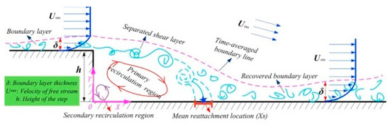
Figure 1. Sudden Expansion Phenomenon [2].
Figure 2 and Figure 3 show the schematic diagram of over-expanded and under-expanded suddenly expanded flow coming out from a convergent-divergent nozzle.
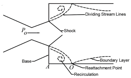
Figure 2. Schematic diagram of over-expanded flow field.
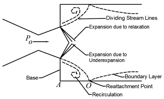
Figure 3. Schematic diagram of the under-expanded flow field.
In the above Figure 4, the flow is coming from an upstream condition (P1 M1 d1) to a downstream state (P2 M2 d2). Pb is the pressure at the base of the duct.
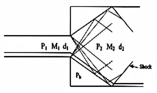
Figure 4. Schematic diagram of internal flow.
Figure 5A shows the external flow over an artillery shell. Here shock waves are formed at the end of the shell, and expansion waves are formed at its base. Here Pb is the pressure at the base of the shell, and P1M1 is the flow conditions. Figure 5B shows the schematic diagram of external flow over a blunt base. Figure 5C shows the schematic diagram of coherent vortex structures.
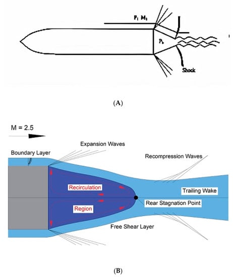
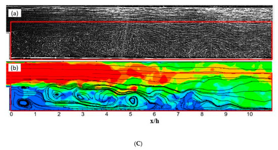
Figure 5. Schematic diagram of external flow. (A) External flow over an artillery shell; (B) Flow over a blunt base; (C) Coherent Vortex structures of in the instantaneous flow (a) Visualization (b) Streamlines with velocity contour [3].
2. Various Types of Passive Controls
Both numerical and experimental studies have been conducted to study the effect of passive control. As passive control is accomplished by geometrical modification, it is more convenient to apply. Whereas in the case of active control, a considerable amount of external energy source is needed, which is challenging to provide. External aerodynamics, such as Ahmed body and boat tailing, as in these external flow types, is very strenuous to give an external energy source. In the case of launch vehicles, missiles, rockets, and aircraft bombs, the passive control mechanism is preferred from the design point of view, ease of fabrication, and the mission’s safety, which is a mandatory requirement.
2.1. Passive Control in the Form of Cavity
A cavity can be in the form of a rectangular shape. The vortices generated due to the flow past the cavity are studied by Ashcroft and Zhang [4]. This study’s main focus is instant development and time mean of turbulent flow structures in the cavity’s shear layer. PIV is conducted at 32 m/s, 37 m/s, and 42 m/s.
The data’s main characteristics are creating the shear layer at a distance downstream of the leading edge and reverse flow at the cavity base. The growth of cavity shear layers was studied by vorticity thickness as a measurement of shear thickness to quantify the time-mean development of shear layers.
Pandey and Rathakrishnan [5] did an experimental study on Mach 1.74 convergent-divergent axisymmetric nozzle sudden spread to circular pipelines with a full transverse area, provided with rectangular cavities. Experimental studies focused on base pressure and the flow field in the extended duct. Depending on the expansion level, the area ratio of the pipe, and the ratio length-to-diameter ratio (L/D) of the enlarged duct, it is found that the base pressure is affected significantly. The cavities increase the base pressure for a lower area ratio. Therefore, for small area ratios, the cavity aspect ratio substantially influences the base pressure.
The duct length in the range from 0 to about 3 plays a significant role in fixing the base pressure level with and without cavities. There is a minimum duct length for the flow to remain attached to the wall. The base pressure for L/D rises steeply from 0 to 3. For L/D more than 3, the base pressure remains almost constant. This shows the minimum extended duct length needed for the flow to stay attached to the duct. It also implies that the effect of increasing oblique shock intensity at the nozzle exit, due to the ample free space available for the flow at the base, is offset by expansion for the area ratio 10 [5].
The isentropic nozzle pressure ratio required for the ideal expansion at the Mach 1.74 nozzle is 5.24. Hence, the nozzle exit flow is over-expanded for the nozzle pressure 2.10 to 3.48 of the present study. Therefore, under these circumstances, an oblique shock wave is positioned at the nozzle exit. After moving through the shock wave in the shear layer, the flow finds ample space at the base to relax. Thus, the base pressure is determined by the combined effect of the oblique shock wave and expansion level.
Due to the change in the expansion level and NPR from 2.10 to 3.48, the shock wave pattern also changes. The results show that the flow to remain attached with the duct wall requires a minimum L/D of 4, a powerful vortex located at the base, and a related suction resulting in low pressure in the base region. The flow field downstream of the reattachment point does not affect base flows for L/D more than 4.
Khan et al. [6] studied the efficacy of passive control in the form of cavities. They experimentally investigated compressible flow exhausted from a nozzle that can attain a sonic Mach number into a square duct. The measured flow parameters included the Mach number, the pressure ratio, and the Length to Width ratio (L/W) of the duct. For numerous geometries of the cavity, the experiments were done with and without a cavity. Experimental results show that the multiple cavities work very well to decrease the base drag by reducing the base suction, thus increasing the base pressure. The effect of various cavities is found to control the base pressure for all the L/W ratios. The duct length increase is also beneficial for the more significant duct length since the backpressure’s influence is not there. The cavity’s presence does not adversely influence the wall pressure and the enlarged duct flow quality.
The Mach number has a significant influence on the base pressure and control effectiveness. Figure 6 shows how the multiple cavities are mounted on the duct with nozzle and duct dimensions [6]. The base pressure assumes higher values for higher duct length and Mach numbers (i.e., the drag is reduced, and the control effectiveness is significant). The duct length plays a vital role in the base pressure control, and base pressure assumes high values for low subsonic Mach numbers.
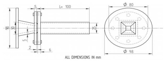
Figure 6. Dimensions of the nozzle and the duct [6].
Another study [7] on the cavity found that semi-circular grooves reduces the base drag in the backward-facing step. Here two semi-circular grooved cavities are placed at 45° across the PCD of 23 mm at the base. For the experiment, the square nozzle is used of 10 mm side, with a duct length of 150 mm of side 25 mm. Three duct lengths are considered for investigation, and they are 4 W, 6 W, and 8 W.
It is apparent that the base pressure has substantially increased, and its reliance on flow parameters like Mach number and L/W ratio is exhibited. Therefore, the base pressure is slightly higher than the ambient pressure. Grooved cavities have a significant effect on the increase of base pressure. Thus, all the Mach numbers considered in the study [7] have reduced drag with lower pressure and minimized the recirculation zone. Below, Figure 7 shows a square nozzle and grooved control plate.
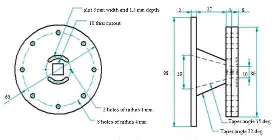
Figure 7. Square nozzle and grooved control plate [7].
Pressure variations in the base of a standard freestream missile configuration in the presence and absence of passive control in the form of the base cavity at a Mach number of 0.7 are investigated experimentally by Vikramaditya, N. et al. [8]. The aim was to identify base pressure variations and explain the impact on base cavities’ behavior. Experiments involve unstable pressure measurements in six azimuthal areas. Due to the model’s asymmetry, there is considerable variation in the pressure fluctuations in the azimuthal direction.
The base cavities increase the base pressure and reduce the average root square of the base pressure. When the base cavity is enhanced, the higher-order moments show a decreasing trend. High amplitude, low-frequency oscillations, autocorrelation, and cross-correlation plots are observed for cavities of significant length. Virtually no fluctuations are noticeable in the model with a cavity with minimal size.
The mean azimuthal pressure variation is recorded and analyzed for various cavity structures on the projectile base. In contrast with the BB model, higher values of the foundation pressure coefficient are noted for the SC model except at an azimuthal position of 270 deg. That is because the base cavity increases the recirculation region’s size, and flow also travels downstream of the base separation point.
This reduces the interaction between the shear layer and the recirculation field. However, the separation point’s relocation results in less contact between the base and the low pressure associated with the shedding vortex. The average base pressure coefficient at all azimuthal locations is −0.08. Due to the pressure difference between the freestream and the recirculation region, the ventilated cavities act as natural bleeding tools.
The fluid mass is injected into the base area by bleed devices, thus increasing the base pressure. There is no significant increase in the SVC model’s base pressure than the SC model (at the corresponding sensor sites) except the 270 deg azimuthal position. The probability may well be that the normal component of the momentum fluid flow in the base region through the vent holes is negligible. It means that the area of the recirculation will be insignificantly massed.
All the vent holes on the cavities are usually directed to the freestream flow in the present study. Thus, the effect of increasing base pressure due to the natural bleeding process is negligible. In general, the base pressure increases due to the lower interaction of base and the low pressure associated with the vortex deposits, as explained earlier, when the ventilated cavities size is changed from small to large. The findings of a numerical and experimental analysis studied by Mariotti et al. [9] reported assessing a control process’s performance to postpone the boundary layer’s separation.
This process consisted of incorporating the surface of contoured, transverse grooves (i.e., small cavities with an acceptable cross-sectional shape). The grooves’ shape and depth need to be significantly smaller than the incoming boundary layer’s width; fluid recirculation within the grooves is smooth and stable. This strategy is applied to an axisymmetric bluff body with different rear boat ends, distinguished by numerous flow-separating degrees. Variation of large multiscale eddy simulations was examined experimentally [9].
Before boat tails, the boundary layer conditions are fully developed turbulent in experiments and intermediate in simulations due to the different input flow turbulence levels. Every time a single axisymmetric groove is added on the boattails’ lateral surface, the boundary layer’s separation is postponed considerably, and the pressure drag is reduced. The wake-dynamic structure remains qualitatively similar.
It was analogous to an asymmetrical bluff body with quantitative variations that correlate with the wake width of a reduction caused by boattails and grooves. A few additional simulations show that the groove effect is also resistant to change the geometric parameters that define its shape. Both evidences support the notion that relaxing the no-slip boundary condition for the flow around the recirculation regions at an appreciable pace on their boundaries is the physical mechanism responsible for the new separation control method’s efficacy.
Several techniques are explored to reduce the aerodynamic drag of bluff bodies through base pressure recovery. These include boat tailing and base cavities. Howell et al. [10] changed Ahmed’s body to have a base cavity of variable depth that may be ventilated via a slot in a square-back configuration considered for investigation. The overall body drag diminished with a single cavity for numerous cavity lengths, but a distinct minimum drag state was achieved.
A relative drag reduction is achieved by the incorporation of ventilation slots and at a much-reduced cavity size. The pressure data in the cavity was used to assess the dependence of the base drag. Variations in the slot structure were analyzed to decrease the drag and the slot distribution effects. PIV is used for various cavity setups. Figure 8 shows Ahmed’s body with vented slots [10]. The base pressure was assessed on the cavity backplate. There was a total of 48 pressure tubes spread over one half of the backplate.
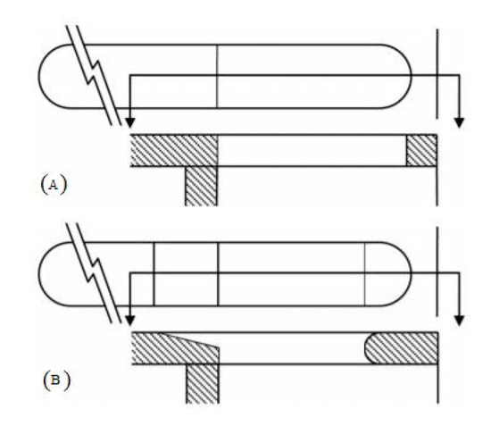
Figure 8. Ventilation slots details (A) with square-edged (B) tapered [10].
Numerous cavity configurations were tested at the ground level [10]. The cavities were the plane cavity, the original vented cavity with square edge slots, the vented cavity with tapered slots on all surface areas, and the same cavity with undesirable slots covered. For both earlier settings, the standard pressure measurements were made for the ideal cavity and a much deeper cavity. The pressure measurements were undertaken for various cavity depths in the two ventilated cavities with tapered holes. In each case, comparisons were made with the base pressures calculated without a cavity on the quarterback scale.
Seeing the growing need for energy conservation, Bonnavion et al. [11] researched the reduction of base drag. Here the author has studied the Ahmed body [12] as the bluff body for the real-time road vehicle. Experiments were conducted to investigate the bifurcation of the wake controlled by the clearance and impact of the base cavity before and after bifurcation that can be used when making road vehicles. It is observed that regardless of ground clearance, above the threshold 5c* = 0.08, an eight percent reduction is achieved.
Lucas et al. [13] did a numerical investigation of the asymmetric wake mode of a square back Ahmed’s body, focusing on a base cavity effect. Both distributions indicate an almost identical pressure field for the baseline and shallow cavity for x > 0.5. While they are horizontally and vertically shifted from each other for x < 0.5. They both present a local minimum, with good shape indicating the presence of a viscous vortex flow (i.e., the circular recirculation) source of low pressure.
The horizontal shift appears to be introduced by the cavity depth of d = 0.047, indicating that the circular recirculation region remains at the same distance from the body’s base. The vertical shift is introduced in the area 0.33 < x < 0.5. The pressure gradient with the cavity is reduced compared to that of the baseline. Again, an exact horizontal shift corresponding to the cavity depth is observable between the baseline and the shallow cavity. The viscous vortex interaction with the base leads to the same maximum velocity close to the base, and the velocity gradients are very similar for x < 0.33.
2.2. Passive Control with Rib
As cavities introduce secondary circulation in the flow, it reduces the oscillatory nature of flow and increases the base pressure. This phenomenon is more prominent in longer ducts than in shorter ducts. However, the cavity’s main disadvantage is when it starts behaving like a closed cavity, thereby becoming ineffective as a passive control. As a result, in 2001, Rathakrishnan [14] introduced ribs as a passive control device. He employed five ribs in the circular duct diameter of 25 mm of aspect ratio 3:1, 3:2, and 3:3 at 1D (D = diameter of the tube) location. From his results, he found out that the 3:1 is the most effective in reducing the base drag.
For pressure ratio 1.141, the base pressure attains the minimum value for L/D = 4 due to the shear layer extending from the nozzle outlet connects downstream of the base to the extended duct wall [14]. The primary vortex formed at the base region affects the base pressure according to the distance of the reattachment point from the base region and the Mach number at the nozzle exit. The primary vortex intensity determines the low-pressure level in the base region. There exists a reverse flow due to the low-pressure zone created by the vortex. The passive control in the form of the ribs comes into effect in this separated flow.
Later Yedlapalli et al. [15] introduced ribs with aspect ratios 0.45, 0.64, 0.84, and 1.25 at X/D = 0.5, 1, and 1.5, placing a single rib at three different locations in a circular pipe of 22 mm diameter at subsonic to sonic Mach numbers (0.2 to 1). The results show that the rib aspect ratio between 0.45 and 0.64 reduces the backflow and reduces the base pressure. From wall pressure distribution results, it is found that ribs with the smallest aspect ratio, i.e., 0.45 at X/D = 1, gives the minimum disturbance along the pipe while gaining desired base pressure results.
Nathan et al. [16] studied the effect of the annular ribs of aspect ratio 3:3 at supersonic Mach number 1.8, varying the NPR from 2 to 6 at locations 0.5D, 1D, 1.5D, 2D, 3D, 4D, and 5D in a circular pipe. It is noticed that the base pressure increases with an increase in the NPR with rib location. Vijayaraja et al. [17] also studied the annular ribs experimentally with aspect ratio from 0.45 to 1.25 placed in enlarged duct by varying the length to diameter ratio (L/D) 0.5D to 6D, and NPR is varied from 1 to 7 at subsonic to sonic Mach numbers. It is realized that L/D = 0.5 for NPR 3, the base pressure increases with an increase in NPR.
Khan et al. [18] did the numerical simulation and studied the flow at the sonic Mach number for a duct diameter of 20 mm. A single rib of three different aspect ratios (3:1, 3:2, and 3:3) is placed one at a time at various locations (1D, 2D, 3D, and 4D) along the circumferential direction of the duct. It is concluded that the increase in NPR is from 1.5 to 5; the base pressure decreases continuously with no rib case.
In contrast, with the rib case, the base pressure decreases steadily with aspect ratio 3:1, while for aspect ratio 3:2 and 3:3, it raises the base pressure at NPR 2.5 and 2, respectively. It was also clear that for no rib case, the base pressure decreases continuously, and for rib case 3:1, there is continual decrement of base pressure; however, it is above the base pressure of the smooth pipe. For 3:2 and 3:3, the base pressure starts to increase from NPR 2.5 compared to 3:1, where the base pressure starts to grow right from the beginning, i.e., NPR 1.5. Figure 9 shows the same.

Figure 9. Base pressure changes when NPR is increased from 1.5 to 5, and the aspect ratio is changed from 3:1 to 3:3 [18].
The main reason behind this phenomenon is that with an increase in NPR, the expansion level increases. As the reattachment point has shifted as the flow is highly under expanded, the primary vortex’s effectiveness decrease. There is a reduction in fluid reversal, as there is an introduction of secondary vortices due to rib height, due to which base pressure increases. This phenomenon is considerable for the 3:4 aspect ratio as the rib height has increased.
2.3. Passive Control with Dimple
The research on passive control in the form of a dimple is done by Khan et al. [19]. They investigated both experimentally and numerically the passive control effect to control the base pressure in a Backward Facing Step at various NPRs. Two dimples of diameter 3 mm are located at 180° intervals at the base region along the Pitch Circle Diameter of 23 mm. This study was done for NPR 1.27, 1.38, 1.52, and 1.69. Figure 10 shows the design and dimensions of the nozzle and the duct.
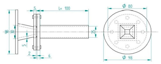
Figure 10. Dimensions of nozzle and duct [19].
The model is designed to deliver four BFS with an incidence angle of 15° from which the flow expands suddenly to a 25 mm square duct for different duct length 4D ≤ L ≤ 10D to see the effect of the base pressure’s geometric parameter. The presented investigation revealed that the passive control dimples are highly effective at higher NPR, and the wall pressure distribution at higher NPR too was stable. The spatial parameter also affected the base pressure for a particular NPR.
CFD analysis was also done on the dimple and dimple with pressure and velocity distribution profile using the Navier stokes equation, Turbulence model SST, and Reynold’s number (Re) = 122.56 × 10³. From this analysis, it is clear that an optimal L/D ratio can be found for a given nozzle pressure ratio, which results in a maximum increase/decrease in base pressure, and the passive controller can be efficient in controlling the base pressure.
Findings state that the level of expansion (NPR) strongly affects the base pressure and influences dimple as a passive control. At higher NPR, it is found that the base pressure is low, and hence dimples as passive control are very effective in controlling the base pressure if achieving the low base pressure is the mission requirement. For example, in the combustion chamber, we want to achieve a minimum base pressure for better fuel-air mixing to enhance its efficiency.
2.4. Passive Control with Static Cylinder
It is known from the experiments of passive control in the form of a static cylinder that when the flow is correctly-expanded and under-expanded, the passive control in the form of a stationary cylinder becomes useful. Asadullah et al. [20] did a wind tunnel experiment (Figure 11) using the static cylinder at supersonic Mach number 2 by varying the NPR from 2 to 9. It is observed that when the NPR is low (i.e., up to NPR 5), there is no effect of control on the base pressure values, whereas, for the higher NPR (i.e., NPR = 6 and above), the control begins to show its effectiveness and the change in the base pressure increases until NPR 9.
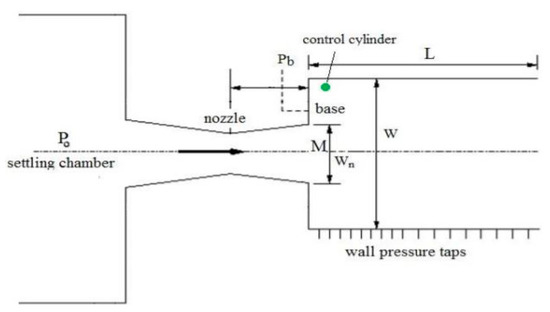
Figure 11. Experimental setup [20].
The percentage change in base pressure is 14% at NPR 6, and this trend increases and reaches up to 59% at NPR 9. The jet is over-expanded till NPR 6, and after NPR 6, and at higher NPRs, the flow is correctly-expanded or under-expanded. This is the leading cause of the significant increase in base pressure due to the flow interactions with the shock at the square outlet region, and it makes the vortex weak in the base region. Thus, the NPR increases and over-expansion reduces, and a weak oblique shock is present compared to lower NPR.
2.5. Passive Control in the Form of Spikes
An experimental study was done on the bluff body at subsonic Mach numbers. Passive control in the form of aerospikes was placed on a plate of 1 mm thickness. Two spikes are placed on the plate at 11.5 mm between the nozzle and the duct. The tests were conducted at Mach numbers 0.6, 0.7, 0.8, and 0.9 for an area ratio of 6.25. L/W ratios of the duct taken into consideration are 4, 6, 8, and 10. These experiments were undertaken to control the base drag, an essential component in bluff bodies, to reduce the total drag [21]. Figure 12 below shows the placements of aerospikes.
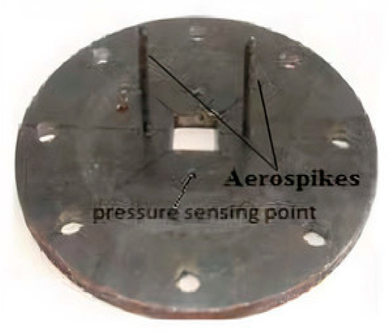
Figure 12. Control plates with aerospike [21].
Findings stated that without control case, the base pressure first increases till L/W = 6 and then decreases till L/W = 8, and then is an increasing trend in base pressure until L/W = 10. With passive control of aerospike, the base pressure starts to increase right from the beginning and becomes more than atmospheric pressure at L/W = 6, and then again, as an increasing trend, it continues till L/W = 10. It acquires the pressure value, which is 5% more than atmospheric pressure.
The main reason for this phenomenon is that until L/W = 6, the aerospikes can break the base region’s recirculation zone into two parts. Hence, the suction at the base is reduced, and the base pressure increases. Also, from L/W = 4 to L/W = 6, the duct’s length is small. So, the two recirculating bubbles formed at the base get less space to travel. Whereas from L/W = 7, till L/W = 10, the duct’s length is more and hence gets more space and time to travel, and therefore the base pressure gradually increases with the L/W ratio. However, the aerospike in passive control is very useful at the subsonic and transonic regimes.
Mehta [22] studied a forward-facing aerospike to a satellite launch vehicle. The payload fairing significantly modifies its flow field and reduces the aerodynamic drag at transonic and supersonic speeds. The numerical simulation was carried out on 0.8 ≤ M ≤ 3.0 with and without aerospikes. A forward-facing aerospike attached to a payload fairing of a satellite launch vehicle significantly altered its flow field and decreased the aerodynamic drag in transonic and low supersonic speeds.
The present payload fairing is an axisymmetric configuration and consists of a blunt-nosed body along with a conical section, payload shroud, and boat tail, followed by a booster. All pressure transducer loss is below the average order of ±0.51%. In general, there is good agreement between the current computations and the available experimental data. When an aerospike is attached to the payload fairing, the payload fairing pressure is changed considerably. The reduction of surface pressure is not minimal for M < 1. There is a significant drop in surface pressure for M > 1.
Another study was done by Khan et al. [23] on threaded spikes as a passive control. In their research, as shown in Figure 13, two threaded spikes were attached in the opposite direction of length 40 mm on the circular plate of thickness 1 mm and diameter 80 mm. They conducted tests for Mach numbers (0.6 and 0.7) and two transonic Mach numbers (0.8 and 0.9). Ducts of lengths 100 mm, 150 mm, and 200 mm are examined.
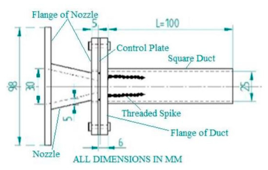
Figure 13. Square nozzle with threaded spikes control plate [23].
Khan et al. [23] findings for L/W = 4 show that base pressure continuously decreases with an increase in Mach number without control. With the control case, there is an increase in base pressure, i.e., it is more than atmospheric pressure right from the beginning and decreases till Mach number 0.7 and then again increases till Mach number 0.9. For L/W = 6, the increase in base pressure with the control case was from Mach 0.6 to 0.9.
For L/W = 8, there is an increase in base pressure until Mach 0.7 and then a slight decrease to 0.8 and a steep increase in base pressure until Mach 0.9. However, for L/W ratios, it can be observed that there is an increase in base pressure right from the beginning compared to no control case, and it is more than atmospheric pressure.
This entry is adapted from the peer-reviewed paper 10.3390/app11031334
This entry is offline, you can click here to edit this entry!