A new approach in the development of aircraft and aerospace industry is geared toward increas-ing use of electric systems. An electromechanical (EM) piezoelectric-based system is one of the po-tential technologies that can produce a compactable system with a fast response and a high power density. However, piezoelectric materials generate a small strain, of around 0.1–0.2% of the original actuator length, limiting their potential in large-scale applications.
- piezoelectric stack
- amplification mechanism
- quasi-static stepped system
- ultrasonic system
- pie-zoelectric-hydraulic
- aerospace applications
Note: The following contents are extract from your paper. The entry will be online only after author check and submit it.
1. Introduction
A concept of more/all-electric aircraft has recently received huge attention in the research and development work in the field of aerospace engineering [1–7]. The intent is to use more electrical systems in aircraft and aerospace applications to bring an impact on the environment [8]. With the fast development of electrification, more researchers and manufacturers are shifting to this dynamic trend involving a high demand for increasing the load, improving fuel efficiency, reducing emissions, and lowering the total cost of operation. Researchers seek different approaches and technologies to broaden this fashionable concept in a wide range of applications. The choice of actuators in the aircraft is based on various critical factors, such as power density, reliability, efficiency, control features, and thermal robustness, as well as the weight, size, and maintenance cost. In a commercial aircraft, actuators are essential in various applications, such as flight control, engine starter, landing system, brake actuation, and fuel pump [9,10]. The specifications of actuators in an aircraft vary across a wide range. Typical requirements can be listed as 1–320 of force, 10–700 of stroke, and 10–500 of speed, with the requirement of both modulated and two-position control methods [4,11]. For these actuation systems in the aircraft engine, the working temperature is from −50 to 150 °C at the engine intake; and it is higher for the actuators located toward the high-pressure compressor void (300–400 °C) or the tail cone area (500–600 °C) [12]. Overall, actuators in an aircraft require both the advantages of materials that allow them to deliver the required power in extreme environmental conditions and the optimal structural designs to maximize their performance within a constrained weight and space.
In the development of signal-by-wire and power-by-wire actuators in aircraft, electromechanical (EM) systems have seen a huge improvement, with significant results from both researchers and manufacturers. Electrical actuators, which have taken advantage of state-of-the-art motors and power screws, are among these systems [13–17]. The electrical actuators could provide a load range of up to 90 , with over 90% efficiency, making them suitable for replacing several conventional hydraulic or fueldraulic systems in the jet engine [18,19]. These systems bring more advantages in terms of a compact design (eliminating pipes and heavy elements) and power-to-weight ratio (weight reducing), enhancing aircraft stability and thus providing the ability to incorporate more functions within the control system to further enhance aircraft utility. Besides electrical actuators, smart-material-based actuators are also considered a promising approach. The development of smart materials, such as piezoelectric materials [20], shape memory alloys [21], magnetostrictive materials [22], and electroactive polymers [23,24], also offers advantages in the aerospace applications [25,26]. Looking beyond the potential of replacing the conventional system with similar or even better performance actuators, the smart behavior of such materials may offer more room for the development of novel systems. For example, the shape-changing ability of smart materials can be explored in morphing aircraft [27,28]. Shape memory alloy-based [29,30] and piezoelectric-based bender designs [31] can be used for noise reduction when mounting the bender on the trailing edge of the jet engine fan nozzle and the rotor of the helicopter, respectively. Each material responds differently to the stimuli, and various actuation modes can be achieved with distinct working concepts and geometrical designs. Among them, piezoelectric materials have shown great potential in aircraft and spacecraft applications [32–36]. The definition of piezoelectric materials is that they can either generate an output voltage when subjected to mechanical stress or perform a dimensional change when subjected to an electric field. These phenomena are known as direct and indirect modes of operation, which can be used for generators [37], sensors [38], and actuators [39]. Piezoelectric materials have the advantages of high power density, high efficiency, driving force, and displacement resolution over electromagnetic materials. They also do not generate electromagnetic noise and are nonflammable [40–42]. Piezoelectric materials come in different forms, such as sheet, wafer plate, stack, fiber, and composite, which makes them suitable for diverse geometrical designs. Despite a minimal strain capability, piezoelectric actuators can deliver high power outputs with high efficiency due to their ability to be cycled at very high frequencies as compared with other actuators [43] (Figure 1).
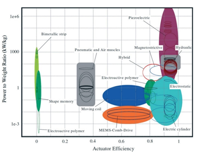
Figure 1. Power-to-weight ratio versus efficiency from a database of 220 actuators (from [43]).
Some piezoelectric materials can work in a very large temperature range, making them more promising in aircraft applications. A report from NASA revealed positive results of four piezoelectric ceramics, namely PZT-4, PZT-5A, PZT-5H, and PLZT-9/65/36, from several tests to evaluate their applicability as sensors and actuators in the intelligent aerospace system over a large temperature range, from −150 to 250 °C [44]. More efforts on material development were recorded that would gradually enhance the potential of piezoelectric materials in high-temperature industrial applications [45,46]. Therefore, piezoelectric-based systems are possible for applications located in the cold section of the aircraft engine, in which the temperature varies from –50 to 250 °C. However, amplification methods are required to generate sufficient stroke for these applications. The specifications of suitable applications for a compact piezoelectric design should be in the range of up to 5 of force, 100 of stroke, and 50 of speed. Thus the high stress and working frequency of piezoelectric actuators can be advantageous within a compact system. Some applications could be variable blow-in doors, booster bleeds, variable inlet guide vanes (IGVs), and variable stator vanes (VSVs). For instance, a piezoelectric-based linear actuator with a crank-slider mechanism was proposed to drive the IGV, which helps to control the flow that enters the jet engine and to improve the efficiency of the compressor [47,48]. Sufficient stroke of the actuator is accumulated over repeated cycles. For the same application (IGV or VSV of the gas turbine jet engine), the piezoelectric system could also be designed in such a way that a rotary motion can deliver directly to the application [49]. This actuator can be mounted on the unison ring, thus eliminating the need for other mechanical structures that add extra weight to the system. Moreover, the ability of power-off holding position of piezoelectric materials allows a design that can maintain the last controlled position in the event of failure, thus enhancing the safety level in aircraft applications.
2. Piezoelectric Actuators
2.1. Fundamentals of Piezoelectric Materials
The piezoelectric effect on ceramic materials was discovered in 1880 by Nobel laureates Pierre and Jacques Curie. A piezoelectric transducer can be used as both generator [50] and actuator [51]. Specifically, the direct piezoelectric effect is used in the generator, while the indirect piezoelectric effect is used for the actuator [52]. The direct piezoelectric effect refers to the development of electrical charges on applications of mechanical stress, and vice versa (indirect piezoelectric effect). For the actuation applications reviewed in this paper, the piezoelectric material deforms with the applied electric field to produce mechanical energy.
The most commonly used piezoelectric materials are piezoelectric ceramic, such as lead zirconate titanate (PZT), barium titanate (BaTiO3), and lead titanate (PbTiO3). With a polycrystalline structure, ceramic materials can be fabricated into a variety of shapes and sizes. Besides, with the effort to reduce and avoid lead (Pb) in piezoelectric materials, lead-free piezoelectric development has been gaining momentum in recent years [20,53–55]. Some of these materials are alkali-metal-based bismuth sodium titanate (BNT), bismuth potassium titanate (BKT) [56], and potassium sodium niobate (KNN) [57]. To increase the potential of piezoelectricity in various working conditions, high-temperature piezoelectric materials have been developed, such as Pb(NbO3)2 and Bi4Ti3O12 [45]. However, the strain and stress of these materials may be reduced. In general, piezoelectric materials have a very small strain, of 0.1–0.2%, but with high stress, in the range of 100–131 MPa. Their specific power density is around 1000 kW/kg, and they have high efficiency, of more than 80% [40,43,58]. However, piezoelectric materials experience some drawbacks, such as substantial hysteresis [59], temperature-dependent properties [60], and fracture behaviors [61]. These phenomena eventually affect the performance of the piezoelectric materials, especially the stroke and accuracy of piezoelectric actuators.
The performance of the piezoelectric actuator is determined by the material properties known as the electromechanical coefficients. The most common material properties are the directional piezoelectric charge constants. The mechanical strain () of a piezoelectric material can be found by the relation
 |
(1) |
where is the compliance or elasticity coefficient, is the mechanical stress, is the piezoelectric charge constant, and is the electric field (, where is the applied voltage and is the thickness of the material).
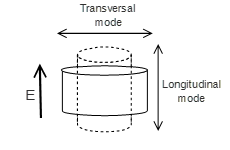
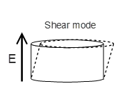
The coupling coefficient of the piezoelectric can be divided into three groups corresponding to the orientations of the electric field and the displacement. These coefficients are , , and , corresponding to three deformation modes: longitudinal, transversal (Figure 2a), and shear modes (Figure 2b), respectively. In general, the strain and electromechanical conversion efficiency are higher in the longitudinal direction [62,63]. Therefore, this deformation mode is usually used in actuators, especially in the stacked configuration. Table 1 below shows examples of some piezoelectric materials and their properties that are commonly used in the piezoelectric-based system.
 |
 |
|
(a) |
(b) |
Figure 2. Deformation of the piezoelectric actuator. (a) Longitudinal and transversal mode; (b) shear mode.
Table 1. Examples of some properties of piezoelectric materials.
|
Materials |
at Room Temp. (pC/N) |
Curie Temp. TC (°C) |
Operating Temp. (°C) |
Reference |
|
PZT powder |
590–610 |
- |
- |
[20] |
|
PMN-PT |
2000–3500 |
120–130 |
Up to 80 |
[42,60] |
|
PZN-PT |
1900–2000 |
160 |
Up to 110 |
[42,64] |
|
PZT-5H |
585 |
170 |
−150–125 |
[44] |
|
PZT Navy Type III (Hard) 1 |
<300 |
305 |
Up to 220 |
[45] |
|
PZT-4 |
225 |
310 |
−150–100 |
[44] |
|
PZT Navy Type II (Soft) 2 |
<600 |
340 |
Up to 200 |
[45] |
|
PZT-5A |
350 |
350 |
Up to 250 |
[44] |
|
PIC series |
240–500 |
160–370 |
−40–150 |
[65] |
|
Lead-free materials |
|
|||
|
BTBK |
58.9–117 |
170–223 |
- |
[56] |
|
BNT |
91 |
320 |
- |
[56] |
|
KNN |
80–160 |
Up to 400 |
- |
[57] |
|
High-temperature materials |
|
|||
|
Pb(NbO3)2 |
81 |
550 |
Up to 300 |
[45] |
|
Bi4Ti3O12 |
3.5 |
675 |
Up to 675 |
[45] |
|
Bi4Ti2.86Nb0.14O12 |
20 |
655 |
Up to 655 |
[45] |
1 Hard: less hysteresis loss, good stability under high mechanical loads, and operating field strength; thus good for ultrasonic transducers. 2 Soft: large hysteresis loss, large piezoelectric charge coefficient, and easy polarization at low field strength; thus ideal for actuator and sensor applications.
Piezoelectric elements can come in different geometrical forms, such as thin plate, single layer, multilayer, torsion tube. Besides these designs, macro piezo fiber composite (MFC) is another form of piezoelectric that was invented by NASA back in the 1990s and has been commercialized by Smart Material since 2002 [66,67]. Constructed of piezoelectric-ceramic-based fibers (usually PZT 5A or PZT Navy Type II) sandwiched between electrodes and polyimide layers, MFCs can produce elongation, contraction, and bending motions for actuation [68]. They can also function in sensitive sensor and vibration harvesting applications [69,70]. With a flexible nature, these piezoelectric composites have greater durability and reliability and can be attached to the surface of or embedded inside the structures. They have been proposed to be used in various aerospace applications, such as aircraft health structure monitoring, noise and vibration control of helicopter rotors, and surface control of morphing wings [67,69,71]. MFCs can find more aerospace applications if high-temperature piezoelectric (see Table 1), electrode, and adhesive materials are explored [72]. Table 2 below summarizes the performance of commercial piezoelectric actuators with some typical geometrical forms.
Table 2. Typical displacement and resonant frequency of typical geometrical forms of commercial piezoelectric actuators.
|
Form |
Typical Size |
Displacement Range |
Resonant Frequency |
|
Single layer (wafer) |
A few hundred micrometer thickness |
Up to 0.1 |
Up to 100 |
|
Multilayer extension (rectangle, round, hollow stacks) |
Up to 100 area & 100 in length |
Up to 100 |
Up to 100 and more |
|
Multilayer shearing |
Up to ~250 area & 50 length |
Up to 10 |
Up to 100 and more |
|
Piezo bender (unimorph/bimorph) |
<1 thickness |
10 to 2 |
Up to a few kilohertz |
|
Macrofiber composite (elongation) |
Up to 140 active length |
Up to 1501 |
From to megahertz |
|
Macrofiber composite (contraction) |
Up to 170 active length |
Up to 100 2 |
From to megahertz |
1 Free strain: up to 1050 ppm. 2 Free strain: up to −600 ppm.
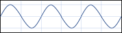
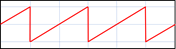
The piezoelectric actuator can be powered by a periodic voltage with sinusoidal, sawtooth, or rectangle waveforms. Depending on the required movements, each piezoelectric mechanism requires a customized input signal with a particular pattern, amplitude, and frequency to maximize its performance. In the event of more than one piezoelectric element being involved in the design, the phase difference of the controlled signal of each piezoelectric actuator needs to be designed precisely to obtain the coupling performance. The sinusoidal, square/rectangle, and sawtooth waveforms are commonly used in the stepped-motion piezoelectric system (Table 3). Power consumption during the operation of piezoelectric actuators is directly proportional to the capacitance of the device by the relation shown in Table 3.
Table 3. Typical input signals and related power consumption for piezoelectric actuators.
|
Sinusoidal Waveform |
Square/Rectangle Waveform |
Sawtooth Waveform |
 |
 |
 |
|
|
 |
 |

where is the working frequency, is the capacitance of the piezoelectric, and is the applied peak to peak voltage. The piezoelectric heat dissipation is usually 10% of the power supplied to the load. Therefore, the selection of usage piezoelectric materials and operating conditions must be weighed against the consumed power to ensure that the system’s power budget is optimized.
2.2. Piezoelectric Stacks
Piezoelectric materials can be stacked together and be sandwiched between electrode layers to achieve a higher stroke for actuator applications [73,74]. Adopting the name of the manufacturing method, they are known as the piezoelectric stack or the multilayer piezoelectric (Figure 3). Piezoelectric stacks and piezoelectric actuators are manufactured and developed by various companies, such as Physik Instrumente (PI), Tokin Corporation, Cedrat Technologies, PiezoDrive, PiezoMotor, Piezosystem Jena, and CTS Corporation. Usually, the length of the stack is limited to 150 and the area is less than 225 2. The commercial piezoelectric stack usually offers a stroke range from several micrometers to a hundred (longitudinal mode) and a blocked force range from a hundred to a few thousand . The size and shape of a piezoelectric stack can be customized to generate the required force and stroke. In the case of large stroke applications, an amplification mechanism is preferred.
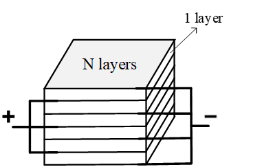
Figure 3. The electrical connection of an N-layers piezoelectric stack.
The stroke () of the stack is scaled with the number of stacking layers (Equation (2)), while the output force () is related to the active area of the piezoelectric actuators
(Equation (3)).
 |
(2) |
 |
(3) |
where, is the piezoelectric constant (longitudinal mode), is the number of stacking layers, is the modulus of the piezoelectric material, is the area of each layer, and is the initial thickness of each layer. The force and stroke of the piezoelectric stack are under an electrical load (applied voltage ), and the mechanical load is shown in
Figure 4. When the piezoelectric stacks are implemented in a cyclic process, they will be subjected to a severe hysteresis characteristic affected by the frequency and magnitude of the applied voltage. Therefore, closed-loop control is required to compensate for the hysteresis effect in precise positioning applications [59,75].
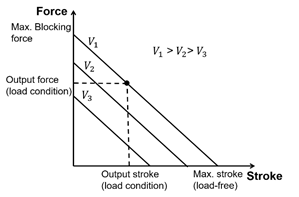
Figure 4. Force–stroke characteristic of the piezoelectric stack.
2.3. Classification of Amplification Methods
The microstroke range of a stand-alone piezoelectric stack can be further amplified to the required level using external amplifiers, such as mechanical, hydraulic, or other kinetic mechanisms, depending on the architecture. Several conceptual designs are proposed and used, such as the amplified mechanism by the compliant structure, the inchworm mechanism, the walking mechanism, and the hybrid electro-hydraulic system. In this paper, the amplification methods are divided into four groups, as shown in Figure 5. Each technique will be discussed in subsequent sections.
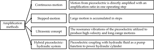
Figure 5. Summary of amplification methods.
This entry is adapted from the peer-reviewed paper 10.3390/mi12020140