Fuel cell electric vehicles, which optimally combine the fuel cell system with hybrid energy storage systems, represented by batteries and ultracapacitors, to meet the dynamic power demand required by the electric motor and auxiliary systems.
- fuel cell electric vehicle
- DC/DC converter topolo
Note: The following contents are extract from your paper. The entry will be online only after author check and submit it.
1. Introduction
In order to continue using fossil fuels, which means 80% of the world’s energy demand, there are two main problems [1].
The first problem is the limited amount of fossil fuel, and sooner or later these sources will be consumed. Estimates of petroleum companies show that by 2023 there will be a peak in the exploitation of fossil fuels, petrol and natural gas, and then they will start to decline [2].
The second and most important problem is that fossil fuels cause serious environmental problems such as: global warming, acid rain, climate change, pollution, ozone depletion, etc. Estimates show that the worldwide destruction of the environment costs about $5 trillion annually [3].
The solution proposed for the two global problems first appeared in 1970 as the “Hydrogen energy system” [4]. In the last decade through research and development work in universities and laboratories of research institutes around the world shows that hydrogen is an excellent source of energy with many unique properties. It is the cleanest and most efficient fuel [5].
The unique property of hydrogen is that it can be directly converted into electricity in the fuel cell system which makes it much more efficient than the conversion of conventional fuels into mechanical energy [6].
This unique property of hydrogen has led to the manufacture of hydrogen fuel cells and makes them a very good choice for automotive companies [7].
The alternative to fossil fuels found by car manufacturers for fueling vehicles is represented by other energy sources, such as: battery systems, ultracapacitors or fuel cells. Electric Vehicles (EVs) and Fuel Cell Electric Vehicles (FCEVs) are the most viable solutions for reducing Greenhouse Gases (GHG) and other harmful gases for the environment. Although EVs and FCEVs can reduce emissions to a certain value, they do not reduce them to absolute zero [8].
Thus, the renewable energy transport infrastructure allows FCEVs to become a preferable choice, because they preserves the range autonomy in the road and rail transport sector (and not only), without using fossil fuels [9]. FCEVs and FCHEVs use a combination of Fuel Cells (FC), and batteries (B) or/and Ultracapacitors (UC) [10]. The research stages for FCHEVs include the development of vehicles and the improvement of their efficiency. Beside the fuel cell system, they use the battery and/or ultracapacitor pack as a complementary power source to provide the required power on the DC bus. The topologies of FCEVs are described in detail in [11].
To increase the power density and to meet the demand for load power, it is necessary to integrate an energy management system. The energy management strategy of FCEVs is based on many important control techniques [12] such as finite state machine management strategies [13], grey wolf optimizer [14], model predictive control [15,16], fuzzy logic control [17,18], genetic algorithms [19,20], hierarchical prediction [21,22] as well as other control techniques developed so far for the energy management system.
2. Topologies of Propulsion Systems and the DC/DC Converters of FCEVs
All Electric Vehicles (AEVs) use only electric power to propel vehicles. AEVs can use as energy backup source a stack of batteries, a Fuel Cell (FC) stack or a hybrid solution, the AEVs being called as Electric Vehicle with Battery (BEV), EV with FC (FCEV) and hybrid EV with FC (FCHEV). In the following we will focus on the last two types [8,23]. Below, Table 1 presents a summary description of FCEV’s and Fuel Cell Hybrid Electric Vehicle (FCHEV’s) topologies.
When it comes to the problem of EMS optimization, it is first necessary to understand the features and modes of operation of the propulsion systems topologies. Multiple topologies have different configurations in terms of design, by modifying the power source connection [24].
Because the direct connection to the electric motor of the vehicle is not efficient due to the different voltage levels of the fuel cell, the battery system and the ultracapacitor, as will be reported in Section 2.1, it is necessary to integrate the DC/DC converters to generate the voltage required by the electric motor [25]. Thus, in the Section 2.3 an analysis of the types of DC/DC converters used in FCEV is described [26].
2.1. Fuel Cell Electric Vehicle (FCEV)
FCEVs use a full electric propulsion system, and the energy source is based on fuel cell stacks. A FCEV is hydrogen-fueled and the electrochemical process results in water and heat. PEMFC is the ideal choice compared to other types of fuel cell system (FCS) because it operates at a low temperature of 60–80 °C, develops a high-power density and exhibits low corrosion [27].
FCEVs powertrain can be separated into three categories: fuel cell and battery (FC + B), Fuel Cell + Ultracapacitor (FC + UC) and Fuel Cell + Battery + Ultracapacitor (FC + B + UC) [28]. Because FC + B + UC configuration is complex and due to the fact that ultracapacitors have low energy density, FC + B is the main design configuration and is applied in most FCEVs [29].
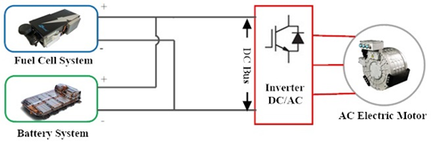
According to FCEVs topologies, FC + B can be divided into four categories (see Figure 1).
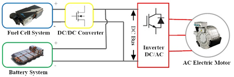
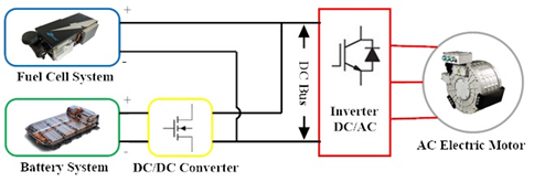
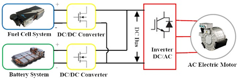
In the first topology, T1, FCS and the battery system are connected directly to the DC/AC inverter of the motor, without a DC/DC converter (Figure 1a). In the second topology, T2, FCS is connected by a DC/DC converter, the battery system being directly connected to the DC bus (Figure 1b), the advantage being to facilitate the power distribution between the FCS and the battery system. In the third topology, T3, the battery system is connected by a DC/DC converter, FCS being directly connected to the DC bus (Figure 1c). The fourth topology, T4, is the most preferred in research because it has a great flexibility in controlling the power flow for both FCS + B systems (Figure 1d) [30].
 |
|
(a) |
 |
|
(b) |
 |
|
(c) |
 |
|
(d) |
Figure 1. Topology of Fuel Cell Electric Vehicles (FCEVs): fuel cell + battery. (a) Topology T1; (b) Topology T2; (c) Topology T3; (d) Topology T4.
2.2. Fuel Cell Hybrid Electric Vehicle (FCHEV)
Any new modification to the propulsion system at the initial configuration of the FCEV, represents a new architecture respectively a new vehicle, namely Fuel Cell Hybrid Electric Vehicle (FCHEV). The new resulting architecture is based on New Energy Storage Systems (ESS) being in energy support for the fuel cell system. The energy storage systems used in the FCEV hybridization process are the battery and the ultracapacitor. They can be loaded and unloaded in multiple cycles providing the power required by the system; Himandi et al. [8] presents in his work more detailed sources of energy for FCHEV.
Due to the fact that the hybrid system is a complex one and the fuel cell being the main source of energy, it is necessary for the entire system to have an answer as quickly and efficiently as possible during operation, Huan et al. [31] describes in his work the equation for the power transmitted to the wheel of the propulsion system calculated by the longitudinal dynamics of a vehicle, 

|
|
(1) |
 |
(2) |

where 


Figure 2 shows the type of configuration fuel cell + battery + ultracapacitor that can have a FCHEV.
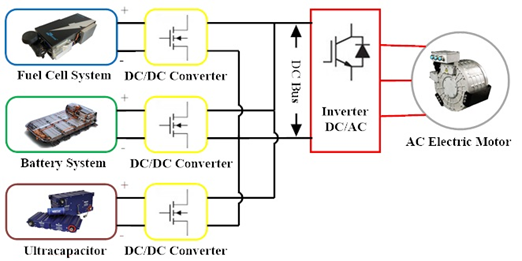
Figure 2. Configuration of a fuel cell hybrid electric vehicle (Topology T5).
Table 1. Summary description of FCEV’s and Fuel Cell Hybrid Electric Vehicle (FCHEV’s) topologies.
|
Topology |
Component Type |
EMS Controller |
Application |
Advantages |
Disadvantages |
Reference |
|
T1 |
PEFC (H2/O2)/Battery PEFC (H2/Air)/Battery |
PI Controller |
Electric-powertrains Aircraft applications |
|
|
[32,33] |
|
T2 |
PEMFC/Battery |
State machine model Switching control method Pontryagin’s minimum principle and dynamic programming Hierarchical reinforcement learning (HRL) |
Plug-in EV FCEV |
|
|
[34–38] |
|
T3 |
PEMFC/Battery/Ultracapacitor |
PI controller |
FCEV |
|
|
[39–41] |
|
T4 |
PEMFC/Battery |
Direct torque control strategy (DTC) Power control strategy and PWM control Neural networks control |
FCEV |
|
|
[42–44] |
|
T5 |
PEMFC/Battery/Ultracapacitor |
Energetic macroscopic representation (EMR) Sliding mode control (SMC) Power control strategy and PWM control Fuzzy logic controllers |
FCHEV |
|
|
[45–48] |
2.3. Current Status of Fuel Cell Technologies in the Automotive Industry
The green energy provided by the fuel cells offers a competitive perspective on the automotive industry market, being the ideal alternative to Internal Combustion (IC) engines [49]. Currently, in the category of green energy, BEVs have the advantage of lower manufacturing costs than FCEVs both in the segment of the small and the middle classes [50]. Thus, by 2030 the light duty vehicle market of fuel cell electric vehicles looks very promising, representing half of the existing competitive segments [51].
Over time, different car manufacturers from different countries have approached the development of FCEVs as follows [52]: Germany in Europe, Japan, Korea and China in Asia and the USA in North America (see Figure 2). F. Liu et al. [53] also presenting in their work a classification of FCEV models from the 2000s to the 2020s. Although 15 countries have public stations for hydrogen fueling of vehicles [54], Toyota Mirai and Hyundai ix35 are available on a larger scale, in the USA currently operating 5600 FCEVs [55] out of a total of 13,600 units globally [56]. However, according to public data in China, the FCEV stock is expected to reach 5000 in 2020s, 50,000 in 2025s and 1 million in 2030s [57]. At the same time, Japan and California have made similar pronouncements in the ambitious goals of achieving FCEVs. Japan is targeting 20,000 vehicles by 2025s and 800,000 by 2030s, and in California by 2023s, 37,400 FCEVs will enter the market and 1 million by 2030s as in China [58]. The most ambitious target is South Korea (the country of origin of Hyundai-Kia) and Germany with a total of 1.8 million FCEVs by 2030s [59,60].
The development and commercialization of the fuel cell electric vehicles is in full expansion, as previously presented. If on the Asian market in 2020 Hyundai introduced the new NEXO model, with an estimated driving range of 380 miles (approximately 611 km) [61], BMW (Munich, Germany), developed a SUV concept for future models in the upper segments of the X family: BMW i Hydrogen NEXT Concept Car [62]. The main challenges faced by the automotive industry’s developers for improving FCEVs and increasing sales volumes globally are durability and cost [63]. In terms of durability, the catalyst in the PEMFC system is the most affected, constantly seeking solutions to improve electrochemical performance, structure and morphology [64]. Advanced technologies for electrocatalysis have been developed in [65] based on the two-dimensional nanomaterials. At the same time, another system that influences the durability of an FCEV is the battery system being the most disposed to aging, with a maximum lifespan of 10 years, the main sources affecting the battery being local climate, overheating and high discharging/charging rates [66].
According to the US department of energy of 2020s FCS they cost US $40/KW with an efficiency of 65% at peak power [67]. The highest cost of the FCS assembly is represented by the catalyst with a percentage of 41% of the total cost, this being caused by the material used, namely the platinum base (Pt-based) [68]. Thus, the developers challenges regarding the catalyst have both durability and cost.
Other factors that would significantly reduce the final costs of a fuel cell electric vehicle would be the automation of the production of the component subassemblies at a competitive cost in the market and the implementation of the necessary infrastructure in many more countries of the world [69]. In our opinion the main difficulties in implementing these topologies on real vehicles, preventing the adoption of FC technologies as automotive propulsion systems are as follows:
- Low flexibility in power flow control in PEMFC + B configuration;
- The PEMFC + B + UC topology suffers from substantial losses of power flow, which makes the control of energy systems complex;
- Batteries have a low power density which leads to an increase in the size of the battery system involving substantial production costs and a much higher mass of the vehicle.
This entry is adapted from the peer-reviewed paper 10.3390/en14010252