Diamond-like carbon (DLC) films have been extensively applied in industries owing to their excellent characteristics such as high hardness. In particular, there is a growing demand for their use as protective films for mechanical parts owing to their excellent wear resistance and low friction coefficient. DLC films have been deposited by various methods and many deviate from the DLC regions present in the ternary diagrams proposed for sp3 covalent carbon, sp2 covalent carbon, and hydrogen. Consequently, redefining the DLC region on ternary diagrams using DLC coatings for mechanical and electrical components is urgently required. Therefore, we investigate the sp3 ratio, hydrogen content, and other properties of 74 types of amorphous carbon films and present the classification of amorphous carbon films, including DLC. We measured the sp3 ratios and hydrogen content using near-edge X-ray absorption fine structure and Rutherford backscattering-elastic recoil detection analysis under unified conditions. Amorphous carbon films were widely found with nonuniform distribution. The number of carbon atoms in the sp3 covalent carbon without bonding with hydrogen and the logarithm of the hydrogen content were inversely proportional. Further, we elucidated the DLC regions on the ternary diagram, classified the amorphous carbon films, and summarized the characteristics and applications of each type of DLC.
- carbon
- diamond-like carbon
- classification
- sp3 hybridization
- sp2 hybridization
1. Introduction
Diamond-like carbon (DLC) films are a kind of amorphous carbon film, wherein both the σ and π bonds due to sp3 and sp2 hybrid orbitals constituting diamond and graphite, respectively, are the carbon skeletons [1,2,3,4]. Aisenberg and Chabot conducted a series of experiments to fabricate diamond films using a carbon ion beam and confirmed the formation of diamond-like amorphous carbon films, known as diamond-like carbon. This marked the beginning of DLC research [5].
DLC films feature high hardness, high wear resistance, low friction coefficient, high insulation, high chemical stability, high gas barrier properties, high anti-burning properties, high biocompatibility, and high infrared permeability. DLC films with flat surfaces can be synthesized at low temperature (~200 °C). Hence, they have a wide range of applications [6,7,8], such as electric and electronic equipment (e.g., hard disks, video tapes, integrated circuits), cutting tools (e.g., drills, end mills, razors), molds (e.g., optical parts, injection molding), automotive parts (e.g., piston rings, cam-related parts, clutch plates, pumps, injectors), optical components (e.g., lenses), plastic bottle oxygen barrier films, sanitary equipment (faucets), windows, bathtub mirrors, and decorative items. Their demand as protective films for automotive parts is rapidly increasing, particularly due to their excellent wear resistance and low friction coefficient properties [9].
The ratio of sp3 to sp2 binding in DLC ranges from ~10% to ~90%. Moreover, the hydrogen content in DLC varies from 0 to 50 at%. Robertson et al. proposed a ternary diagram [10] of sp3 carbon, sp2 carbon, and hydrogen targeting DLC films with large chemical bonding and compositional variations, which provides the understanding of DLC existence regions in the sp3 bond, sp2 bond, and hydrogen content axes. The diagram was constructed using 28 sets of experimental data referenced by Robertson et al. All the samples were evaluated by nuclear magnetic resonance (NMR) and elastic recoil detection analysis (ERDA). Jacob et al. proposed a fully constrained network model [11,12] on this ternary diagram to demonstrate the degree of clustering of the sp2 phase shown as a region. Furthermore, the DLC film is classified based on the sp3 ratio and hydrogen content cited by 19 studies [13]. Bewilogua et al. [14] and Reinke et al. [15] strengthened the diagrams by adding experimental data on the sp3 ratio of hydrogenated amorphous carbon films obtained from Fourier-transform infrared spectroscopy (FTIR) spectra and confirmed that hydrocarbon films can be classified into two types, regardless of the production method. Zhang et al. created a ternary diagram comprising nanocrystalline graphite, a fused aromatic ring, and olefinic chain clusters from a survey of the Raman spectra of many DLC films; further, they classified DLC primarily based on the morphology characterized by the presence of sp2 carbons [16].
To date, Vetter investigated and detailed the addition of various additives (e.g., Si, F, B, Ti, Al, Mo, Co, Fe, Ni, Cu, W, Zr, Ag, Au, H, and N) in DLC films. Notably, the static contact angle of a water droplet and electric properties of DLC vary significantly, depending on the type and concentration of the third element added [17]. The film structure forms a mixing layer, which lowers the sp3 ratio near the substrate or forms an intermediate layer. The amorphization trajectory of the sp2 phase clustering, which ranges from crystalline graphite to amorphous carbon, has been explained by a model that changes from nanocrystalline graphite with a cluster size of ≥2 nm to a fused aromatic ring of ≤2 nm and further converts it into olefin-chain nanoclusters [18,19]. The hydrogen content in DLC films significantly impacts both the hardness and friction coefficient. Furthermore, the friction coefficient of DLC films grown using raw material gas with a very high hydrogen/carbon ratio (e.g., 10) is typically very low (μ = 0.003), whereas that of DLC films without hydrogen is very high (μ = 0.65) [20].
Amorphous carbon films containing DLC films are synthesized by various methods such as chemical vapor deposition (CVD), which includes plasma-enhanced CVD [21,22,23,24,25,26,27,28,29], electron cyclotron resonance (ECR) plasma CVD [30], plasma-based ion implantation and deposition (PBII&D) [31,32], and physical vapor deposition, which includes ionized evaporation [33], sputtering [34,35], unbalanced magnetron sputtering (UBMS) [36,37], ECR sputtering [38,39], high-power impulse magnetron sputtering (HiPIMS) [40,41], filtered cathodic vacuum arc (FCVA) [42,43,44,45], ion-beam deposition (IBD) [5,46,47,48], arc ion plating (AIP) [49,50], pulsed laser deposition (PLD) [51], and laser arc deposition [52,53]. Many of the DLC films produced by these methods have deviated from the DLC regions on the ternary diagrams reported to date. Therefore, redefining the DLC region on the ternary diagram, which uses DLC coatings for mechanical and electrical components, is urgently required in academia and industries. In fact, Germany made a national effort to standardize the carbon films and published the German standard VDI2840 in 2005 [54].
Therefore, in this study, 74 types of amorphous carbon films were collected, and the sp3 ratios and hydrogen contents of the films were evaluated. Importantly, the properties of the amorphous carbon films were each evaluated using a single near-edge X-ray absorption fine structure (NEXAFS) for the sp3 ratio analysis, a single 13C NMR for the sp3 ratio analysis, and a single Rutherford backscattering spectroscopy-ERDA (RBS-ERDA) for the hydrogen content analysis, to eliminate errors due to differences in the equipment and measurement conditions. The DLC regions were clarified on the ternary diagram based on the measured data. Subsequently, the amorphous carbon films containing DLC were classified.
The effects of sp3 ratio and hydrogen content on various properties of amorphous carbon were clarified by comparing and investigating the results of the sp3 ratio and hydrogen content obtained by RBS-ERDA with those of the density, refractive index, extinction coefficient, nano-indentation hardness, visible light Raman spectrum, ultraviolet light Raman spectrum, static water-drop contact angle, and corrosion properties (Section 3). Finally, the type of DLC film and its application fields were described based on the classification results and characteristic evaluation of amorphous carbon films.
2. DLC Characteristics and Applications
Figure 11 summarizes the classification of amorphous carbon films by making the plots on a ternary diagram. Although this classification was similar to that summarized by Robertson et al. [10] , a clearer classification using data from 74 types of amorphous carbon analyzed in a single series by the same analyzer was achieved. In general, ta-C films are presumably free of hydrogen or have minimal amounts because, by definition, the tetrahedral structure predominantly contains σ bonds. Therefore, ta-C was considered the region where the sp3 ratio exceeded 50% and the hydrogen content was <~5 at%. Further, a-C was classified as the region where the sp3 ratio and hydrogen content were ≤50% and ≤5 at%, respectively. Figure 10 also depicts a clear separation between ta-C and a-C in terms of the nano-indentation hardness. The large region with an sp3 ratio and hydrogen content of <50% and >5 at%, respectively, was labeled as a-C:H if a large amount of hydrogen was introduced into a-C. Regions where hydrogen was introduced into ta-C could be expressed as ta-C:H in a manner similar to that of a-C:H. These four regions are all DLC, which may be classified as polymer-like carbon films in the cases where the hydrogen content is high (>~40 at%) and a linear chain structure is dominant. These films also exhibit small hardness values. However, there are also films with hardness values >9 GPa, even when the hydrogen contents exceed 40 at%. These films did not adopt a linear structure and were considered as a-C:H or ta-C:H.
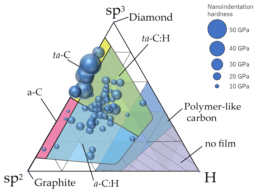
Figure 11. Distribution of 74 types of amorphous carbon films on the ternary diagram. The diameter of the circle corresponds to the nanoindentation hardness of each amorphous carbon film.
Interestingly, a gap (5–20 at%) existed where the hydrogen content was not uniformly distributed. Hence, there are very few films with hydrogen contents of 5–20%. Tetrahedral structures with sp3 bonds as the skeleton were stabilized without hydrogen, adopting a structure with an a-C:H ratio of 3–4:1 when hydrogen is introduced into the DLC. However, it is difficult to distinctly determine this structure as the hydrogen content in the sp3 and sp2 domains are expected to differ [94,95].
Table 4 summarizes the characteristics of amorphous carbon films and its applications by associating the results obtained in this study with the classifications described in Section 4. ta-C is used for various components including mechanical parts, automotive parts, machining tools, cutting tools, metal molds, hard disk heads, infrared transmission protective films, low-dielectric-constant materials, and insulating materials due to its high hardness. ta-C:H is used for various components such as mechanical parts, automotive parts, metal molds, hard disks, magnetic tapes, optical element coatings, and scissors owing to its relatively high hardness and low friction coefficient. a-C is used for components such as optical element coating; and a-C:H is used for components such as mechanical parts, biomedical material coating, sealing materials, gas barrier coating, low-dielectric-constant materials, and insulating materials. PLC is exclusively utilized for gas barrier coatings.
Table 4. Classification of amorphous carbon films including DLC films, and those with industrial applications.
| Classification | DLC | DLC | DLC | DLC | not DLC |
|---|---|---|---|---|---|
| Short name | ta-C | ta-C:H | a-C | a-C:H | PLC |
| Designation | Tetrahedral hydrogen-free amorphous carbon film | Tetrahedral hydrogenated amorphous carbon film | Hydrogen-free amorphous carbon film | Hydrogenated amorphous carbon film | Polymer-like carbon |
| sp3/(sp3 + sp2) (%) | 50–90 | 50–90 | 10–50 | 10–50 | - |
| H (at%) | <5 | 5–50 | <5 | 5–50 | 40–70 |
| Deposition method | PVD | PVD, CVD, PVD + CVD | PVD | CVD, PVD + CVD | CVD, PVD |
| Deposition temperature (°C) | RT-300 | RT-500 | RT-200 | RT-500 | RT-100 |
| True density ρ (g/cm3) (as reference) | 3.5 > ρ > 2.6 | 2.6 > ρ > 2.0 | 1.7 > ρ > 1.4 | 2.0 > ρ > 1.4 | ρ < 1.4 |
| Coefficient of friction vs. steel (dry cond.) (as reference) | 0.1–0.2 | 0.08–0.2 | 0.1–0.2 | 0.08–0.2 | Unstable |
| Wear resistance vs. steel (dry cond.) | A | B–A | C | B–A | × |
| Nano-indentation hardness (HIT: GPa) | 25–90 | 9–35 | 9–25 | 9–25 | 0.5–9 |
| Young’s modulus (GPa) | 200–900 | 120–300 | 100–400 | 100–220 | ~100 |
| Corrosion resistance | B–A | C–B | ×–C | B | B |
| Water contact angle (°) (as reference) | 70–80 | 80–100 | 70–100 | 70–90 | ~70 |
| Refractive index n (λ = 550 nm) | 2.5–3.0 | 2.0–2.5 | 1.8–2.5 | 1.7–2.4 | 1.5–2.0 |
| Extinction coefficient k (λ = 550 nm) | 0.04–0.5 | 0.05–0.6 | 0.1–0.6 | 0.05–0.6 | ~0.1 |
| Color (500 nm in thick) |
Transparent (Interference color) |
Brown | Black | Light brown | Transparent |
| Optical band gap (eV) | 0.2–1.7 | 1.0–2.5 | 1.0–1.7 | 0.5–2.0 | NA |
A: Excellent; B: Good; C: Somewhat poor; ×: Poor; NA: Unknown.
This entry is adapted from the peer-reviewed paper 10.3390/ma14020315