As a new “sink” of CO2 permanent storage, the depleted shale reservoir is very promising compared to the deep saline aquifer. To provide a greater understanding of the benefits of CO2 storage in a shale reservoir, a comparative study is conducted by establishing the full-mechanism model, including the hydrodynamic trapping, adsorption trapping, residual trapping, solubility trapping as well as the mineral trapping corresponding to the typical shale and deep saline aquifer parameters from the Ordos basin in China. The results show that CO2 storage in the depleted shale reservoir has merits in storage safety by trapping more CO2 in stable immobile phase due to adsorption and having gentler and ephemeral pressure perturbation responding to CO2 injection. The effect of various CO2 injection schemes, namely the high-speed continuous injection, low-speed continuous injection, huff-n-puff injection and water alternative injection, on the phase transformation of CO2 in a shale reservoir and CO2-injection-induced perturbations in formation pressure are also examined. With the aim of increasing the fraction of immobile CO2 while maintaining a safe pressure-perturbation, it is shown that an intermittent injection procedure with multiple slugs of huff-n-puff injection can be employed and within the allowable range of pressure increase, and the CO2 injection rate can be maximized to increase the CO2 storage capacity and security in shale reservoir.
- CO2 geological storage
- shale
- phase transformation
- pressure perturbation
- injection schemes
1. Introduction
The capture of anthropogenic carbon dioxide (CO2) from industrial or other emission sources and its long-term storage in geological formations to limit its emission into the atmosphere is referred as geological carbon storage (GCS) [1]. GCS is regarded as one of the most effective technologies to reduce the greenhouse gas emissions from the combustion of fossil fuels. Besides the conventional CO2 storage sites in the deep saline aquifers, depleted oil and gas reservoirs, and un-minable coal seams [2][3], the depleted shale reservoir is also rapidly becoming a new and potentially promising CO2 storage option because of the booming production of the unconventional shale gas [4][5].
Interest in CO2 storage in shale reservoirs has grown recently because shale is widely reported to possess higher affinity to CO2 than CH4 and has huge potential for CO2 adsorption trapping. For example, Heller and Zoback [6], Kang et al. [7], and Zhang [8] all tested the CO2/CH4 adsorption capacity of shale from different places in the world and demonstrated that the CO2 adsorption capacity to shale was greater than that of CH4 under surface condition. Several feasibility studies for CO2 storage in shale reservoirs have demonstrated that CO2 can be trapped in the shale matrix and at the same time can significantly enhance the methane recovery by CO2/CH4 competitive adsorption [9]. Liu et al. [10] indicated that 95% of injected CO2 can be permanently sequestered in the Devonian and Mississippian New Albany shale with gas adsorption being the dominant storage mechanism. A large storage capacity of CO2 in shale reservoirs has also been evaluated and it was estimated that the CO2 storage capacity of the Marcellus shale in the eastern United States alone could store between 10.4 and 18.4 Gt of CO2 between now and 2030 [11].
In GCS, it is very important to study the CO2 plume evolution and migration as well as different phase transformations due to various trapping mechanisms for the sake of security. In a shale reservoir, there is one more trapping mechanism for CO2 compared to those in the deep saline aquifers, and that is the adsorption trapping of CO2 to the surface of the host rock simultaneously promoting the desorption of the in-place CH4 [12]. It is important to recall here the other well-known trapping mechanisms, namely the hydrodynamic trapping, solution trapping, mineral trapping and residual or capillary trapping. Furthermore, although all these trapping mechanisms may take effect within a given reservoir, they occur at different time scales. Moreover, only a few of these mechanisms contribute significantly to plume immobilization in time scales comparable to the injection times or arguably even over the duration of the site stewardship. On shorter time scales, hydrodynamic trapping, residual, and adsorption trapping are the dominant mechanisms that play an important role in plume immobilization in the reservoir [13][14][15][16]. In the long-term, a significant amount of CO2 will be trapped through dissolving into the formation water (solubility trapping) and finally being permanently stored in mineral phase by reacting with the host rock (mineral trapping), which gradually begins to contribute to CO2 plume immobilization in shale reservoirs [12].
2. Results and Discussion
Table 1 shows the simulation cases considered and analyzed in this paper.
Table 1 Description of simulation cases
|
Case description |
Gas adsorption |
CO2 injection rate/(m3/day)* |
CO2 injection period /(year) |
CO2 injection scheme |
Lithology |
|
Case 1 |
/ |
4000 |
30 |
Continuous injection |
LJG sand |
|
Case 2 |
R |
4000 |
30 |
Continuous injection |
YC shale |
|
Case 3 |
R |
2000 |
60 |
Continuous injection |
YC shale |
|
Case 4 |
R |
4000 |
30 |
Huff-n-puff injection |
YC shale |
|
Case 5 |
R |
4000 |
30 |
Water alternating gas injection |
YC shale |
* 4000 m3/day ≈ 0.09 kg/s
2.1. Comparison of CO2 Storage in Shale and Deep Saline Aquifer
The cumulative levels of CO2 trapped with different mechanisms for the Yanchang (YC) shale and Liujiagou (LJG) sand from Shenhua saline aquifer in Ordos basin in China at the same CO2 injection rate are compared and plotted in Figure 1. It can be observed that with a total amount of 1861.55 Mmoles (1861.55 × 106 moles) of CO2 injected in 30 years, 656.59 Mmoles was in the free phase, 474.66 Mmoles was adsorbed, 102.03 Mmoles was trapped in residual phase, 179.12 Mmoles was dissolved in the formation water, and the remaining 458.06 Mmoles was trapped as mineralized CO2 in shale at 500 years. For sand, 1075.36 Mmoles was in the free phase, 279.44 Mmoles was trapped through hysteresis, 155.88 Mmoles was in dissolution phase, and the rest 353.82 Mmoles was stored through CO2–water–shale reactions. Within a timescale of <200 years, sand reservoir possesses priority in trapping CO2 not only in the free gas phase and residual phase but also in the dissolution phase as well as the mineral phase. As time goes on, the superiority of sand trapping of CO2 in the stable chemical phase is overwhelmed by shale.
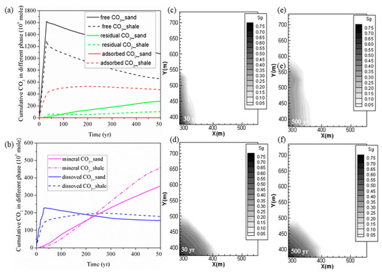
Figure 1. (a,b) Cumulative CO2 storage under different mechanisms in shale and sand; (c,e) free CO2 distributions for case 1 (YC shale) at 30 years and 500 years; (d,f) free CO2 distributions for case 2 (LJG sand) at 30 years and 500 years.
Figure 1 also displays the CO2 plume distribution at 30 years and 500 years for the sand and shale reservoir. Due to the high permeability of LJG sand compared to the YC shale, both CO2 and pressure migrate faster along the horizontal plane, and this phenomenon is discussed in detail later. However, the pressure perturbation induced by CO2 injection in the shale reservoir was constrained close to the stimulation zone. Once injection stopped, the in-place groundwater invaded the gas in the pores and micro-fractures and created the accumulation of CO2 in residual phase. The larger CO2 plume in the sand reservoir increases the interfacial area for subsequent residual trapping, dissolution and even the reaction with minerals (Figure 1(a, b)).
Although both reservoirs experience a pressure reduction response to injection stoppage, the pressure variation is neglected within the CO2 plume for the sand reservoir and the fluid flow is dominated by diffusion in horizontal plane. However, there is nearly a 17-MPa pressure difference between the injection site and the margin of the CO2 plume in shale; both advection and diffusion control the CO2 migration. As a result, the CO2 plume still expands outward for the shale but remains nearly unchanged for the saline aquifer after injection stops. It leads to wider CO2 plume at 500 years for shale than for the sand reservoir. The pressure perturbation caused by CO2 plume evolution combined with the transformation of the adsorbed phase into the dissolved phase causes the phenomenon of shale having more chemical trapping of CO2 in the longer term.
The various CO2 storage mechanisms have different operating time frames, among which the hydrodynamic and adsorption trapping take effect immediately after the CO2 injection, while the residual gas, dissolution and particularly the mineral trapping mechanisms are a slow process, and can occur over a time scale of centuries to millennia. Instead, these three mechanisms play an essential role in increasing the security and safety of CO2 geological storage [3]. In addition, different trapping mechanisms are strongly coupled and are competitive with each other, and different phases of CO2 in the reservoir inter-convert dynamically. To improve CO2 storage security as well as efficiency, the CO2 injection strategy should be optimized based on the idea of expanding CO2 plume and decrease in the percentage of CO2 in the free gaseous phase.
2.2. Effect of CO2 Injection Rate on CO2 Storage in Shale
As stated previously, to enhance the CO2 storage security in a shale reservoir by constraining the capacity of free and mobile-phase CO2 and to maintain a relatively gentle pressure perturbation, the CO2 injection strategy should be precisely designed and optimized. The effects of the CO2 injection rate on the overall performance of the sequestration project are investigated first. We do so by comparing case 2 and case 3. The same amount of CO2 is injected in both cases, but over a period of 30 years in case 2 and over a period of 60 years in case 3.
The cumulative CO2 in different phases for both cases (case 2 and case 3) is shown in Figure 2(a,b). By comparing the deviation of the cumulative CO2 stored in different phases for case 2 and case 3 at 500 years shown in Table 2, the change in residual trapping is most dramatic with the change in the injection rate. It can be seen from Table 2 that there was a 19.52% reduction in the residual trapping of CO2 due to a decrease in the CO2 injection rate. In addition, case 3 also has more CO2 in the mobile free phase than case 2; the deviation is 38.56 Mmoles at 500 years. More CO2 exists in the free phase to promote its horizontal migration. This result is also supported by the profile of the gas saturation in the fractures of the shale reservoir as shown in Figure 2(c–h). This profile clearly shows that the free-phase CO2 migrates further horizontally at higher CO2 injection rate especially during the period of CO2 injection.
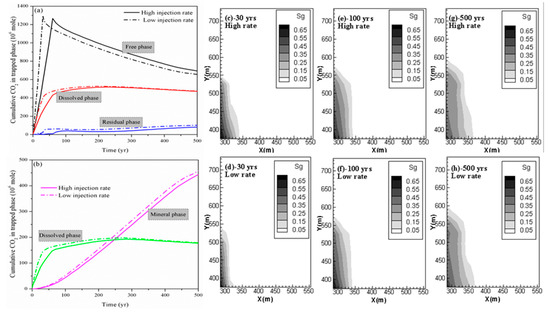
Figure 2. (a,b) Cumulative CO2 storage under different mechanisms at different CO2 injection rates; (c,e,g) free CO2 distributions for case 2 at 30 years, 100 years and 500 years; and (d,f,h) free CO2 distributions for case 3 at 30 years, 100 years and 500 years.
Table 2. Comparison of CO2 amount in different phases for case 2 and case 3.
|
|
Cumulative CO2 Trapped under Different Mechanisms/(106 moles) |
||||
|
Case |
Hydrodynamic Trapping |
Adsorbed Trapping |
Residual Trapping |
Dissolution Trapping |
Mineral Trapping |
|
Case2 |
656.59 |
474.66 |
102.03 |
179.12 |
458.06 |
|
Case3 |
695.15 |
472.18 |
82.11 |
177.39 |
443.53 |
|
Deviation |
5.87% |
−0.52% |
−19.52% |
−0.97% |
3.17% |
2.3. Effect of Huff-N-Puff Injection and Water Alternating Gas Injection
Finally, we investigate the performance of the CO2 sequestration project using the huff-n-puff injection scheme and the injection of alternating slugs of water and CO2 scheme, which are widely used in the oil/gas industry to enhance oil and gas production. We compare the results of case 2, case 4 and case 5. In all the three cases, CO2 is injected at a rate of 4000 m3/day over a period of 30 years. In case 2, the injection of CO2 is continuous. In case 4, CO2 is first injected for 15 years, then the well is shut-down and soaked for five years, and finally the well is opened again and injected for another 15 years. In case 5, the injection scheme is as follows: CO2 is first injected at a rate of 4000 m3/day for 15 years, water is then injected at a rate of 50 m3/day for 5 years, and finally the CO2 is injected at the rate of 4000 m3/day for another 15 years.
As shown in Figure 3, for the huff-n-puff injection scheme, the addition of CO2 soaking time has a limited impact on the performance of CO2 storage in a shale reservoir compared to the continuous injection, especially for long-term CO2 storage. However, at the beginning, the amount of free CO2 increases while the immobile CO2 in residual as well as the dissolved phase decreases for the huff-n-puff injection scheme, which is not beneficial for the storage safety of CO2. On the other hand, the water alternating gas injection scheme can somehow reduce the free-phase CO2 as well as the adsorbed-phase CO2 by enhancing the CO2 dissolution into the formation water and trapping it in the micro-pores in the residual phase within the timescale of 300 years. However, with the continual ex-solution of CO2 from formation water in the longer term, the CO2 reaction with the host rock is also prohibited.
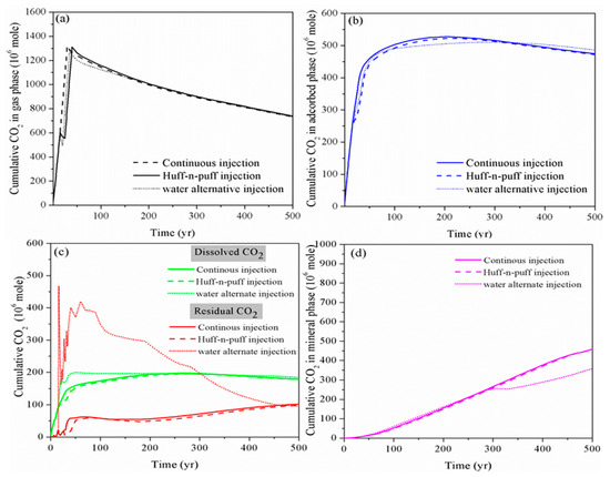
Figure 3. Cumulative CO2 storage in different storage mechanisms using various CO2 injection schemes. (a): gas phase;(b): adsorbed phase; (c): dissolved and residual phase; (d): mineral phase)
Figure 4 shows the free-phase CO2 distributions for case 2, case 4 and case 5 at 30 years, 100 years and 500 years. It can be observed that, for case 2 and case 4, although the addition of soaking time for CO2 injection can hinder the gaseous CO2 migration in the horizontal direction, once injection stops, the migration rate is accelerated and the mobile CO2 can even move faster than in the case of the continuous injection scheme. The gaseous CO2 front in Y direction at 500 years arrives at 600 m for the huff-n-puff scenario but only at nearly 580 m for the continuous injection scenario. On the other hand, the water alternating gas injection scheme (case 5) can apparently decrease the capacity of mobile CO2 during the whole period of CO2 storage.
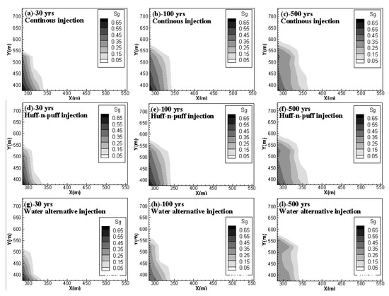
Figure 4. Free CO2 distributions for case 2, case 4 and case 5 at 30, 100 and 500 years. (a,b,c) compare the gas phase CO2 distribution of continuous injection scenario at 30 yrs, 100 yrs and 500 yrs, respectively; (d,e,f) show the gas phase CO2 distribution of huff-n-puff injection scenario at 30 yrs, 100 yrs and 500 yrs; (g,h,i) give gas phase CO2 distribution of water alternative injection scenario at 30 yrs, 100 yrs and 500 yrs.).
2.4. Pressure Perturbation Induced by CO2 Injection
The performance of CO2 storage in the subsurface is highly dependent on the pressure evolution in the formation. The adsorptive behavior of gas onto an organic substrate is largely dependent on pressure. Although there are different types of adsorption models that can be used to describe the CO2 adsorptive behavior to shale, for example the Langmuir model used for the New Albany shale [17] and the Devonian shale from the Kentucky [5], and the BET-type adsorption of CO2 onto Barnett shale [18], they all show that the CO2 adsorption capacity is a function of ambient pressure. The CO2 dissolution into the formation water is also largely impacted by pressure. Xu et al. [19] indicate that the pressure variation in the reservoir can affect the dissolution of CO2 into the formation brine. As the volume of dissolved CO2 changes, the original chemical equilibrium between CO2 (aq.), H2CO3, and HCO3− can be re-established and the mineral reactions will also change accordingly.
Furthermore, pressure variation is also a cause for the change in residual trapping. The non-wetting gas to invade the smaller pores is driven by the higher formation pressure, and the snap-off also results in the increase in macroscopic trapping that occurs readily in smaller pores during imbibition. On the other hand, the gravity effect impacts the displacement pattern of water by CO2 for low capillary entry pressure. Compared with high-viscosity fluid, the low-viscosity gas can form more stable paths when penetrating the high permeability regions of the porous medium, and only the largest pores can be invaded to lead to reduced snap-off during an eventual imbibition process [15].
Figure 5 shows the pressure variation at observation point #1 (X = 275 m, Y = 375 m), which is located at the injection site for case 1, case 2, case 3, case 4 and case 5. The drastic pressure build-up induced by CO2 injection in the LJG sand is larger and more lasting compared with the YC shale, which displayed with a rapid speed of pressure up and down (Figure 5a). The higher permeability not only enhances the fluid penetration into the rock pores and fractures, but also increases the pressure transmission through the reservoir. The pressure perturbation was constrained within the stimulation zone for the shale reservoir; however, the pressure variation was extended to the whole simulation domain for the sand cases and decreased very slowly responding to the injection well shut-in. The significant pressure deviation between the injection site and the surrounding area was the cause of CO2 plume expansion within the shale reservoir and also increased the interfacial area for subsequent CO2 dissolution and mineral trapping.
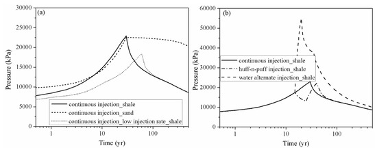
Figure 5. Pressure evolution at observation point # 1 (X = 275 m, Y = 375 m) for different cases. (a) compares the pressure perturbation of continuous injection scenario of shale and sand and also the influence of injection rate; (b) shows the pressure build-up of continuous injection scenario, huff-n-puff injection scenario and water alternate injection scenario of shale reservoir).
The pressure build-up in case 3 at the injection point is smaller than in case 2, which significantly weakens the residual trapping, as shown in Table 2. The pressure decrease also leads to the release of CO2 from the formation water, which combined with gas desorption causes more CO2 to exist in the free phase. Considering pressure perturbation induced by the three CO2 injection schemes (as shown in Figure 5b), although the water alternating gas injection scheme can increase the CO2 storage security in a shale reservoir by trapping more CO2 in the immobile phase, it induces large pressure build-up during water injection.
2.5. Implication to CO2 Storage Safety and Stability
Due to the high diffusivity of gaseous or supercritical CO2, the free-phase CO2 is generally believed to be in the unstable phase, which can easily migrate into the preferential pathways such as natural or artificial fracture, unfolded fault and abandoned wells and leak from the storage site. Bachu et al. [3] state that the residual-gas trapping, dissolution, and mineralization of CO2 are essential mechanisms in increasing the security and safety of geological storage of CO2 in a saline aquifer after cessation of injection as less and less CO2 remains in the free, mobile phase over time. It is similar for CO2 storage in a shale reservoir. Figure 6 compares the CO2 storage security evolution with time for LJG sand and YC shale. It can be seen that the CO2 storage security increases with time both for shale and sand because more and more CO2 gets stored as a trapped phase over time. Although LJG sand possesses the advantage in trapping more CO2 in the residual, dissolution as well as mineral phase in the short term, this merit is overwhelmed by YC shale as time goes on. Besides, more than 20% of gaseous CO2 is trapped in the adsorbed phase; the overall unstable mobile-phase CO2 in the YC shale reservoir is significantly less than the LJG sand, which indicates that shale shows superiority in security of CO2 storage over saline aquifer.
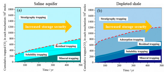
Figure 6. Storage security of CO2 in (a) a deep saline aquifer and (b) in a depleted shale reservoir.
3. Conclusions
This study presents a comprehensive analysis of the potential of CO2 storage in a shale reservoir based on the geological parameters of Yang Chang (YC) shale in the Ordos basin of China by taking into account the Darcy and diffusive flow, gas sorption/desorption, hysteresis effects, CO2 dissolution, and CO2–water–shale reactions. The advantage and disadvantage of CO2 storage in YC shale are analyzed by comparing them with the CO2 storage in LJG sand (saline aquifer) from the Shenhua GCS project in China. To enhance CO2 storage security in shale by constraining the capacity of free and mobile-phase CO2 and to maintain a relatively gentle pressure perturbation, different injection strategies, including the low rate continuous injection, high rate continuous injection, huff-n-puff injection and the water alternate injection are compared. The results can be summarized as follows:
-
From the point of view of CO2 phase transformation, CO2 storage in shale can be safer than in saline aquifer by trapping more CO2 in immobile phases, including adsorbed, residual, dissolution and mineral phase with lesser percentage remaining in free mobile phase in longer-term. Although, the saline aquifer has the advantage in trapping more CO2 in the residual, dissolution and mineral phase in the short term.
-
The pressure perturbation induced by CO2 injection in the saline aquifer is longer lasting and generally larger than in the shale reservoir. The pressure build-up in shale can be rapidly released when CO2 injection is stopped.
-
Although the water alternating injection scheme can significantly increase the dissolution and residual phase of CO2 in short to middle term, the pressure build-up caused by water injection is more drastic than other schemes. For the aim of increasing the fraction of immobile CO2 while maintaining a safe pressure-perturbation, the intermittent injection procedure with multiple slugs of huff-n-puff injection can be employed to replace the continuous CO2 injection. Within the allowable range of pressure increase, the CO2 injection rate can be maximized to increase the CO2 storage capacity and security in a shale reservoir.
This entry is adapted from the peer-reviewed paper 10.3390/en13133397
References
- Bachu, S. Sequestration of CO2 in geological media: Criteria and approach for site selection in response to climate change. Energy Convers. Manag. 2000, 41, 953–970.
- Bachu, S.; Adams,J.J. Sequestration of CO2 in geological media in response to climate change: capacity of deep saline aquifers to sequester CO2 in solution. Energy Convers. Manag. 2003, 44(20), 3151-3175.
- Bachu, S.; Bonijoly, D.; Bradshaw, J.; Burruss, R.; Holloway, S.; Christensen, N.; Mathiassen, O.M. CO2 storage capacity estimation: Methodology and gaps. Int. J. Greenh. Gas Control 2007, 1, 430–443.
- Busch, A.; Alles, S.; Gensterblum, Y.; Prinz, D.; Dewhurst, D.N.; Raven, M.D.; Stanjek, H.; Krooss, B.M. Carbon dioxide storage potential of shales. J. Greenh. Gas Control 2008, 2(3), 297–308.
- Nuttal, B.C.; Eble, C.; Bustin, R.M.; Drahovzal, J.A. Analysis of Devonian black shales in kentucky for potential carbon dioxide sequestration and enhanced natural gas production. Gas Control Technol. 2005, 7, 2225–2228.
- Heller, R.; Zoback, M. Adsorption of methane and carbon dioxide on gas shale and pure mineral samples. Unconv. Oil Gas Resour. 2014, 8, 14–24.
- Kang, S.M.; Fathi, E.; Ambrose, R.J.; Akkutlu, I.Y.; Sigal, R.F. Carbon dioxide storage capacity of organic-rich shales. Spe J. 2011, 16, 842–855.
- Zhang, J. Study of Continental Shale Gas Adsorption and Desorption Effect in Fuxian Area of Ordos Basin; Southwest Petroleum University: Chengdu, China,
- Schepers, K.C.; Nuttall, B.; Oudinot, A.Y.; Gonzalez, R. Reservoir Modeling and simulation of the Devonian Gas Shale of Eastern Kentrucky for Enhanced Gas Recovery and CO2 Soc. Pet. Eng. 2009. Doi: https://doi.org/10.2118/126620-MS
- Liu, F.; Ellett, K.; Xiao, Y.; Rupp, J.A. Assessing the feasibility of CO2 storage in the New Albany Shale (Devonian–Mississippian) with potential enhanced gas recovery using reservoir simulation. J. Greenh. Gas Control 2013, 17, 111–126.
- Tao, Z.; Clarens, A. Estimating the carbon sequestration capacity of shale formations using methane production rates. Sci. Technol. 2013, 47, 11318–11325.
- Liu, D.; Li, Y.; Agarwal, R.K. Numerical simulation of long-term storage of CO2 in Yanchang shale reservoir of the Ordos basin in China. Geol. 2016, 440, 288–305.
- Benson, S.; Cook, P.; Anderson, J.; Bachu, S.; Nimir, H.B.; Basu, B. Capter 5—Underground geological storage. In IPCC Special Report on CO2 Capture and Sequestration; Cambridge University Press, New York,
- Hesse, M.A.; Orr, F.M.; Tchelepi, H.A. Gravity currents with residual trapping. Fluid Mech. 2008, 611, 35–60.
- Juanes, R.; Spiteri, E.J.; Orr, F.M.; Blunt, M.J. Impact of relative permeability hysteresis on geological CO2 Water Resour. Res. 2006, 42, 395–397.
- Saadatpoor, E.; Bryant, S.L.; Sepehrnoori, K. New Trapping Mechanism in Carbon Sequestration. Porous Media 2010, 82, 3–17.
- Strapoc, D.; Mastalerz, M.; Schimmelmann, A.; Drobniak, A.; Hasenmueller, N.R. Geochemical constraints on the origin and volume of gas in the New Albany Shale (Devonian–Mississippian), eastern Illinois Basin. AAPG Bull. 2010, 94, 1713–1740.
- Vermylen, J.P. Geomechanical Studies of the Barnett Shale; Stanford University: Stanford, CA, USA, 2011.
- Xu, R.; Rong, L.; Jin, M.; Di, H.; Jiang, P. Effect of mineral dissolution/precipitation and CO2 exsolution on CO2 transport in Geological Carbon Storage. Chem. Res. 2017, 50, 2056–2066.