Traditional rigid robot application in the medical field is limited due to the limited degrees of freedom caused by their material and structure. Inspired by trunk, tentacles, and snakes, continuum robot (CR) could traverse confined space, manipulate objects in complex environment, and conform to curvilinear paths in space. The continuum robot has broad prospect in surgery due to its high dexterity, which can reach circuitous areas of the body and perform precision surgery. Recently, many efforts have been done by researchers to improve the design and actuation methods of continuum robots. Several continuum robots have been applied in clinic surgical interventions and demonstrated superiorities to conventional rigid-link robots.
Thanks for checking. The entry will be online only after your submission,which is free. We will help you layout and link your article at the entry. Hence more scholars and students can benefit from it. (Please remove this note when submitting.)
1. Introduction
With the maturity of robot technology, the application of robots is gradually penetrating from the manufacturing industry to all aspects [
1,
2]. Traditional rigid robots have shown broad prospect in service industry, real estate industry, agriculture and other aspects. In recent years, robots have gradually shown their potential in the medical industry [
3]. Medical robots have brought a new breakthrough for the realization of surgery. However, traditional rigid robots cannot meet the requirements of more precise surgical accuracy due to the limitation of flexibility due to their rigid structure [
4]. Especially when performing the operation of the internal position of the human body, the disadvantages of the rigid robot are particularly obvious. The rigid robot cannot match the flexibility of the human organs, and it is difficult to access the circuitous parts of the human body. The emergence of flexible robots provides a solution of this problem. Flexible robots can be segmented into two categories, including finite-degree-of-freedom robots that are linked by a limited number of discrete joints and infinite-degree-of-freedom robots without joint links showed as elastic members [
5]. The infinite-degree-freedom (infinite-DOF) robots is also called continuum robots (CRs). It was first proposed in the 1960s [
6,
7]. Because of its flexibility in movement brought by the infinite degrees of freedom, researchers have paid increasing attention to it. Many ideas of bio-inspired CRs have been proposed, and the review of continuum robots applied in the medical field has also appeared [
7,
8].
2. Actuation Methods for Continuum Robot
We define the actuation of the robot as the process of converting other forms of energy into the power to make the robot realize certain movements [
20]. Due to its own flexible structural characteristics and infinite DOF, it is significantly different from traditional rigid robots in actuation. The traditional rigid robot mainly relies on the built-in motor and gear system to drive. Such driving method will affect the flexibility CRs. The principle of CR’s actuation should guarantee the stiffness requirements and compliance with the application environment such as the organ tissue while the robot applied to the Surgery or the magnetic fields while Cooperated with MRI under the premise of satisfy the actuation requirements. Common actuation methods for CRs include concentric tube transmission, tendon/cable driven, pneumatic/hydraulic driven, smart material driven and Magnetic actuation.
2.1. Concentric Tube Transmission
Concentric tube robots are typically composed of nested pre-curved tubes and each independent concentric tube has 2-DOF [
88,
89]. Concentric tube robots realize bending and twisting relying on the combined action caused by the relatively independent motion of each tube. Through the mutual movement and rotation of multiple tubes, the overall shape of the robot could be changed to change the spatial posture. When applied in minimally invasive surgery, the semi-rigid structure of the concentric tube robot not only makes it flexible, but also ensures that the motion of the concentric tube in the organ tissue can resist the interference of external forces appropriately [
90,
91]. The great potential of concentric tube robots in medical field has been widely appreciated in recent years. The actuation of the concentric tube robot also depends on the concentric tube structure. The energy source for its movement can be input from external energy equipment such as motor. Of course, it can be driven manually. The most remarkable feature of concentric tube robots’ actuation system is cascaded. A cascaded actuation system can be matched with the concentric tube structure of the robot to realize the hierarchical transmission of the concentric tube robot. It also makes the robots actuation system more compact and miniature [
92,
93]. Morimot [
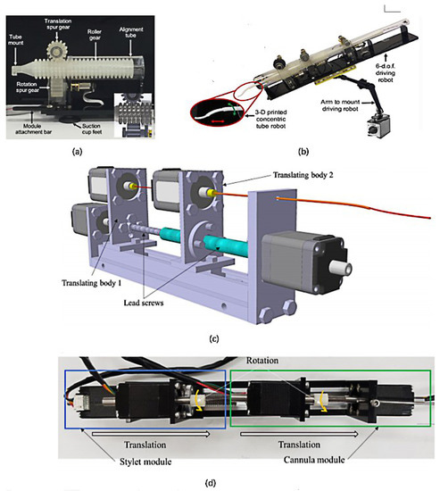
94] and his colleagues at Stanford University used 3D printing to create a three-tube concentric robot with modules separated from each other for surgical operations (b). A drive system composing of a roller gear with teeth in both the axial and radial directions and two spur gears that are perpendicular to each other is integrated in each module. Through the independent coupling motion between the gears in each drive system, the rotation and translation of each module can be realized to meet the demands of different operations.
Figure 12. (
a,
b) Three-tube concentric robot [
94]; (
c) Schematic diagram of the driving system of the concentric tube robot; (
d) Top view of the drive system [
95].
Farooq Muhammad Umai et al. [
95] from Chonnam Natl Univ also designed a nested concentric tube robot based on cascaded actuation modules. They propose a novel actuation system (shown in c) using motors for CTR actuation. The characteristic of the motor compose of a hollow shaft.The tubes’ proximal end will be gripped and the rest of tube pass through the hollow shaft. In this way, the different part of CTR will stay in line to avoid buckling and torsional windup. This nested conical tube robot contains a Stylet module and a Cannula module. This drive system using a total of four motor, of which 2 are used for translation and 2 for rotation. Four motors are used to drive the Stylet Module and the Cannula Module, each with two degrees of freedom.
2.2. Tendon/Cable Driven
The tendon/cable drive was inspired by biology. The robot body is driven by the contraction and stretching of the tendon or cable driven by the motor [
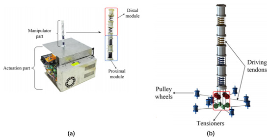
43]. In recent years, the breakthrough in the way of tendon driving is to realize the classification of robot driving. The tendon-driven CRs is usually divided into distal and proximal parts. The distal and proximal control do not affect each other, which can improve the accuracy of robot motion control. Today’s CRs based on tendon driven are typically constructed with tendons embedded in the robot body and a flexible skeleton (usually a spring) at the center. Li, Minhan et al. [
96] proposed a tendon driven, including the manipulator part and actuation part. The movement of the robot will be realized through the cooperation of these two modules. The actuation part composes of a distal module and a proximal module (). Every module composes of two springs, connecting plates and four tendons. The tendons are wound around the eight pulley wheels driven by the independent stepping motors. The pulley wheels and motors are placed in the actuation part. The rotation of the motor will be transformed into the linear motion of the tendon through the pulley wheels. The connecting plates are used to connect the springs and guide the tendons. Because the four tendons in the distal module will pass through the proximal module, eight guide holes in the connector plate are designed to guide the tendons. Used as the center backbone of the robot, springs are able to achieve a linear change in length following the linear force. At the same time, it is possible to use springs to achieve variable stiffness along the robot length o different spring constants. For example, the distal module employs a spring with the lower spring constant (3 N/mm) than the proximal one (5 N/mm). This is the most significant advantage of this drive system, consistent with the design principles of variable stiffness for continuous robots [
63].
Figure 13. (
a) The four parts of the tenon-driven CR are divided into distal and proximal modules; (
b) The tendon is embedded in the body of the robot and is separated from the motor [
96].
2.3. Pneumatic/Hydraulic
Fluid driven is the most common and mature type of actuation for CRs. The traditional fluid driven is to achieve deformation and movement by piping in the fluid such as gas and liquid by making the inner cavity of the CRs contract or expand [
97]. Therefore, an external gas/liquid pump and some fluid pipe are necessary for a fluid driven CRs. Such equipment always possess a large volume, which brings difficulties to the integration of the CRs. At the same time, conventional robots require complex electronic components to achieve control functions, which limits their application areas to a certain extent, such as in flammable environments with high-temperature gases. Conventional gas/liquid actuation have been well developed and there is a lot of paper on them. This part mainly narrate some CRs based on new fluid actuation method that overcomes the defect of traditional gas actuation method.
Pneumatic actuation is widely used in CRs. It can be divided into positive pressure actuation and negative pressure actuation. The positive pressure actuation is to make the cavity expand with the movement and deformation of the flexible actuator by filling the compressed gas into the cavity. Negative pressure actuation refers to the extraction of air from the cavity, which causes the cavity to contract and drives the movement and deformation of the software actuator [
17]. Besides, pneumatic soft systems can require high power-to-weight ratios. A major disadvantage of soft pneumatic robots is that their stiffness cannot vary independently of the position of their end-effector in space. Xiang et al. [
98] presented the novel robot arm successfully decouples its end-effector positioning from its stiffness. The arm combines the high payload to weight ratio, light weight and pneumatic robustness with versatility and adaptability of stiffness modulation. Robertson et al. [
99] presented a single 3-DOF module to set up the baseline performance and characterized attributes of a completely comprehensive hybrid robotic system combining the design methods of pneumatics and origami mechanism as shown in a. Joseph D. Greer [
100] et al. proposed a soft continuum robot based on Series Pneumatic Artificial Muscles (sPAMs) (shown in ). The robot contains 3 axially distributed sPAMs and a tubular pneumatic backbone. SPAMs act as actuator. A sPAM is made from many thin rectangular sheets of polyethylene tubes. The original state is deflated. When inflated, the SPAMs are tightened, exerting a tension force on the robot’s pneumatic backbone, causing bending to work. Tani Kosuke [
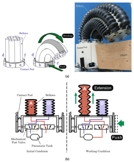
101] of the Tokyo Institute of Technology proposed a CRs consists of six bellows connected externally with a miniature air pump. The bellows bend based on mechanical reactive system and do not require any electronic equipment. The driving principle is shown in . The change in the length of the bellows under air pressure causes the robot to bend and grasp the objects. This electronicless actuation methods expands the range of applications for robots.
Figure 14. (
a) Soft pneumatic origami-inspired robot [
99]. (
b) Internal and external structure of the robot [
102].
Figure 15. (
a) Schematic diagram of Series Pneumatic Artificial Muscles (sPAMs) continuum robot; (
b) Two different states of pneumatic muscles, the left is the deflated state, the right is the inflated state [
100].
Figure 16. (
a) The pneumatic CR consists of six identical bellows; (
b) Diagram of value [
101].
The CRs using pneumatic actuation has the advantages of fast reaction speed, fast deformation, light weight, but at the same time there are also some shortcomings: (a) To obtain high seal, it is difficult to achieve the miniaturization of the drive equipment, the need for external gas pipe, air compressor and other complex structure; (b) The air cavity in the inflatable expansion will burst and so on if you do not add the limit layer. Therefore, the pneumatic actuator still needs to be optimized and innovated.
2.4. Smart Materials Driven
The common actuation way of CRs usually requires external motor to provide energy Which is connected to the body of CRs by circuit and will undoubtedly affect the flexibility of CRs. Smart material actuation has emerged in recent 30 years [
38]. The commonly intelligent materials including SMA, EAP, DEA, and so forth [
103,
104,
105]. Because the intelligent material can be used as a CRs ontology or embedded in the robot body without rigid motor, and the energy source can be natural energy such as light, temperature or humidity. Smart materials actuation can achieve the integration of CRs and driven system as well as the flexibility. DEA, EAP, IPMC and other actuation material need external electric field to complete driving due to their own properties, which limits the application scope of CRs based on smart material driven to some extent. So in recent years, scientists have been looking for new CRs actuation materials.
Shape Memory Alloy (SMA) is a kind of material composed of more than two kinds of metal elements. Its mass is small, and easy to realize the miniaturization automation and noise-free working of the actuator. The driving principle of SMA is to change the high temperature austenite into the low temperature martensite under the high temperature, and its original shape is damaged and deformed, which drives the robot to move. The driving energy of SMA need not completely rely on electric field, but also change the temperature of the robot body with the help of light energy [
106]. At the same time, the electrothermal effect of SMA has the defect as low drive frequency, which limits the movement of CRs. Kim et al. in Reference [
107] have proposed a method that relies on the optical effect of SMA, which is still based on optothermal and optical trapping effects of laser to cause temperature change, but higher sensitivity compared to the traditional thermo effects. The micro-robot is controlled by a laser that provides wireless space and time selection. During the actuation process, the robot exhibits crawling movements, including those triggered by the SMA, to remove the surface adhesion, photothermal, and propulsion caused by the optical trap effect. Optical driving does not require wires and pipes, as electric drives do, nor do magnetic driving require many external devices, making robotic systems more autonomous and lightweight. As an unfettered stimulus, light can be more flexible to drive the robot. In addition to driving based on thermal effect, optical driving can also be actuated directly through optical effect with the help of photosensitive materials. Alcaide et al. [
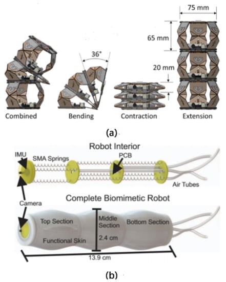
102] used SMA springs and silica gel to make a three-stage worm-like robot. The robot was composed of three identical parts, each with three SMA springs at 120 degrees and made of silicone skin, as shown in b. For the purpose of enhancing the operational capability of CRs in finite space, Tian et al. [
108] proposed a new central support structure with the spiral cutting mode. By analyzing the different cutting modes of thin-wall tube of superelastic NiTi SMA, the spiral hollow scheme was chose. The spiral hollow scheme was selected through analysing different cutting patterns of the thin-walled superelastic NiTi SMA tube. For the sake of providing a reference for the design and modelling methods, they systematically introduced from design method to manufacturing process of the central support structure using superelastic NiTi SMA material. Due to the advantages of SMA spring with high power density, compact structure and MRI-compatibility, Shao et al. [
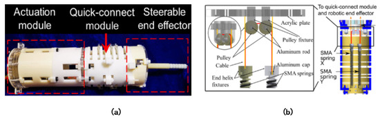
104] proposed SMA spring-based actuation module and integrated it with quick-connect module and steerable end-effcetor into a highly compact and adaptable MRI-condition system, thus simplifying the surgical procedure of MRI room. Each drive cable is connected to the SMA spring through the end helically-threaded fixture so that the cable ends with the aluminum cap fixed in the clamp and the SMA spring is tightened on the clamp (as shown in ). In conclusion, SMA actuation structure is light in weight and can be miniaturized, but the temperature is difficult to control and the drive frequency is low.
Figure 17. (
a) Prototype of the SMA-actuated neurosurgical robot composed of three modules; (
b) Detailed composition of the actuation module [
104].
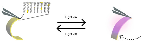
Jiaxin Shi of Peking University prepared GO (GO)/rGO (reduced GO) Janus films with a thickness of 15 um using laser direct writing technology. This film can respond to change in environmental humidity, and the reaction effect is best at a thickness of 15 um. A leaf grabber was prepared by using this actuator to grasp leaves in humid environment. This overcomes the problem that traditional intelligent material is difficult to arrange electric field in humid environment. Marina et al. developed a light driven robot with liquid crystal network (LCN) as the raw material. The robot uses an external LED as the power source. When driven by specific wavelength light, the robot legs made of liquid crystal network will be deformed as shown in to push the robot forward. In addition to the simplicity of the driving system, light driving has a higher driving efficiency than electric driving [
109].
Figure 18. The transformation of a robot under light [
109].
2.5. Magnetic Actuation
Magnetic driven is a remote controlled way to control and navigate the robot motion. Because magnetic fields can transmit energy wirelessly, the robot’s driven system is very light. At present, the magnetic drive of robot depends on the arrangement of magnetic field on one hand and the application of magnetic material on the other hand [
110,
111]. Joyee et al. [
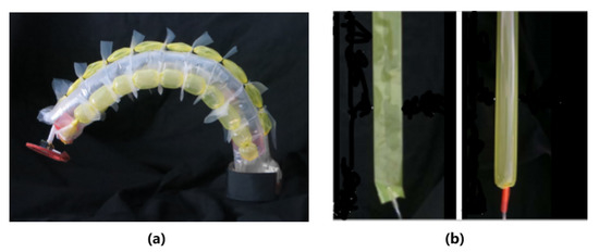
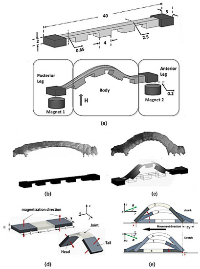
112] proposed a soft robot based on magnetic drive, which is inspired by inchworm in nature. This robot imitates the shape and movement mechanism of inchworm and is manufactured by 3D printing. The driving of the robot depends on the cooperation of magnetic field and hysteresis friction. Through the reasonable arrangement of magnets, the friction between the robot’s leg and the substrate can be controlled, and the crawling movement of the robot can be realized.
Xiang et al. in Reference [
113] also used three-dimensional Helmholtz coil to construct a uniform magnetic field in any direction of space and controlled various motion states of the micro-CRs based on magneto-elastic composite materials by using the uniform magnetic field. The structure of the crawling robot is shown in d. Its head and tail are made of two magnetic materials with the same size and opposite magnetization direction. The middle part is made of elastic material, which is referred to as joint later. If there is no magnetic field, the robot is in a natural flat state. When the external magnetic field intensity is not zero, the robot is subjected to magnetic torque, gravity, supporting force, friction and other external forces, and its body is bent into arch. And when the external force reaches a certain degree, the robot can make various actions.
Figure 19. (
a) The model of the 3D printed robot; (
b,
c) The state of a robot at rest and bent; (
d,
e) A full one-step crawl consists of a continuous contraction and stretch [
112,
113].
The magnetic actuation can produce high-speed motion output and force output, but the traditional magnetic drive is equipped with a magnetic field generator outside, which will make the robot structure less compact. At the same time, the biggest disadvantage of the magnetic drive is that the robot’s motion range will be limited to the magnetic field working area, which brings great restrictions to the robot’s motion. At present, the main research center of magnetic actuation is the combination of imaging technology and the search for biodegradable magnetic materials to improve the application of magnetic driven robots in medical surgery. In addition, finding a magnetic field generator with a wider coverage is also the direction of future efforts. As a driving method that can realize remote control, magnetic actuation has great potential in the medical field. At the same time, magnetic actuation is more accurate than other driving methods. When this kind of robot develops to a certain extent, it can be used to avoid the pain and damage to the human body caused by surgical wounds.
This entry is adapted from the peer-reviewed paper 10.3390/act9040142