By embedding conductive yarns in, or onto, knitted textile fabrics, simple but robust stretch sensor garments can be manufactured. In that way resistance based sensors can be fully integrated in textiles without compromising wearing comfort, stretchiness, washability, and ease of use in daily life. The many studies on such textile strain sensors that have been published in recent years show that these sensors work in principle, but closer inspection reveals that many of them still have severe practical limitations like a too narrow working range, lack of sensitivity, and undesired time-dependent and hysteresis effects. For those that intend to use this technology it is difficult to determine which manufacturing parameters, shape, stitch type, and materials to apply to realize a functional sensor for a given application.
Thanks for checking. The entry will be online only after your submission,which is free. We will help you layout and link your article at the entry. Hence more scholars and students can benefit from it. (Please remove this note when submitting.)
1. Introduction
Garments are intimate, close to the body and have a natural potential for collecting and monitoring body-related signals. Whereas in the early research of electronic textiles (or e-textiles), off-the-shelf sensors, electronic parts, and connecting wires were simply added to the textile, recent developments now allow for an almost complete integration of sensor and actuator functions in a textile [
1,
2]. Garments with well integrated electronics can be personalized, are comfortable, unobtrusive, and do not show visible connecting wires and sensor electrodes. Such functional clothing therefore has a much higher chance of being accepted to be worn in everyday life situations. In the near future stretch sensors will be embedded into everyday objects like pillows and car seats and we will use them during our fitness workouts, to monitor and correct our posture or during our virtual reality gaming. Apart from that, strain sensor garments are particularly beneficial for rehabilitation purposes where there is an urgent need for monitoring the recuperation of impaired body kinematics in situations of daily life activities [
3]. Although textile strain sensors are now being evaluated in clinical rehabilitation settings, they still seem to lack sufficient resolution [
4].
The era of smart textiles started with the introduction of conductive yarns and fabric at the end of last century which enabled it to integrate sensors and interconnections in garments in an unobtrusive way [
2,
5]. Conductive yarns are usually blending of traditional textile fibers and thin metal filaments like stainless steel, copper, or metal coated fibers consisting of a polymer core and a thin metal cladding (usually silver). Because of the blending with traditional textile fibers these conductive yarns still have their textile like properties and appearance. Current yarn manufacturing processes enable the production of yarns with non-conductive filaments wrapped around conductive core fibers. Such composite yarns have a fully textile appearance and are electrically insulated at the outside, and thus may prove useful as conductor lines in future e-textile applications [
6,
7]. An alternative way to achieve insulation is by coating the conductive filaments with micrometer thin polyurethane (enamel) layers. These types of insulated conductive yarns are however still not widely commercially available at present.
Reviews on wearable and flexible sensors in general are given by [
1,
2,
8,
9,
10,
11,
12,
13], whereas [
14,
15,
16] more particularly focus on textile strain sensors. Textile compatible strain sensors can be produced in three ways: (1) by integrating prefabricated stretchable sensor yarns in a garment; (2) by coating an existing fabric surface with a conductive substance, and (3) by integrating loop structures of conductive (non-stretchable) yarns in a textile fabric. In the latter case the resistance changes result from changes in contact resistance between loops of the conductive yarns during stretching. Sensor yarns or fibers can be manufactured by coating or dyeing yarns with a conductive layer or by embedding conductive particles in a stretchable polymer matrix [
14,
15,
16]. In both cases the yarn resistance changes when stretched and sensor garments can be constructed by integrating them into the textile. Examples are the coating of stretchable yarns with carbon nanotubes [
17], polypyrrole [
18] or PEDOT [
19], wrapping them with graphene film [
20,
21] or dyeing with silver nano crystal precursor solution [
22]. Composite yarns were fabricated by adding e.g., carbon black [
3], carbon nanotubes [
23] or by blending with PEDOT solution [
24]. Most of these sensor yarns show a high sensitivity, stretchability and good cyclic behavior. Although these yarns thus show high potential for future use as textile sensors, they are still in a relatively early research stage and require dedicated and well controlled processing, with the recently published kilometer scale conductive yarn sensor as the notable exception [
24]. Coated fabrics (as studied in e.g., [
25,
26,
27,
28]) on the other hand have a lower sensitivity and tend to wear during use [
14]. The advantage of the third category, the embedding of conductive loop structures in fabrics, is that the technology is directly accessible since it can be manufactured in mass production with standard equipment and uses commercially available types of yarns.
2. Knitted and Stitched Strain Sensors
In this section we will discuss the manufacturing details (types of yarn and knitting parameters) and electromechanical behaviour of knitted and stitched structures, which are able to detect and monitor deformation. The focus will be on sensors which can be knitted with a computer controlled knitting machine and commercially available conductive yarns. Knitted fabric sensors can easily be stretched to over 100%, and such behaviour is indeed often reported. However, the applications that we have in mind are for on the body worn garments where strains are not larger than 35–45% [
3]. For respiration monitoring the sensing range of interest is even smaller (up to 5%). While discussing the sensitivity and other properties we will therefore in the following limit ourselves to the first 40%. The ideal sensor properties for these type of applications can be formulated as [
42]:
- -
-
Wide working range (up to 45% for measuring stretch on the human body)
- -
-
High enough gauge factor (sensitivity)
- -
-
Low hysteresis
- -
-
No signal drift
- -
-
Good repeatability (i.e., after multiple cycles and after washing)
2.1. Knitted Sensors
2.1.1. Strain Sensitive Knitted Structures (1999–2009)
The number of published studies on knitted strain sensors in which details are given about the stretch strain behaviour and electrical responses are limited. One of the first studies showing the usefulness of textile based sensors is that of Farringdon [
43]. They knitted 10 mm wide sensor strips from conductive fibers with a nominal resistance 1 MΩ/m. These sensors were sewn on a jacket to monitor limb and upper body motion and had a quite high gage factor (close to 17 for the first 20% elongation). Unfortunately no details about the conductive yarn and knitting parameters were given. Later on Vogl et al. [
44] used the same idea to manufacture simple textile user interfaces by stitching conductive yarns on elastic fabric strip.
Another early study was that by Bickerton [
45] who used conductive carbon fibers to construct a knitted fabric sensor with an initial resistance of about 90 kΩ which increased up to 460 kΩ at 30% stretch (
GF = 14) and had a usable working range up to about 50%. He interpreted the shape of the resistance curve in terms of fiber slipping during extension and the associated increase in conducting path between contact points.
The Advanced Textiles group of Tilak Dias (Nottingham Trent University) did much of the preliminary work on knitted textile sensors and claimed a first patent in this area [
28]. Some details are given in [
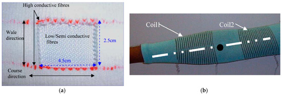
35] who describe relatively wide knitted sensor mesh structures of 45 mm (course) by 25 mm (wale) directions (a). Their measurements show that these sensors mesh are much more sensitive in course direction (
GF = 2.4 over the first 10% stretch) compared to wale direction (
GF = 0.42, over the first 10%). The sensitivity quickly levels of after 10% stretch. No details about the yarn types are given however. In his 2006 study, Wijesiriwardana [
46] also considered a different way of strain sensing by measuring the change in inductance between two knitted conductive coils after a linear or angular displacement. This technique could not only be used for respiration monitoring but also for angular movement monitoring on fingers and arms (b). They claimed that these types of sensors are less sensitive to temperature drifts as well as to aging due to washes as compared to resistive transducers. These types of sensors can in principle be used both as linear and as angular sensor.
Figure 1. (
a) Knitted sensor [
35]; (
b) Knitted coil sensors in arm sleeve [
46].
The possibility to continuously monitor the body kinematics of patients during daily life would be a breakthrough in the rehabilitation field [
47]. The Pisa group in a collaboration with Smartex have been working on this since the early 2000s. Their early work considered sensing fabrics constructed by impregnating fabrics with conductive polymer or elastomer coatings [
48,
49]. Because of relatively low sensor accuracy, long response time, and hysteresis effects, the group then developed a series of knitted sensors based on a carbon filled nylon fiber (Belltron, [
47,
50] and references therein). The sensor discussed in [
47] had a gauge factor of about 6.7, a working range of at least 10% and an acceptable hysteresis. In subsequent work they build and investigated several health care systems, as summarized in [
51,
52]. Sensors were fabricated by applying a conductive carbon filled silicone rubber coating to the fabric or by constructing knitted strain sensors. In [
51] they presented a knitted sensor with gauge factor 0.75, high linearity (up to 18% strain) and low hysteresis. Their findings suggest that hysteresis is suppressed by applying the conductive yarn in an ordered structure. Although they were not clear how this is done, the most likely interpretation is that they achieved this by using the plated knitting technique.
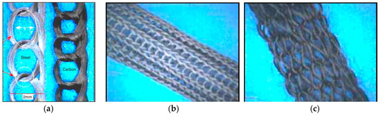
Zhang [
53] knitted heat resistant structures consisting of pure steel and carbon yarn bundles (). They argued that the change in contact resistance between conductive wire loops is the key factor for the electromechanical response of knitted strain sensors. For the experiments, they used conductive yarns consisting of 120 stainless steel fibers of 30 μm diameter, knitted into a plain knitted fabric with wale and course densities of 26 and 40 units per 50 mm. Their results indicated a gauge factor of about −10 over the first 10% stretch. After 20% stretch the resistance almost dropped to zero, most probably since they used only pure stainless steel fiber yarns without support yarns. The main focus of their 2005 work [
54] was to model the electromechanical behaviour of the knitted conductive networks shown in . Their experimental data showed that such networks have a linear response up to 10% and a gauge factor of about −10.
Figure 2. (
a) Knitted single warp steel and carbon structures; (
b,
c) tubular structures [
53].
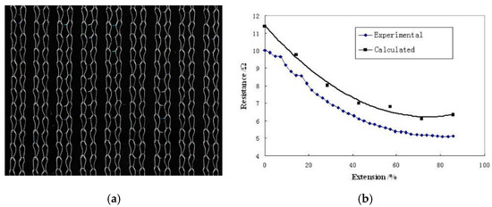
Yang [
55] modelled the electrical performance of knitted 1 × 1 rib structures. These structures showed a resistance decrease while being stretched, an effect which was well predicted by their model (see ). The gauge factor for the first 20% stretching turned out to be close to −1.1.
Figure 3. (
a) 1 × 1 rib knitted structure; and (
b) its elongation behaviour [
55].
Li and coworkers [
56] measured the confining pressure and electrical resistance of fabrics manufactured with eight different knitting stitches. Since their focus was on the confining pressure they did not mention the resistance changes with strain. Similarly, in a later work [
57] they used silver coated polyamide yarns (Statex) of 0.295 mm diameter and 100–200 Ω/m conductivity and determined the electromechanical behaviour of (i) single yarns, (ii) looped yarns, and (iii) an intarsia knitted yarn structure (together with a 58 tex cotton yarn). In that paper, however, they only reported resistance changes versus applied load (and not strain) so gauge factors could again not be calculated.
2.1.2. Strain Sensitive Knitted Structures (2010–2020)
Zieba [
58] constructed a knitted respiration sensor consisting of a cotton yarn base fabric a 20 mm band of knitted silver plated polyester yarns (Xsilver, China). No details about knitting and gauge factor were reported but the respiration measurements results appeared reasonable.
In a series of publications the group of Ozgur Atalay (University of Manchester) studied the behaviour of knitted strain gages in more detail. In their 2013 study they used a silver coated nylon yarn (235 dtex, 200 Ω/m) plus several elastomeric yarns and varied the input tension of the elastomeric yarn to produce fabrics with different compactness [
38]. The conductive yarn was embedded in the interlock base structure in a series of single jersey loops located only on the technical face of the fabric (). The run-in tension was varied between 0.062 and 0.125 cN/tex. For each of the three fabrics they determined the wale and course density, stitch length and Tightness Factor (Equation (3)). They observed a bilinear electromechanical response with a gauge factor 3.7 below 19% strain and 2.2 above, as well as hysteresis effects. The most tightly knitted structure had the highest linearity (
GF = 0.75). The fabrics could be extended up to 350% before breaking and were seen to be stable during cyclic testing. With the increase of fabric tightness the relaxation effects increased slightly (from 4 to 16%) [
38].
Figure 4. (
a) Loop-wise embedded conductive yarn in knitted interlock structure; (
b) electromechanical response [
38].
In a follow-up study [
59] they used a silver coated nylon yarn (Swicofil, 2 ohm/cm) and three types of Lycra base yarn covered with wrapped nylon filament (800, 570 and 156 dtex, 8 cN feeding tension). The 800 dtex Lycra yarn was studied in more detail and the conductive yarn feeding tension was varied from 5, 10, to 20 cN. It showed that at lower yarn feeding tension the loop structures were looser and the conductive contact area was increased. The 20 cN fabric showed lowest hysteresis and a bi-linear electromechanical response (
GF = 1.86 up to 18% and 0.68 up to 40%, b). Increasing the number of conductive courses (separated by non-conductive material) did not increase the performance due to increased tendency of the fabric to buckle. As before, the sensors were stable and showed a low drift. In their 2015 paper [
60] they optimized the knitting of multiple line conductive samples and produced a sensor for respiration monitoring which was linear of to 8% with
GF = 3.44 and which did not show hysteresis (800 dtex Lycra base yarn with 235 dtex silver plated nylon,
TF = 1.39).
In their last study [
61] they compared two types of conductive yarns (Bekinox polyester blended stainless steel and silver plated nylon), plain versus interlock base structure and elastic versus non-elastic base structure yarn. During knitting, conductive and elastic yarn are fed to same needle (plating technique) to be able to shield the back of the sensor from skin contact. From their electro-mechanical tests, it turned out that sensors with a non-elastic plain knitted base structure showed a negative gauge factor whereas elastic structures resulted in a positive gauge factor. They attribute this difference to the elastic tension which initially compressed the conductive loops in the elastic structure but which is absent in the non-elastic case. All of their results on these types of sensors, however, showed a large scatter and reproducibility, which is probably due to the lack of sufficient contraction in the sensor area compared to the base structure which may lead to buckling of the sensor part. They explained the unreliable response of their stainless steel sensors to the irregular orientation of the steel fibers within the structure. Reported gauge factors in their paper ranged from −0.7 to 1.05.
A systematic study on knitted sensor performance was conducted by the textile group of the Niederrhein university [
62]. This group studied the effect of knitting structure on the strain sensing capability and considered the following parameters:
- -
-
Stitch type: double face, single face, Milano rib and full cardigan;
- -
-
Stitch cam settings NP = 9.5 (small), 10.5 (medium) and 11.5 (large);
- -
-
Conductive yarn type: four types of S-Shield PES and cotton blended stainless steel yarns (single thread, two thread; 50/2 with 20% steel fibers or 15/1 Nm with 50% steel);
- -
-
Fabric orientation: 0, 30, 45, 60, and 90°.
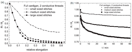
They calculated wale and course densities as well as the loop lengths, which would allow them to relate the observed electromechanically behaviour to textile parameters like the tightness factor. Regarding the stitch types they observed that the single face fabrics often showed oscillatory time dependence and that the Milano rib structure had a rather small sensitivity. The full cardigan and the double face structures gave the best results ().
Figure 5. Effect of stitch size on electromechanical behaviour of full cardigan fabrics. (
a) With respect to strain and (
b) with respect to time [
62].
also shows that for these knitted structures the resistance decreases when stretched (negative gauge factors) and that after the first 10% stretch the sensors rapidly became less sensitive. Furthermore, the figure shows that the smaller stitched structures had a considerable lower gage factor than the medium and larger ones (−2.2 versus −5.8, as obtained over the first 10%). On the other hand, the signal decrease over time of the smaller stitched structures was considerable better than the more dense structures (b).
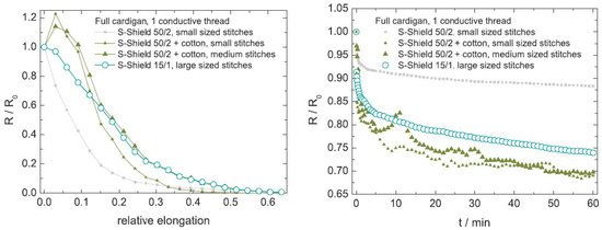
The study of Ehrmann et al. [
62], showed that the difference between the 50/2 conductive yarn containing 20% steel filaments and that of the 15/1 yarn with 50% steel was not large, as depicted in . The 50/2 yarn had a smaller working range (up to 15 to 20%) but also a considerable smaller relaxation. More interesting to note is that the blending in of cotton threads resulted in undesirable (first increase, then decrease in resistance) as well ambiguous results (peaks and scatter in relaxation experiments). This confirmed the conclusions of Atalay et al. [
61] that mixed filament conducting yarns were unsuited for constructing knitted strain sensors. The authors also showed that when elongated in wale direction (90°) the sensitivity increased at the costs of a decreased working range (limited to 20%) and relaxation behaviour. Interestingly enough, all tests at 30, 45, and 60° closely followed this wale direction behaviour.
Figure 6. Effect of yarn materials [
62].
Wang et al. [
63] proposed an electrical resistive mathematical model using an empirical relation for the inter-loop resistance increase during stretching and validated their model with measurements at 2, 5, and 10% elongation. Their results showed linearity of the knitted sensors up to 5% and gauge factors of 5 to 10. Unfortunately, most experimental conditions were not reported and a good comparison between experiments and model was missing.
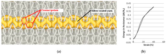
Oks [
64] knitted plain stich sensors with alternating conductive and non-conductive courses (). Due to the compressive effect of the elastomeric yarns the conductive courses made resistive contact when unloaded but separated gradually when loaded (in wale direction). For the experiments they used
Figure 7. (
a,
b) Alternating courses of conductive and non-conductive yarns; (
c) resistance change [
64].
-
Base yarn: Elastane/polyester 22/78 yarn
-
Function non-conductive yarn: 25 Tex cotton
-
Functional conductive: Shieldex dTex110 and dTex110*2
These sensors work well for strains up to 5 or 10% and can be designed such that the resistance increases to infinity if the strain exceeds a certain value (if the conductive courses are separated too much, see ). This type of design however seems less suitable for work ranges above 20%. The sensors showed hysteresis when the knitting was done at high course density (16.8/cm). When knitted with lower course density (15.2/cm) the hysteresis was almost absent. The resistance change with applied strain curve was non-linear (c), but when evaluated over the first 5% strain the gauge factors varied between 20 and 42. If the 110*2 double yarn was used the linearity was better but the gauge factors were a bit lower (10 to 30). The sensors were seen to be stable during 10 cycles of loading. They presented knitted sensing gloves and socks but did not discuss their properties.
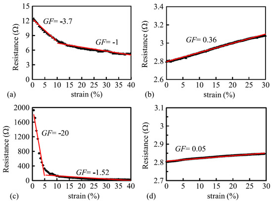
Xie [
65] fabricated a yarn consisting of 50% cotton and 50% 8 μm thin stainless steel fibers which looked and felt like cotton and which were robust and washable. Jersey knitted sensors showed a high, negative gage factor of −20 when loaded in wale direction but after 5% strain this diminished to −1.52 (c). Due to this large change this type of sensor is in its current state of less practical use but may show to have a large potential when improved. In course direction the gauge factor changed from −3.7 to −1. As a comparison they also tested a sensor knitted from silver plated multifilament nylon (110 dtex/40f). These sensors were linear up to 30% strain and had gauge factors of 0.36 (course direction) and 0.05 (wale direction, d). This once again shows that silver plated nylon yarns are much more suitable for sensor construction than stainless steel filaments blended with non-conductive material.
Figure 7. Course-wise response of (
a) Cotton-steel knitted sensor and (
b) nylon plated material; Wale-wise (transverse) responses of (
c) cotton-steel and (
d) nylon plated material [
65].
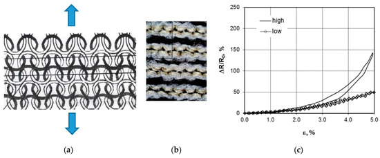
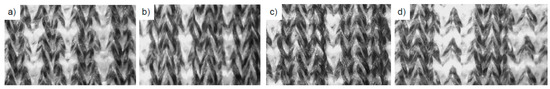
Rib structures have the tendency to contract laterally, resulting in a pattern in which knit stitches come forward and purl stitches recede. They provide highly elasticity and are therefore often used for cuffs and edges that require form-fitting. During stretching the vertical rib structures unfold which makes them an interesting candidate for (large deformation) stretch sensors. A detailed study on the effect of the rib structure on the electrical behaviour was performed by Raji [
66] for a future application as respiration sensor in a Smart Bra. They used a silver coated nylon yarn (77 ohm/cm resistivity) as a conductor and both bare strand (BS) and nylon covered yarn (CY) spandex as the elastic yarns. The four types of mock rib structures studied are shown in . They reported the main textile parameters (wale and course density and fabric dimensions) as well as the resistance changes during cyclic loading. Their main findings were: Gauge factors of samples with the bare strand elastane (BS) had systematically higher values (
GF = 2.4, 2.8, 2.3 and 2.2 for the 1 × 1, 1 × 3, 1 × 2, and 2 × 2 ribs) than those of the covered yarn elastane samples (
GF = 1.25, 1.5, 1.6, and 1.4). The sensor performance of the CY 1 × 1 and 1 × 2 as well as the BS 1 × 3 samples were seen to decrease somewhat after 50 days of testing. Unfortunately, no direct resistance versus strain plots were reported so no conclusion about linearity can be given.
Figure 9. Images of knitted rib structures. (
a) 1 × 1, (
b) 1 × 3, (
c) 1 × 2 and (
d) 2 × 2 structure [
66].
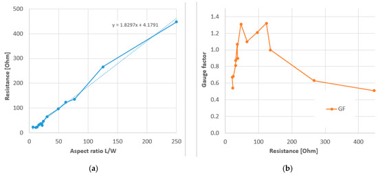
In a subsequent paper they selected the CY 1 × 1 structures and varied the knitted sensor geometry for aesthetic reasons [
67]. They concluded that complex shaped samples delivered poor repeatability and noisy results, probably because of the truncating of conductive yarns inside the non-conductive gauge areas. An extended test series with 14 rectangular samples with different aspect ratio showed first of all that the gauge resistance increased linearly with the aspect ratio, as expected from the resistance expression Equation (7). Not shown by the authors but based on their data, the surface resistivity could be determined as 1.83 Ω/sq (see ). Combining this with Equation (7) and the given linear resistivity of 77 Ω/cm this implies a fabric thickness of 0.24 mm, which could be realistic. Secondly, their results showed that the gauge factor of the rib knitted sensors have a maximum between 40 to 120 Ω. They reasoned that the decrease in gauge factor below 40 Ω was due to an increased resistive heating resulting in a less efficient sensing and that for too high resistances the current becomes too low to give reliable results. Although the latter interpretation is doubtful (other studies worked with sensors of several kΩ [
50]), the idea that gauge factors show a maximum depending on their geometry is interesting to further explore for other knitting structures.
Figure 10. (
a) Resistance and (
b) gauge factor rectangular knitted sensors of different length and 6width; Based on [
67].
Ou et al. [
31] used a 1000 Ω/m 450 denier (500 dtex) silver plated nylon blended with non-conductive yarns and an interlock knit structure. They first knitted a series of rectangular sensors with aspect ratios varying between 0.31 and 320 and confirmed the linear scaling with
L/
W, as expected from Equation (7) and also found in . The surface resistivity was 2.63 Ω/sq, which is of the same order as the value for the study discussed above [
67]. The sensitivity to stretching was only shown for a single sensor geometry (with 60 Ω initial resistance). The sensor response was more or less linear but the strain range and sensitivity could not be determined since the sample length was not reported.
4.1.3. Modelling of Knitted Sensor Electromechanical Behaviour
About the physical interpretation for the observed decreasing and increasing resistance-strain curves there seems to be a general consensus in the literature, although they have never been listed together. Summarizing the literature, we can discern the following four distinct stage during the stretching of a knitted conductor:
-
Stage 1: Reduction of contact points: the opening of the structure (gradually) disconnects contacting loops which were connected in the initial state due to elastic contraction of the base structure. This is typical for the first 10–20% stretching and causes a resistance increase;
-
Stage 2: Yarn slippage and shifting of contact points due to a rearrangement of the knitted structure. This results in a larger yarn length (and resistance) between a fixed number of contact points and can be a dominating effect for high resistance yarns. Between 10 and 40% strain;
-
Stage 3: Increased contact pressure between hooked conductor loops. This effect starts to play a role for strains above, say, 20% and causes the resistance to decrease. In bare metal conductive yarns this may start earlier and is the dominating effect;
-
Stage 4: The stretching of the conductor yarn segments itself. This occurs when all slack is out of the system and loop segments have straightened. Depending on the structure this may start above 50 to 80%. For metal coated and carbon filled yarns this results in an increase in resistance whereas for yarns consisting of metal filaments blended with non-conductors the resistance decreases due to the squeezing effect.
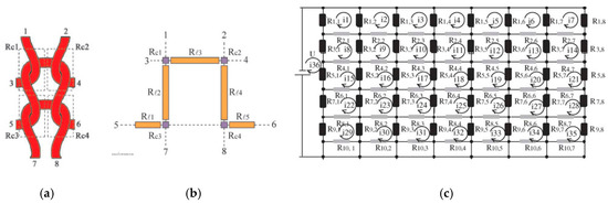
The modelling is done by first calculating the resistance and then separately addressing the above four stages. We will not discuss the literature on resistance modelling in detail but in general this is based on first considering the resistances of loop segments and contacts in a unit cell (a), followed by calculating the equivalent resistance of a network of such unit cells (b). This always led to unnecessary large and complex expressions which are difficult to handle and did not give much insight. Refreshing is therefore to follow the way of reasoning of Li et al. [
68]. These authors take into account that most segment resistances are of equal value and that adjacent unit cells therefore act as balanced Wheatstone bridges through which no current flows.
Figure 11. (
a,
b) Unit cell of knit [
68]; (
c) Resistor network approach [
53].
The current then in fact appears to flow only along the courses without any interaction between adjacent courses, which considerably simplifies the network model (see ). Note that the upper and lower courses of the conductive area have a resistance which differs from those in between due to the fact that the outer part of the loops there are not in in contact with other conductors and miss the two contact resistance points (points Rc1 and Rc2 b).
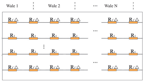
Figure 12. Simplified equivalent network model [
68].
For structures with more than three courses the equivalent resistance then becomes [
68]
in which both
R1 and
K depend on the contact resistance. It is clear that for large enough number of courses the resistance scales with the ratio of the number of wales
nw and courses
nc, or as the length over width ratio
L/
W, as seen in Equation (7).
Next the question is how to calculate the resistance increase due to stretching. Although some studies on the topic are reported, a generally accepted theory is not available yet. Stage 1 (the gradual decrease of contact points) is discussed by e.g., [
60] who take into account Holm’s contact pressure theory. Xie et al. [
69] address stage 2 and assume that during stretching the yarns slide, resulting in longer loop segments in tensile direction (
Rl3 in b). The loop segment length changes during stretching were empirically determined and with this and their (complicated) network model they could correctly predict the overall resistance change due to stretching. In other works often the empirically determined contact resistance variation with pressure is used to describe stage 3 [
53]. The fourth stage can be taken into account by first estimating how the yarn stretching relates to the macroscopic strain in the structure and then using the (measured) resistance increase of the conductive yarns.
2.2. Stitched Sensors
With knitting the sensor placement and orientation is limited in flexibility because of the fact that many hidden conductive tuck yarns are needed to realize more complex shapes as well as orientations different from wale and course directions. Although these hidden yarns are not visible, they tend to corrupt proper functioning of the sensor [
67]. Stitching, on the other hand, can be directly applied to a finished garment and is not limited on orientation direction. Moreover, stitched sensors have no perceptible compromise for user comfort and a minimal impact on garment production [
70]. The sensor response however relies heavily on the physical characteristics of the textile substrate to which it is stitched.
Much of the work on stitched strain sensors has been done by the group of Dunne (University of Minnesota). In their first work on the topic Gioberto and Dunne [
70] present a top-thread cover stitch stretch sensor using a silver plated nylon yarn (Lamé Lifesaver, 0.81 ohm/cm) on a 98% polyester/2% Lycra jersey knit fabric. The sensor had a work range of about 12% and a gauge factor of about 0.54. In their 2013 paper [
71], they tested overlock-stitched strain sensor using a Shieldex 235/34 silver coated nylon yarn (50 Ω/m) and five types of jersey knit fabrics with different elastomeric content. Their sensors turned out to have a work range between 18 and 29% and relatively small drift and hysteresis. Gauge factors were not reported but can be estimated to vary between 0.48 and 2.2. The sensor with the highest work range was the one stitched on fabric consisting of 82% nylon and 18% spandex. In another paper [
72] they compared overlock and bottom thread cover stitches using two, four, and five-ply silver plated nylon yarns (Shieldex 177/17, Shieldex 235/34 and a custom made thread). Their results showed that sensors fabricated with the two-ply thread were less repeatable and showed significantly more noise that the other sensors. The working range of the top-thread cover stich and overlock sensors are limited to 5–10% and 20–25%, respectively. The bottom thread cover stitch sensor, on the other hand, showed decreasing resistance upon stretching and had a working range to above 40% strain. They tested their sensors on a leotard and two types of shirts for a spinal posture sensing application. The sensors were stitched to the dorsal side along the spine and insulated with 3M7012 stitchless bonding film. Those tests showed that the T-shirts were less suitable for posture sensing since during multiple bending they tended to ride up on de body and do not slide back.
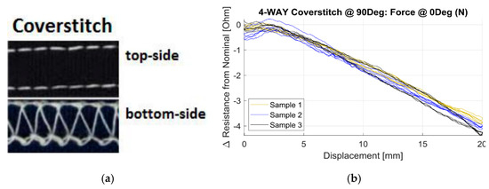
The response of stitched sensors depends on the stitch structure and the anisotropy of the base or substrate material whereas for the suppression of hysteresis it is important how the (elastic) response of the substrate or surrounding yarns are. In [
37] the effect of the substrate materials on strain gauges embroidered at different stitch angles was investigated. The authors used a two-way and four-way stretch weft knit as well as a double knit structure and Shieldex 235/34 four-ply silver plated nylon as the conductive yarn. The stitches considered were the ISO401 chain stitch and the ISO406 bottom cover stitch. They showed that the chain stitch had a considerable effect on local fabric stiffness (stiffness increase of 12% at 0° orientation and 200% at 60°). The sensors were linear up to at least 30%. The highest gauge factor was obtained for the two-way knitted fabric with chain stitch (
GF = −2.24) and the lowest was for the two-way knit fabric with coverstitch (−1.01). Remarkably the gauge factors did not depend much on the sensor orientation for all combinations tested. If on the other hand the force direction was varied the effects were larger. The transverse sensitivities of the two-way knit fabric with coverstitch sensor were unacceptable high (65% up to 98%), the two-way chain stitch and the four-way chain stitch combinations showed much lower values (4 to 12%). The chain stitch is thus the preferred stitch geometry. A typical example is shown in .
Figure 13. (
a) Coverstitch structure and (
b) resistance versus displacement curve [
37].
Ruppert-Stroescu and coworkers [
73] investigated the sensor properties of three conductive yarn types Shieldex 117/7 (a silver coated two-ply nylon, 985 Ω/m), Shieldex 234/34 (a four-ply silver coated yarn, 80 Ω/m) and Lame Lifesaver yarn (a three-ply silver coated yarn with 65 Ω/m resistance) on plain woven cotton fabric (muslin). Furthermore, they considered five stitch types (310, 304, 315, and 401, and adapted 304) with fixed stitch densities. It turned out that for some of the stitch/wire combination the resistance after stitching was considerably less than that of the bare wire (all per unit width) whereas for most other combinations this was not the case. Elongation tests were only performed with the bare threads so no gauge factors of the stitch types could be determined.
Vogl [
44] stitched conductive silver plated yarns on a small stretchable band and thus created stretch band sensors which can be used as future user interfaces. To construct this, they used silver plated nylon (Inventables, triple twine, 30 Ω/cm), a highly stretchable 70% polyester/30% elastodiene fabric and a zig-zag stitch with 3.3 mm width. The response during stretching however appeared to be quite non-linear.
Another stitched sensor study was performed by Greenspan [
74] with the aim to apply it for unobtrusive human movement monitoring. They selected a silver plated 22/1 dtex nylon yarn, since preliminary experiments showed that it had the highest strain sensitivity. They further considered three fabric substrates (nylon/10% spandex, polyester/10% spandex and cotton/5% spandex). The stitch geometries studied were 304, 402, 406, and 514. The 514 stitch (overedge stitch) showed negligible response to stretching (
GF close to 0) and was not further analysed. Note that such stiches however can be useful as interconnects in which resistance changes are often undesired. The best sensors candidates were the Zig-zag (304) and the chainstitch (402) on a cotton/spandex substrate. The Zig-zag on polyester/spandex combination however showed better repeatability after cyclic testing. The gauge factor as derived from their graphs was near 1.0.
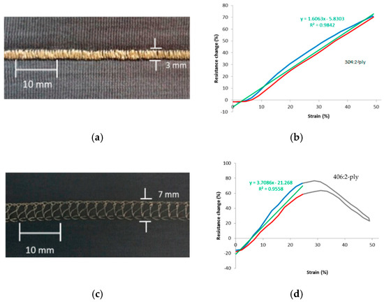
As mentioned above, the response depends on the substrate fabric, the yarn, as well as on the stitch structure. If the substrate shows hysteresis after stretching, the fabricated sensor will also. Tangsirinaruenart [
42] therefore suggested to first select the substrate fabric and then consider the yarn and stitch geometry. They evaluated six fabrics, two conductive threads (four-ply Shieldex 234/34 and two-ply 117/17) and four stitch types (numbers 304, 406, 506, and 605). Preliminary experiments showed that the fabric with the highest elastic recovery (93%) was a single jersey nylon (two-ply, 4.44 tex) with 25% spandex (7.78 tex) combination. Using that fabric they showed that the 304 stitch (the Zig-zag lock stitch) in combination with the two-ply wire gave the best results: gauge factor 1.61, working range 50%, good linearity, low hysteresis, and good repeatability (a,b). A more typical response cure is shown in d showing a resistance maximum and limited working range. Note that their experience with the two-ply conductive yarn is different from that reported by Gioberto and Dunne [
72] who concluded that these yarns resulted in noisy and less repeatable sensors.
Figure 14. (
a) Zigzag stitch and (
b) corresponding resistance plot; (
c) Coverstitch and (
d) corresponding resistance plot [
42].
This entry is adapted from the peer-reviewed paper 10.3390/s20247236