Magnetorheological elastomers (MREs) are magneto-sensitive smart materials, widely used in various applications, i.e., construction, automotive, electrics, electronics, medical, minimally invasive surgery, and robotics. Such a wide field of applications is due to their superior properties, including morphological, dynamic mechanical, magnetorheological, thermal, friction and wear, and complex torsional properties.
- magneto-sensitive smart materials,MREs
1. Introduction
2. Fabrication of Isotropic Magnetorheological Elastomers
3. Fabrication of Isotropic Magnetorheological Elastomer
In the case of SR, the fabrication of isotropic MREs is quite easy and simple. The first step in SR-based MRE fabrication is the thorough mixing of liquid SR with suitable additives, such as catalyst [73], silicone oil (SO) [31], PDMS [45], graphene nanopowder [97], or 1,3-divinyl-1,1,3-tetramethyl disiloxane [22], and suitable magnetic filler particles for sufficient time to obtain a uniform dispersion of particles in the solution [45]. The magnetic filler particles are usually added in the volume fractions, ranging from 5–40 vol%, whereas additives are added as per the required properties. Afterwards, this blend is placed inside a vacuum chamber for sufficient time to remove the trapped air bubbles during mixing [73]. After proper degassing, the blend is poured into plastic or metal molds. Then, the molds are again placed in the vacuum chamber for sufficient time for further degassing. As mentioned earlier, SR has the property of room temperature vulcanization, therefore, the solution is cured (vulcanized) in the molds at room temperature [23] or slightly higher temperature (65 °C) [95] after sufficient time, ranging from 10–2880 min [35,45]. In the case of any other polymeric matrix, high-temperature vulcanization is carried out.
On the other hand, the PUR-based MREs are fabricated by mixing PUR rubber with additives (SO) and magnetic filler particles (CIPs) thoroughly at room temperature [12] or a slightly higher temperature (67 °C) [61]. This mixture is then poured into molds and cured at a specific temperature and pressure (20 KNm−2) to get a final product [12,61]. Similarly, NR-based MREs are fabricated by mixing NR with filler particles homogeneously by two-roll mill or any other means and pouring into molds. Curing of NR-based MREs is performed in an oven, maintained at 180 °C under specific pressure (200 bar) for a specific time (10 min) to get the final isotropic MRE [27]. Furthermore, the fabrication of isotropic MRE from scrap tire rubber involves the separation of rubber from metals and fabrics, shredding into powder of 60-mesh size, and analyzing its chemical composition (usually 7% acetone extract, 5.45 ash, 32.9% carbon black, 54.6% hydrocarbon rubber). The Fe3O4 (60-mesh size) or Penta CIPs (6 μm) particles in 10–40 wt% are usually used as magnetic filler particles and sulfur, zinc oxide, stearic acid, and latex solutions as additives. The fabrication process of MREs from scrap tire rubber is comprised of several stages, including mixing of 100 phr of crumb rubber with 2 phr of sulfur, 1.5 phr of stearic acid, and 5 phr of zinc oxide for 15–30 min; addition of 15% latex solution; and further mixing for 15 min. Finally, the mixture is poured into molds and placed in a high-pressure high-temperature (HPHT) sintering device [92]. Sintering of molds was performed by applying a pressure of 25 MPa, heating to a temperature of 200 °C at a heating rate of 10 °Cmin−1 within 17–20 min, and soaking at this temperature for 1 h. The hot molds are then cooled to room temperature. The volume fraction of produced MREs can be derived using Equation (1) [33].

where dMRE is the density of MREs, dW is the density of pure reclaimed rubber, and dMP is the density of magnetite powder. The base densities for the pure reclaimed rubber and magnetite powder were 1.107 gcm−3 and 5.27 gcm−3, respectively [33,92].
4. Morphological Properties
Various characterization techniques—i.e., scanning electron microscopy (SEM), energy dispersive spectroscopy (EDS), X-ray photoelectron spectroscopy (XPS), Fourier transform infrared spectroscopy, and X-ray diffraction spectroscopy (XRD)—have been employed to explore the morphological properties of isotropic MREs. It has been reported that the morphology of SR- and CIP-based MREs comprises homogeneously distributed CIPs throughout the SR matrix [34]. The large size CIPs of 6.25-µm diameter exhibit fairly uniform distribution, whereas small diameter CIPs produce agglomerates in the matrix. In the case of small diameter CIPs, the distance between particles was observed to be smaller and filler–filler particle interactions was greater, resulting in agglomeration of particles [99]. The addition of 10 wt% silicone oil causes more homogeneous dispersion of CIPs in the SR matrix without any structuring or surface defect [29]. SEM images, a histogram of particle size, XRD, FTIR spectra of SR, and CIP-based MREs, having PDMS as an additive, are illustrated in Figure 4. It was found that the morphology of CIPs-free MRE validated the formation of nonporous composite elastomers due to vulcanization under vacuum conditions (Figure 4a). On the other hand, Figure 4b demonstrated the random distribution of CIPs in the SR matrix. Similarly, Figure 4c,d confirmed the random distribution of CIPs with 2.5-mm average particle diameter in the SR matrix in the range of 0.5–4 mm. Two broad peaks at 12° and 23° in the XRD spectra validated the presence of PDMS and amorphous nature of SR-based polymer composite, whereas intense peaks at 44.8°, 65°, and 82.3° confirmed the presence and crystalline nature of CIPs (Figure 4e). The FTIR spectra of this MRE confirmed the asymmetric stretching vibration motion of Si–O–Si bond by absorption band at 800 cm−1 and the bending motion of Si–OH group by a peak near to 875 cm−1 (Figure 4f). The stretching vibrations of Si–O, and Si(CH3)2 groups were also validated by peaks in the range of 1000−1100 cm−1. The additional absorption bands in the region of 1250 cm−1 and 2960 cm−1 presented the stretching vibration of Si(CH3)2 [23]. XPS spectra verified the results of FTIR spectroscopy, as illustrated in Figure 5.
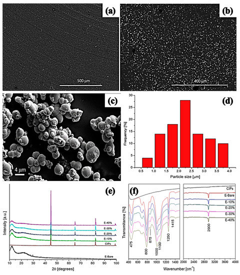
Figure 4. SEM micrographs of (a) CIPs-free MRE, (b) MRE with 20 wt% CIPs, (c) high-magnification micrograph of MRE, (d) histogram exhibiting CIPs size distribution in MREs, (e) XRD spectra, and (f) FTIR spectra of MREs [23] (reprinted with permission from ElsevierTM).
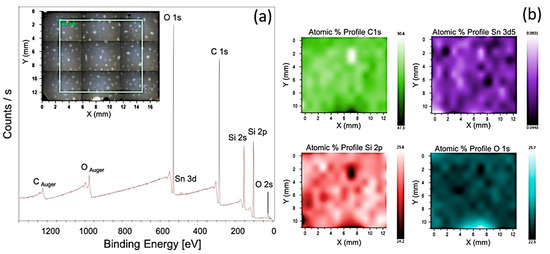
Figure 5. (a) XPS spectra of MRE with 20 wt% CIPs, demonstrating carbon, oxygen, silicon, and tin elements in the selected area, presented in inset figure. (b) XPS maps and atomic percentages of elements for the selected area [23] (reprinted with permission from ElsevierTM).
It has also been reported that the CIPs of 4–5 μm diameter exhibit uniform distribution in EPDM- and CIP-based MRE, whereas CIPs of diameter 8−10 μm demonstrate aggregation of 2–3 particles. This aggregation begins with the addition of 10 phr of CIPs and 60 phr of carbon black in the EPDM. The MRE with 5 phr of CIPs demonstrated the fair distribution of single CIP within the EPDM matrix without aggregation. In two separate MREs, containing 30 phr of CIPs and 30 phr of BIPs of a diameter of 4–5 μm, a combination of single-particle distribution and aggregation of 2–3 particles was observed. But the MRE containing 30 phr of CIPs demonstrated a very homogeneous distribution compared to BIP-based MRE [24]. Cvek et al. [30] reported the uniform dispersion of CIPs in both virgin and reprocessed thermoplastic elastomer (TPE)-based matrix CIPs without agglomeration and air bubbles. On the other hand, the morphology of PUR-based MREs, containing pure CIPs and PANI-modified CIPs, have also been explored. Compared to pure CIP-based MREs, homogeneous and agglomerated free morphology was achieved in the PANI-modified CIP-based MREs. A particular self-assembled structure of modified CIPs and excellent compatibility between the CIPs and PUR was observed in the PANI-modified CIP-based MRE, attributed to the bridging of the CIPs/PUR covalent bonds [91].
5. Fatigue Life of MREs
The equi-biaxial fatigue life of SR- and CIP-based MREs were determined by the bubble inflation method. Figure 20 shows the plots of total energy density vs. cycles under various concentrations of CIPs. Variations in total energy density were observed to be highly sensitive to CIPs concentration and stress amplitude. For MREs with CIPs content ranging from 15% to 30%, a decrease in total energy density was observed with an increase in cycles at higher stress amplitudes, whereas an improvement in total energy density was achieved with an increase in cycles at lower stress amplitudes. Irrespective of the applied stress amplitude, total energy density improved with an increase in cycles in the case of MRE with 35% CIP content. A decrease in total energy density at failure was observed when drawn against log10 cycles. This fact suggested that the total energy could be used to predict the fatigue life of MREs subjected to equi-biaxial loading [35]. Uniaxial and biaxial cyclic fatigue properties of NR- and IP-based MREs were investigated between constant strain limits. The uniaxial cyclic fatigue test demonstrated that MREs exhibited stabilized properties at the latter stages of cyclic tests and any change in their properties was attributed to the applied magnetic flux density. An increase in the modulus from 1.325 MPa to 1.413 MPa was observed at the 360th cycle and at strain amplitudes ranging from 0.04–0.08. This was an approximate increase of 6.5% in the 50-cycle block average modulus attributed to the magnetic field applied at the 360th cycle. On the other hand, the block average modulus increased from 3.562 MPa to 3.591 MPa at the 350th cycle and at strain amplitudes ranging from 0.04–0.57. This was an approximate 0.8% increase in mean modulus of the 50-cycle block associated with the applied magnetic field at the 350th cycle. After comparison, it was concluded that increased strain amplitude decreases the MR effect attributed to the increase in separation distance between the particles and reduction in screening effects, whereas the biaxial bubble inflation cyclic fatigue test performed at a low strain of 0.0–0.1 and magnetic flux density of 198 mT showed that an increment in modulus from 3.066 MPa to 3.132 MPa was observed at the 90th cycle. This increment is attributed to the 2.2% improvement in block mean modulus under a specific magnetic flux density. Under the application of relatively higher strain (0–0.5) and the same magnetic flux density, an increment of 1% was observed at the 90th cycle in the block average modulus from 3.375 MPa to 3.410 MPa. In the case of strain amplitude ranging from 0.4–0.5 and the same magnetic flux density, an increment of 0.4% was observed in the MR effect at the 90th cycle from 3.553 MPa to 3.570 MPa [84].
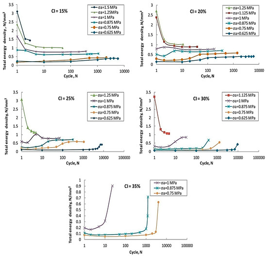
Figure 20. Plots of total energy density vs. cycles under different concentrations of CIPs [35] (reprinted with permission from ElsevierTM).
This entry is adapted from the peer-reviewed paper 10.3390/polym12123023