The use of electrically conductive materials to impart electrical properties to substrates for cell attachment, proliferation and differentiation, represents an important strategy in the field of tissue engineering. Carbon nanomaterials have great potential for fabricating electro-active structures due to their exceptional electrical and surface properties, opening new routes for more efficient tissue engineering approaches. The concept of electro-active structures and their roles in tissue engineering is discussed in this review, the most relevant carbon-based nanomaterials used to produce electro-active structures are presented. Particular emphasis is put on the electrically conductive property, material synthesis and their applications on tissue engineering. Different technologies, allowing the fabrication of two-dimensional and three-dimensional structures in a controlled way, are also presented. Finally, challenges for future research are highlighted.
- Electro-active scaffolds
- graphene
- tissue engineering
Note:All the information in this draft can be edited by authors. And the entry will be online only after authors edit and submit it.
1. Introduction
Tissue engineering is a relatively novel discipline, aiming at improving or replacing biological tissues. The use of scaffolds, physical substrates for cell attachment, proliferation and differentiation, is the most common strategy for tissue engineering [1,2,3,4]. These scaffolds must be designed according to specific requirements to create the appropriate environment for cell attachment, proliferation and differentiation. They must be biocompatible and biodegradable (the degradation rate must match the regeneration rate of the new tissue [1,2,3,4]), with proper geometry, morphology, porosity and pore interconnectivity [1,2,3,4]. Scaffolds must have adequate mechanical properties depending on the type of tissue, appropriate surface characteristics and must be easily sterilized [1,2,3,4]. A scaffold’s capacity to stimulate cells is also another important requirement.
Electrical signals are critical physiological stimuli that strongly affect cell behavior due to the cell proliferation impact on the cell membrane potential [5,6]. Electrical stimulations can redirect the alignment of random cells [7,8]. Some types of cells are aligned perpendicular to the vector’s direction of the electric field to minimize the field gradient go through the cell. Other cells are aligned parallel to the field vectors due to the electrical stimulation that causes rearrangement of the cell cytoskeleton. Additionally, the spreading direction of cells is also affected by the electric field [9]. Some types of cells migrate toward the cathode, while others toward the anode. Electrical stimulations may also affect the recognition of electrical signals and signal transduction within individual cells, gap junction intercellular communication, role of extracellular matrix and regulation of gene expression [10]. Based on these effects, applied electrical stimulations affect not only cells’ directional migration, but also cell adhesion and differentiation, DNA synthesis and protein secretion [11,12,13,14,15]. These mechanisms can contribute to both angiogenesis and osteogenesis [16,17,18,19].
Bassett et al. presented the first evidence of the electrical stimulation impact on tissues, by investigating the effects of electric current on bone regeneration in adult dogs [20]. Tissue regeneration induced by electrical stimulation was also observed in rats with sciatic nerve injuries [21]. Other researchers also observed that electrical stimulation significantly increased the DNA synthesis of osteoblasts [22], improved the contractile behavior of engineered cardiac tissue [23] and improved both myogenic differentiation and deposition of type 1 collagen [24]. Moreover, electric fields and electrical stimulations can improve the healing, wound recovery and regeneration of damaged spin cords and nerves [25].
Polymeric tissue engineering scaffolds can be fabricated with or without the incorporation of fillers, aiming to enhance mechanical or biological. Several researchers investigated the incorporation of conductive carbon nanomaterials (e.g., graphene and carbon nanotubes) into different polymer matrices to produce tissue engineering scaffolds [26,27,28,29,30]. Due to the high electrical conductivity nature of these carbon nanomaterials, these scaffolds have great potential to be used together with electrical stimulation, functioning as electro-active scaffolds for dose-promoting tissue regeneration [31]. The incorporation of conductive materials allows the transmission of electrical signals from external sources through the cell-seeded scaffolds, without compromising their mechanical, biological and degradation behavior [32]. These electrically conductive composites consist of conductive fillers blended with nonconductive biocompatible and biodegradable materials or polymer/ceramic materials. These scaffolds can be easily processed through relatively low-cost fabrication strategies, and their mechanical and electrical properties can be easily tailored. The electrical conductive properties of these structures can be empirically described according to the following equation [33]:
where σ represents the electrical conductivity of the composite material, σ0 represents the scaling factor, a proportionality constant related to the intrinsic conductivity of the filler, p represents the volume fraction of the filler, pc represents the percolation threshold and t represents the critical exponent related to the dimensionality of the conductive networks in the composite material. Composites with high pc
present high melt viscosity and inferior mechanical properties, being also more difficult to process [34,35]. The appropriate conductivity for intracellular activity was proposed to be 10−7–10−2 S/cm, depending on tissue [36].
Different processing techniques have been explored to produce scaffolds with different dimensionalities and architectures. The so-called conventional fabrication methods produce scaffolds by using fiber bonding, gas foaming, high-pressure processing, hydrocarbon templating, liquid–liquid phase separation, melt moulding, membrane lamination, polymer or ceramic fiber composite foam, solvent casting and particulate leaching methods [37]. These methods are relatively simple, but they do not allow us to control the pore architecture and pore interconnectivity, and the produced structures present limited mechanical properties and, in some cases, residual solvents [38].
Electrospinning and additive manufacturing are other relevant fabrication techniques. Electrospinning has been widely used to fabricate electro-active structures, in which process polymer and conducting materials are dissolved in a suitable solvent, and the polymer solution is dropped via a needle [1,2]. This technology allows us to fabricate 2D membranes [39,40,41], or 3D scaffolds through dry jet-wet electrospinning, even with simultaneous coating [42,43]. Centrifugal spinning and pressured gyration can also be used for tissue engineering applications [44]. Additive manufacturing describes a group of processes that create structures by joining material in a layer by layer approach. According to the American Society for Testing and Materials, additive manufacturing comprises seven techniques: material extrusion, material jetting, binder jetting, vat photopolymerization, powder bed fusion, directed energy deposition and sheet lamination (Table 1) [45]. However, only material extrusion, material jetting, binder jetting, vat photopolymerization and powder bed fusion can be used for the fabrication of biocompatible and biodegradable scaffolds. In the field of tissue engineering, additive manufacturing is the most relevant fabrication process, as it allows us to create scaffolds with precise control of the pore size, pore shape, pore distribution and pore interconnectivity.
Table 1. Additive manufacturing techniques.
| Methods | Working Principle |
|---|---|
| Material extrusion | An additive manufacturing process in which polymers or polymer-based composites in the form of pellets or filaments are melted and selectively dispensed trough a nozzle or orifice |
| Material jetting | Polymeric droplets or bioinks (hydrogels containing cells and growth factors) are selectively deposited |
| Binder jetting | An additive manufacturing process in which a liquid binding material (e.g., colloidal system) is selectively deposited to join powder materials |
| Vat photopolymerization | An additive manufacturing process in which a liquid photopolymer is polymerized or cured (transition from liquid to solid), using a light source (laser or lamp) |
| Powder bed fusion | An additive manufacturing technique in which thermal energy from a laser or an electron beam is used to fuse in a selective way material in a powder form |
| Directed energy deposition | A technique in which focused thermal energy is used to fuse materials as the material is being deposited |
| Sheet lamination | Sheets of materials (e.g., paper, polymers, ceramics and metals) are cut and bonded together, to form a 3D object |
2. Carbon Nanomaterials for Electro-Active Scaffolds
Carbon nanomaterials (CNMs) exhibit vast structural diversity, owing to carbon atom’s capability of covalently bonding at diverse hybridization states (sp, sp2 and sp3) with other carbon atoms and non-metallic elements [46]. The resulting allotropes are classified according to the number of dimensions, i.e., 0D, 1D and 2D, with known models such as quantum dots, nanotubes and graphene, respectively [47]. The electrical properties of carbon are highly influenced by the nanostructure anisotropy and its degree of replication [48]. All sp2 carbon materials are intrinsically anisotropic as it contains delocalized last non-hybridized valence π-electrons in a plane perpendicular to its basal plane. The mobility within the lattice and the dynamics in one particular configuration create “electronic layers”, responsible for the high 2D electric conductance [49]. CNMs are of similar size-scale to biological molecules, and thus can be effective platforms for enhancing biological activities within living organisms. Specifically, high surface area-to-mass ratio CNMs such as graphene and carbon nanotubes (CNTs) (Figure 1a–c), maximize the scaffold potential for cellular development, interacting with biomolecules such as DNA, enzymes, proteins and peptides [50,51].
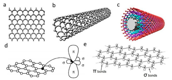
Figure 1. Schematic illustrations of the structures of (a) graphene, (b) single-walled carbon nanotube and (c) multi-walled carbon nanotube. (d) σ and π orbitals in carbon sp2 honeycomb lattice [52]; (e) overlapping sigma bonds in sp2 array of single-layer graphene. Reproduced with permission from Jorio et al., Advanced Materials, published by Wiley-VCH, 2011.
2.1. Graphene
Discovered in 2004, single-layer graphene is an atomically thin film of carbon atoms bonded together in a planar 2D structure. As illustrated in Figure 1d,e, each carbon atoms are sp2 (planar) hybridized having covalent σ bonds with three nearest carbon atoms, forming a robust honeycomb lattice. This makes graphene currently the strongest known material with Young’s modulus of ~1.0 TPa [53]. Moreover, the exceptional light absorption properties make graphene a promising candidate for phototransistors with high responsivity and sensitivity [54].
2.1.1. Electrical Properties
The ambipolar field effect on few-layers graphene, which corresponds to the availability of carriers to be tuned continuously between holes and electrons by supplying the required gate bias, was first observed by Novoselov et al. [55]. For positive gate bias, the Fermi level rises above the Dirac point, hence promoting electrons into the conduction band. On the contrary, the Fermi level drops below the Dirac point under negative gate bias, thus introducing holes into the valence band [56].
Besides the ambipolar field effect, graphene also shows the quantum Hall effect (QHE) and an extremely high carrier mobility [57,58,59,60,61,62,63,64]. As a 2D material with zero bandgaps, the electrons in graphene will be confined, leading to a quantum mechanically enhanced transport phenomena, known as QHE. However, the QHE in graphene is half-integer QHE instead of integer QHE, which is different than what is usually observed in conventional semiconductors [57]. This difference is attributed to the unique electronic properties of graphene that exhibits electron-hole degeneracy and massless Dirac fermions [57,65]. The observable QHE even at room temperature further indicates the extreme electronic quality of graphene [66].
This extraordinary electronic property is caused by the high quality of its 2D crystal lattice. In other words, graphene with higher defects density will have lower carrier mobility, since these defects act as the scattering centers, which inhibit charge transport [56]. Perpendicular to the graphene plane are the π-bonds that form delocalized electron states across the plane. Due to the easy movement of electrons in these π-states, high carrier mobility of ~200,000 cm2 V−1s−1 has been attained for suspended graphene and ~500,000 cm2 V−1s−1 for graphene-based field-effect transistor [63,64,67]. Consequently, the charge transport at such high value of carrier mobility is essentially ballistic on the micrometer scale, at room temperature [56], making graphene a useful material for biosensing and biomedical applications [68].
2.1.2. Materials Synthesis
Graphene can be produced by using top-down and bottom-up synthesis methods. Top-down synthesis methods of graphene are generally detachment or exfoliation from existing graphite crystals [69]. Exfoliation can be done mechanically (Scotch Tape method) [70], in liquid phase, exploiting ultrasounds to graphite or graphite oxide sheets by using chemicals with matching surface energy [67,71,72,73], or by electrical arc-discharge between two graphitic electrodes (Figure 2) [74].
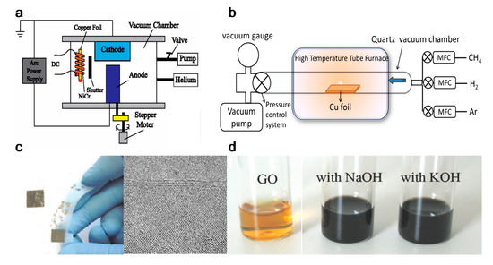
Figure 2. Graphene top-down synthesis methods. Schematic of (a) arc discharge [75] and (b) chemical vapour deposition (CVD) setup [76]; (c) micromechanical exfoliation of graphite [77] and TEM image [78]; (d) the deoxygenation of exfoliated graphene oxide (GO) under alkaline conditions [79]. Reproduced with permission from Fan et al., Journal of Applied Physics, published by American Institute of Physics, 2015; Kumar and Lee, Advances in Graphene Science, published by Books on Demand, 2013; Singh et al., Progress in Materials Science, published by Elsevier, 2011; Meyer et al., Nature, published by Nature, 2007; and Fan et al., Advanced Materials, published by Wiley-VCH, 2008.
Mechanical exfoliation (repeated peeling), the first reported approach for graphene fabrication, was initially described by Novoselov et al. [55]. Moreover, the electrical field effect of single-layered graphene from the mechanical exfoliation of small mesas of highly oriented pyrolytic graphite was also observed [55].
Liquid-phase exfoliation (LPE) is another synthesis method being characterized by its low cost, ease of operation and minimal environmental impact. Manna et al. demonstrated single- and few-layers of graphene nanosheets synthesis from bulk materials by a surfactant-free LPE, using water as the co-solvent with N-methylpyrrolidinone (NMP) [73]. Authors proved that interactions in both solid–solvent and solvent–solvent interactions could influence the LPE process [72]. Layered-materials (solid) and solvent system (liquid) interaction improves the exfoliation efficiency by minimizing solid–liquid interfacial energy (γsl), maximizing solid–liquid interfacial work of adhesion (Wsl) at the optical mw. Moreover the water–NMP (liquid–liquid) heteroassociation prevents the recombination of exfoliated layers, and the bulky (NMP·2H2O)n aggregates are able to provide intersheet repulsive forces, separating the nanosheets with non-overlapping Leonard–Jones (L–J) potentials. Briefly, 50 mg of bulk materials were placed in 14 mL centrifuge tubes with an initial concentration of 5 mg/mL for exfoliation. The materials were batch sonicated for 6 h at the power of 100 W and a frequency of 37 kHz. Every 30 min, the positions of each sample tubes were changed to achieve uniform power distribution and the water of bath sonicator was replaced to maintain the temperature between 27 and 37 °C during the sonication process. The dispersions were stored overnight and centrifuged at 3000 rpm for 30 min. According to TEM measurement, the lateral size of the exfoliated graphene was 500–2000 nm, the optimal water–NMP mixed solvent mass fraction was 0.2–0.3, which result to 0.43 (~8.6% by mass) mg/mL of exfoliated graphene nanosheets [72]. However, limited scalability, controllability and size of graphene or other 2D materials are the main limitations in the LPE process [80].
Oxidation-reduction (redox) is another top-down synthesis method. GOs produced by Hummers method can be reduced into graphene with different kinds of reducing agents, such as N2H4 and NaBH4 [80,81]. Nevertheless, the Hummers method suffers from some drawbacks, including high oxidants consumption, inevitable intercalating agents, long process time, high cost and poor scalability [82]. Schniepp et al. utilized a different approach to produce single layer graphene sheets [83], based on a redox method combined with thermal treatment, which mainly attributed to the interstices between the graphene sheets due to the CO2 expansion during rapid heating of GOs. Therefore, complete graphite oxidation and extremely rapid heating of GOs are fundamentally required. Briefly, natural flake graphite was oxidized in a mixture solution of sulfuric acid, nitric acid and KClO3 for more than 96 h. After the 0.34 nm intergraphene spacing disappears, and a new spacing of 0.65–0.75 nm range appears (depend on GOs water content), the GOs are dried and purged with argon for thermal exfoliation. The rapid heating rate of 2000 °C/min to 1050 °C would split the GOs into several individual sheets through CO2 evolution. Successful exfoliation was confirmed when all diffraction peaks were eliminated. Atomic force microscopy (AFM) measurements show that the produced graphene sheets are well dispersed at an average density of about 50 flakes per 100 μm2 and exhibit a lateral extent of a few hundred nanometers. The representative height varies at two length scales, 2 nm for the flat areas with respect to HOPG and 10 nm for the several large, meandering wrinkles [83].
On the other hand, bottom-up synthesis deal with directly growing graphene layers on substrate surfaces. This method includes epitaxial growth on silicon carbide crystal and chemical vapour deposition (CVD) where graphene from a hydrocarbon source precipitates from the transition metal surface [84,85]. Synthesis through CVD is the most viable method in terms of operational control, complexity and throughput [69].
Due to the ease of controllability and scalability, graphene films with large area and high quality can be obtained via CVD process [86]. Figure 3a–c shows a typical CVD process, which involves the deposition of volatile precursors on the exposed substrate surface to produce the desired graphene or 2D materials films. Depending on the substrate’s catalytic ability, the growth of graphene is governed by two instances: heterogeneous catalysis (governs the growth process for substrates with high catalytic ability) and gas reaction (governs the growth process for substrates with low catalytic ability). Heterogeneous catalysis is more suitable for high-quality graphene films fabrication [87]. Therefore, the key parameters in the CVD process are the catalyst, precursor, flow rate, temperature, pressure and time.
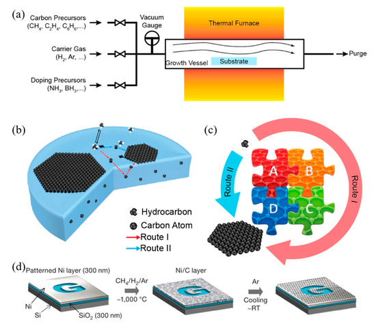
Figure 3. (a) Sketch drawing of typical CVD system for graphene fabrication; (b) elementary steps involved in CVD process (red arrow represents good metal to carbon affinity, while blue arrow represents poor metal to carbon affinity); (c) schematic illustration of four elementary steps connected together and coexistence of two routes for carbon precursors conversion to graphene [88]; (d) example of CVD synthesis of patterned graphene films on thin nickel films [89]. Reproduced with permission from Yan et al., Accounts of Chemical Research, published by American Chemical Society, 2013; and Kim et al., Nature, published by Nature, 2009.
The graphene growth on the metal substrate based on heterogeneous catalysis CVD process consists of four steps:
-
Adsorption and catalytic decomposition of precursor gas.
-
Diffusion and dissolution of decomposed carbon species on the surface and into the bulk metal.
-
Segregation of dissolved carbon atoms onto the metal surface.
-
Surface nucleation and growth of graphene.
Another different route occurs for metal with poor carbon affinity (e.g., Cu), in which the decomposition of carbon precursors was directly followed by graphene formation, realized by diffusion of carbon atoms on the metal surface. These two routes coexist in all graphene CVD system, but dominant depends on the properties of metal substrates [88].
Somani et al. reported that few-layered graphene could be obtained by CVD synthesis on nickel sheets [90]. Similarly, Kim et al. reported that graphene obtained by CVD synthesis on thin nickel films yielded good electronic properties comparable to exfoliated graphene. Briefly, as shown in Figure 3d, an electron-beam evaporator deposit thin layers of nickel with a thickness larger than 300 nm on SiO2/Si substrates. The samples were heated to 1000 °C in a quartz tube under an argon atmosphere. After flowing the reaction gas mixtures (CH4:H2:Ar = 50:65:200 standard cubic centimeters per minute (sccm) ), the samples were rapidly cooled to room temperature (~10 °C/s), using flowing argon, which is essential to prevent the multi-layers formation and efficiently separate graphene layers in the later process [89]. Li et al. also utilized copper foils as a catalytic substrate to improve graphene layer homogeneity with >95% consisted of a single layer [91].
Different synthesis methods significantly affect the properties of graphene such as surface area, number of layers, lateral dimension, surface chemistry, hydrophilicity and purity. These parameters also have an impact on the biological effects of graphene [92]. It is reported that with the decrease of lateral size of graphene nanosheets, the viability of bacteria is also decreased [93]. Besides the C/O ratio (for GO), structural defects, dopants and metallic residues also influence the biological properties of the produced graphene scaffolds [94,95].
2.1.3. Tissue Engineering Applications
After production, graphene can be reformed into zero-dimensional nanomaterial, rolled into one-dimensional nanotube or manipulated into 3D graphite [51]. Dispersed graphene and graphene oxide (GO) and its interaction with target cells have been explored [96,97,98]. Multiple reports have indicated that graphene is an outstanding platform for promoting the adhesion, proliferation and differentiation of different cell types, such as mesenchymal stem cells (MSCs), neural stem cells (NSCs), embryonic stem cells (ESCs) and induced pluripotent stem cells (iPSCs) [99,100,101,102]. In the case of neural cells, graphene was found to be capable of forming a functional neural network as demonstrated by Serrano et al. where GO 3D scaffolds were fabricated through a biocompatible freeze-casting process named ice segregation-induced self-assembly (ISISA) [103]. Positive results, such as improved neural network interconnection and an increase in dendrites, axons and synaptic connections, were observed. Graphene also has great potential for neural interfacing, promoting the neurite sprouting and outgrowth of hippocampal neurons in primary culture [100]. Heo et al. investigated neural cell-to-cell interactive reactions on graphene/poly (ethylene terephthalate) films with SHSY5Y human neuroblastoma cells, followed by electrical stimulation at low and high magnitude [101]. As shown in Figure 4, cell-to-cell interactions can be classified into either cell-to-cell decoupling (CD) or cell-to-cell coupling (CC). Furthermore, the CC group can be divided into newly formed cell-to-cell coupling (NCC) and strengthened cell-to-cell coupling (SCC). Cell-to-cell wavering (CW) was also covered. Low electrical field stimulation (4.5 mV/mm), resulted in the highest percentage of CC effect, including NCC and SCC. With high electrical field stimulation (450 mV/mm), the main reaction of cells was CD and CW. These results show that cell-to-cell decoupling is enhanced under high stimulation, while non-contact weak electric field stimulation also enables cell-to-cell coupling without cellular death [101].
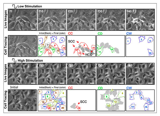
Figure 4. Representative images and analysis of cellular response to electrical stimulation; “f1” to “f40” corresponds to the 1st to 40th image taken during stimulation, using an optical microscope; “f1” cell shapes are outlined in black. The final shapes are then represented by different colors (red for cell-to-cell coupling (CC), green for cell-to-cell decoupling (CD) and blue for cell-to-cell wavering (CW)). (Top, low stimulation) Stimulation at 4.5 mV/mm where CC categorization was observed in the majority of the cells, also with clear newly formed cell-to-cell coupling (NCC) and strengthened cell-to-cell coupling (SCC). (Bottom, high stimulation) Stimulation at 450 mV/mm, where CD and CW categorized cells are more evident. Scale bar represents 30 mm [101]. Reproduced with permission from Heo et al., Biomaterials, published by Elsevier, 2011.
Tang et al. examined the development of neural network from human neural stem cells (hNSCs) differentiation at graphene by comparing fluorescence images from day 1 to day 14 [104]. After seeding, it was possible to observe that the cells were able to adhere to the substrates. As indicated in Figure 5a–d, one day after cell seeding, cells are able to migrate, to different directions from neurospheres. After 14 days, high portions of the neurites contacted each other resulting in subsequent synapse formation. A study comparing cell differentiation on glass and graphene substrates was also conducted by Feng et al. [102]. As shown in Figure 5e–h, after one month, higher hNSCs adhesion and differentiation were observed with graphene substrate. The results show that the differentiation of hNSCs more toward to neuron than glial cells, and graphene functioned as a good cell adhesion layer during the long term differentiation process [105].
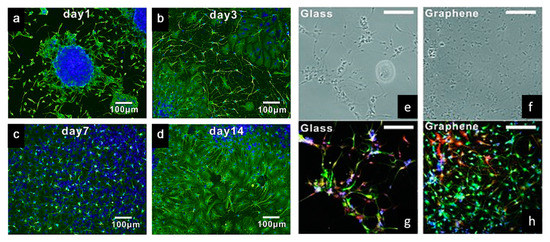
Figure 5. (a–d) Immunostaining (B-tubulin) of hNSCs differentiation developing neural networks on graphene substrates [104]. (e,f) Bright-field and (g,h) fluorescence microscopy images of immunostained differentiated hNSCs on glass and graphene substrates, after one month of cell culture. DAPI (blue) for nuclei, TUJ1 (green) for neural cells and GFAP (red) for astroglial cells [105]. Reproduced with permission from Tang et al., Biomaterials, published by Elsevier, 2013; and Park et al., Advanced Materials, published by Wiley-VCH, 2011.
Jakus et al. prepared a custom-sized nerve conduit based on graphene and poly (lactide-co-glycolide) (PLG), using an extrusion-based additive manufacturing technology [106]. Results show that by increasing the graphene concentration from 20 vol.% (or ~32 wt.%) to 60 vol.% (or ~75 wt.%), strain decreased from 210% to 81%, and conductivity increased from 200 to 600 S/m, increasing also hMSCs proliferation. Moreover, it was also observed that the expressions of certain neuronal-specific markers such as glial fibrillary acidic protein (GFAP), neuron-specific class III β-tubulin (Tuj1) and microtubule-associated protein 2 (MAP2) significantly increased after 14 days of cell differentiation [106].
Zhang et al. developed an approach which successfully added graphene into regenerated silk fibroin (RSF) scaffolds. As Figure 6 shows, biological evaluation of SCs and PC12 cells shows that the fabricated scaffolds, with the lowest resistance of 54.9 ± 20.3 Ω/sq., can effectively promote the attachment, proliferation and differentiation of the cells. The neurite growth of PC12 cells can also be simulated by the scaffolds [107]. Zhao et al. [108] and Yang et al. [109] also evaluated the graphene/silk fibroin (SF) conductive fibrous scaffolds fabricated by electrospinning. The results show that scaffolds with higher graphene concentrations exhibited higher currents and thus, higher conductivity [108]. However, the graphene concentration higher than 3 wt.% shows negative effects on cell proliferation [109].
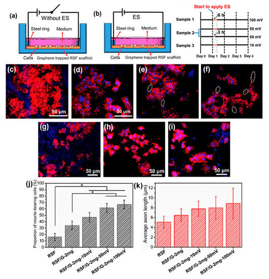
Figure 6. (a,b) Schematic representation of the cell culture device (a) without electrical stimulation (ES) and (b) with ES. The right-hand side of (b) shows the ES experimental design, where black lines indicate periods without ES, and yellow lines indicate periods with ES. (c–f) Representative laser scanning confocal microscope images of PC12 cells cultured on (c) regenerated silk fibroin (RSF), (d) RSF/G-1mg, (e) RSF/G-2mg and (f) RSF/G-4mg for four days, without ES (white ellipses indicate axons). (g–j) Laser scanning confocal microscope images of PC12 cells cultured on RSF/G-2mg scaffolds for four days with voltages of (g) 10 mV, (h) 50 mV and (i) 100 mV. (j) The proportion of PC12 neurite-bearing cells. (k) Average axon length of PC12 cells with and without ES (* p < 0.05). (g–k) ES time is 6 h [107]. Reproduced with permission from Zhang et al., Carbon, published by Elsevier, 2019.
For bone tissue engineering applications, Wang et al. [110,111,112,113] explored the use of an extrusion-based additive manufacturing system to produce poly(ε-caprolactone) (PCL)/graphene scaffolds. The effect of adding graphene to the polymeric scaffolds was studied form a morphological, physiochemical and biological point (Figure 7). Results show that the addition of small quantities of graphene has a positive impact in terms of mechanical properties, cytocompatibility and stimulating cell proliferation. PCL/graphene scaffolds with a squared pore size of 350 µm were produced by using a screw-assisted extrusion additive manufacturing system. The results show that by increasing the graphene content from 0 to 0.78 wt.%, the compression modulus increased from 82.2 ± 6.8 MPa to 128.7 ± 6.9 MPa. Cell proliferation of human adipose-derived stem cells (hADSCs) was also significantly increased due to the presence of graphene. Other studies also show that graphene can be used to accelerate the osteogenic differentiation of hADSCs [114,115].
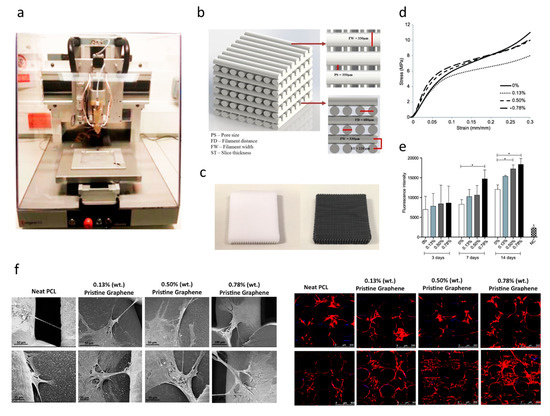
Figure 7. (a) Extrusion-based additive manufacturing system; (b) design of the PCL and PCL/ graphene scaffolds; (c) PCL and PCL/graphene scaffolds after fabrication; (d) mechanical characterization; (e) biological characterization (Alamar Blue assay); (f) scanning electron microscopy (SEM, left) and confocal microscopy images (right) of cell-seeded scaffolds [110,111,112]. Reproduced with permission from Wang et al., International Journal of Bioprinting, published by Whioce Publishing Pte. Ltd., 2016; Materials, published by MDPI, 2016; and 2nd International Conference on Progress in Additive Manufacturing, published by Research Publishing, 2016.
Further in vivo investigations were conducted based on a male Wistar rats’ model [32,116]. Six testing groups were considered: NBR (natural bone regeneration), NBR+ES (natural bone regeneration with electrical stimulation), PCL (PCL scaffolds), PCL+ES (PCL scaffolds with electrical stimulation), PCL/G (PCL composite scaffolds containing 0.78 wt.% of graphene) and PCL/G+ES group (PCL composite scaffolds containing 0.78 wt.% of graphene with electrical stimulation) as shown in Figure 8. Results show that the scaffold-based strategy, especially scaffolds containing graphene and combined with electrical stimulation, present better results in terms of bone regeneration than the natural bone repair (NBR) group. After 60 days of implantation, scaffolds containing graphene promoted higher connective tissue formation and bone mineralized tissue formation than NBR group and PCL group. Additionally, PCL+ES (31% of cumulative tissue formation), PCL/G (38.2%) and PCL/G+ES (41.2%) allowed for more new-formed tissue than the NBR group (17.6%) (Figure 8). After 120 days of implantation, the applied electrical stimulation allows for high levels of new and more organized bone formation.
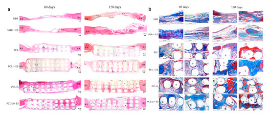
Figure 8. Photomicrography of the defect area after 60 and 120 days of in vivo bone regeneration test. (a) Attained with hematoxylin and eosin at 50× g magnification. (b) Stained with Masson Trichrome at 100× g magnification showing areas of the bone defect. In these images, it is possible to observe the bone edge (B.E), scaffold (S), connective tissue (C.T), bone tissue (B.T), graphene nanosheets (*) and matured/organized tissue (O.T) [32]. Reproduced with permission from Wang et al., Materials Science and Engineering: C, published by Elsevier, 2019.
Hou et al. proposed a novel concept of dual-functional scaffold (Figure 9) for both bone cancer treatment and bone regeneration, using graphene and GO fillers [117,118]. The scaffolds were produced by using screw-assisted extrusion-based additive manufacturing system with PCL as the polymeric matrix. Experimental results showed that the addition of both graphene and GO enhances the mechanical properties of PCL scaffolds, allowing to obtain scaffolds with compressive modulus in the same order of magnitude as human trabecular bone. In vitro biological studies were conducted, using both hADSCs and bone cancer cells Saos-2. Results show that scaffolds with GO fillers showed greater inhibition ability than scaffolds with graphene fillers. Furthermore, scaffolds containing high dose (5, 7 and 9 wt.%) of graphene showed greater inhibition ability on Saos-2 cells than hADSCs.
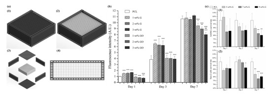
Figure 9. (a) Schematic drawing of dual-functional scaffolds including overall view (with (a1) and without top (a2), exploded view (a3) and side view (a4)). (b) In vitro cell viability/proliferation results of PCL/graphene and PCL/GO scaffolds with hADSCs. (c) Comparison test on PCL/graphene scaffold using hADSCs (c1) and Saos-2 cells (c2) [117,118]. Reproduced with permission from Hou et al., International Journal of Bioprinting, published by Whioce Publishing Pte. Ltd., 2020; and 3D Printing and Additive Manufacturing, published by Mary Ann Liebert Inc., 2020.
For cartilage tissue engineering applications, Liao et al. [119] fabricated scaffolds composed of chondroitin sulfate methacryloyl, poly(ethylene glycol) (PEG) methyl ether-ε-caprolactone-acryloyl chloride and graphene oxide (CSMA/PECA/GO), using a thermal-initiated free-radical polymerization method. In vitro biological assessments suggested that the seeded chondrocytes were able to attach proliferate. Moreover, for the in vivo biological assessment on osteochondral defects of a rabbit model, compared to the scaffold without cells, scaffolds with cell injection induced higher volume of newly formed cartilage/bone tissues [119].
Hitscherich et al. investigated the potential of PCL/graphene scaffold for cardiac tissue engineering applications. The scaffolds were prepared through electrospinning considering different graphene concentrations (0.01% and 0.5%). Electrical stimulation results show that the impedance of the scaffolds decreased by increasing the graphene contents. In vitro studies indicate that the fabricated scaffolds were biocompatible, able to support stem cell-derived cardiomyocytes, and to improve the Ca2+ handling properties of mouse embryonic stem cell derived cardiomyocytes (mES-CM). This can be explained by the local conductive pathways of the scaffolds which facilitated signal propagation and interaction between cells [120]. Bahrami et al. reported that three-dimensional graphene foams, produced by using a CVD method, could reach an electrical conductivity of 9 S/cm−1, thus stimulating a high level of the cardiac-specific genes Conx43 and TrpT-2 after seven days of cell seeding without the use of external electrical stimulation [121].
Additional biological studies using graphene electro-active structures are summarized in Table 2. However, further research is still required. The cytotoxicity introduced from graphene into these substrates is still under investigation. Research reported layered graphene sheets up to 5 μm in lateral dimension can be internalized by macrophages by adhering initially, gradually spreading and covering few-layered graphene (FLG) surface, without perturbation of their plate-like shape (Figure 10). As featured by Liao et al. [97], using human erythrocytes and skin fibroblasts, further modifying size, shape and surface chemistry of graphene, can highly influence the cytotoxicity. In addition, cover the graphene surface with biocompatible polymers can be regarded as a common method to reduce the cytotoxicity, this can also improve the solubility, stability and retention time in the blood stream [98]. Furthermore, graphene cytotoxicity is also closely associated with the biocompatibility of its surface functionalization, non-functionalized counterparts were found to be more toxic [122]. However, longer term studies need to be conducted, such as preclinical studies considering different animal models [96].
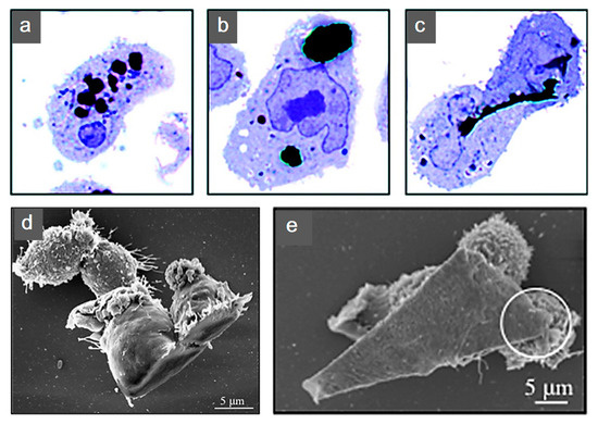
Figure 10. Human THP-1 macrophages internalization of few-layered graphene (FLG). Untreated cells were exposed to (a) 550 nm, (b) 800 nm and (c) 5 μm FLG sizes. For interaction to become more apparent under light microscopy, cells were stained with blue. (d,e) Macrophage interaction with FLG [140]. Reproduced with permission from Sanchez et al., Chemical Research in Toxicology, published by American Chemical Society, 2011.
Table 2. Studies using graphene electro-active structures.
| Electro-Active Structures | Electrical Stimulation Settings | Cell Line | Outcome | Reference |
|---|---|---|---|---|
| Cellulose/graphene scaffold | 100 mV/mm of DC for 1 h/day | Human adipose stem cells | Increased proliferation, mineral deposition and ALP expression | Li et al., 2020 [123] |
| Reduced graphene oxide-coated ApF/poly(l-lactide-co-ε-caprolactone) scaffold | 100 mV/cm for 1 h/day | SCs and PC12 cells | Promoted SC migration, proliferation, myelin gene expression, neurotrophin secretion and induced PC12 cell differentiation | Wang et al., 2019 [124] |
| Polypyrrole/graphene nanofibrous scaffold | Forward potential varied from 0.1 to 1 V/cm while reverse potential changed from −0.1 to −1 V/cm | Retinal ganglion cells | led to 137% improvement in cell length with a significantly enhanced antiaging effect for RGCs | Yan et al., 2016 [125] |
| Graphene scaffold | Square waveform with 1 Hz and 10 μA for 30 min/day | Human Rett-derived neuronal progenitor cells | Improved cell maturation | Nguyen et al., 2018 [126] |
| Graphene membrane | Intensity of 100 mV/mm with 1 ms duration at 10 or 1 Hz | PC-12 nerve Cell | Promoted neurite extension and length growth | Meng et al., 2014 [127] |
| Graphene membrane | Pulse of 15 V, duration 50–100 ms | C2C12 Myoblasts | High degree of myogenic differentiation | Bajaj et al., 2014 [128] |
| Bacterial Cellulose/Poly(3,4-ethylenedioxythiophene) (PEDOT)/GO membrane | 0.5 V cm−1 for 1–100 ms lower than 0.6 V | PC12 neural cells | Promoted cell orientation and development of PC12 cells | Chen et al., 2016 [129] |
| Graphene-based membrane | 8 V at 1 Hz with 10 ms duration | Mouse C2C12 myoblast cells | Enhanced differentiation of skeletal muscle cells | Ahadian et al., 2014 [130] |
| Methoxy PEG/rGO membrane | 1–100 ms monophasic anodic pulses, 10 s duration, 0.6 V pulse potential | PC12 neural cells | Predominant increase in cell percentage with higher action potentials | Zhang et al., 2014 [131] |
| Poly(lactic-co-glycolic acid) (PLGA)/GO membrane | 100 mV at 20, 100 and 500 Hz for 1 h/day | Neural stem cells | Promoted proliferation, differentiation and neurite elongation in NSCs | Fu et al., 2019 [132] |
| Rolled GO foam | 100 ms cathodic voltage pulses | Human neural stem cells | More proliferation of hNSCs and their accelerated differentiation into neurons | Akhavan et al., 2016 [133] |
| Graphene-based foam | −0.2–0.8 V, 1–100 ms monophasic cathodic pulses at 10 s intervals, 20–30 μA threshold | Neural stem cell | Supported cell growth and enhanced differentiation to neurons than astrocytes | Li et al., 2013 [134] |
| Graphene-based substrate | 0.3 V at 1 Hz | Human mesenchymal stem cells | Did not create a cytotoxic environment | Balikov et al., 2016 [135] |
| Graphene-based substrate | 100 mV at 50 Hz for 10 min/day | Mesenchymal stem cells | Transdifferentiation of MSCs to SC-like phenotypes solely without the need for additional chemical growth factors | Das et al., 2017 [136] |
| Graphene/polyacrylamide hydrogel membrane | 5 V with 10 ms duration at 1 Hz for 4 h/day | Mouse C2C12 myoblast cells | Increased myogenic gene expression levels of myoblasts | Jo et al., 2017 [137] |
| CS/oxidized hydroxyethyl cellulose/rGO/asiaticoside liposome-based hydrogel membrane | 250 mV for 8 h | RSC 96 cells, PC12 cells, NIH/3 T3 cells | Promoted nerve regeneration | Zheng et al., 2019 [138] |
| Graphene crosslinked collagen cryogel membrane | 1 V for 5 min at 0.20 V/mm | BM-MSCs | Promoted proliferation of cells, aiding neural connections establishment, increase immune-modulatory secretions | Agarwal et al., 2021 [139] |
This entry is adapted from the peer-reviewed paper 10.3390/polym12122946