Logic gates are devices used to perform binary arithmetic and logical operations and thus constitute the basis of modern computers. They perform Boolean logic operations on one or more inputs to produce an output. Molecular switches convert input stimulations into output signals. Therefore, the principles of binary logic can be applied to the signal transduction operated by molecular switches. The presence of various ions, neutral species, pH, temperature, and viscosity, among many others, result in color or emission changes due to the complex interplay of many excited state processes and environmental parameters. In this entry, basic logic gates are defined, and their types are given, while examples of molecular logic gates are also presented.
- molecular logic gate
- logic gates
- logical operators
1. Molecular Logic Gates
Logic gates are devices used to perform binary arithmetic and logical operations and thus constitute the basis of modern computers. They perform Boolean logic operations on one or more inputs to produce an output. Each type of logic gate possesses a specific input–output signal correlation pattern described in the so-called truth table. Truth tables list all possible combinations of input–output states. Molecular switches convert input stimulations into output signals. Therefore, the principles of binary logic can be applied to the signal transduction operated by molecular switches. It is not necessary for the inputs and outputs to share the same logic convention. Consequently, different conventions applied to the same molecular device can lead to different logic functions.[1] Various logic functions such as YES, NOT, AND, OR, NOR, NAND, INHIBIT, and XOR, were discovered and they processed the truth or falsity of one or two statements in characteristic ways.
The use of logic functions in electronic devices in general and computers in particular, really got the public’s attention. When logic functions are manifested as material objects, they are logic gates. The realization of information processing and computation at the molecular level was first recognized by de Silva et al. in 1993.[2] Scientists then started making efforts to simulate the workings of the fundamental components of integrated circuits using molecules. The molecular-level emulation of Boolean logic gates was of crucial importance in the development of molecular computation. Spinning-off from chemosensor research, molecular logic gates quickly proved themselves to be more than intellectual exercises and are now poised for many potential practical applications.[3][4]
Molecules respond to changes in their environment. The presence of various ions, neutral species, pH, temperature, and viscosity, among many others, result in color or emission changes as a result of the complex interplay of many excited state processes and environmental parameters. The diversity of fluorescent chemosensors has grown rapidly, following the works of de Silva, Czarnik, Valeur and Tsien in the 1980s who laid the foundation for the emergence of molecule-based logic gates. The clear ‘‘off–on’’ fluorescence response of Photoinduced Electron Transfer (PET) based chemosensors in response to the addition of metal ions sparked the idea of the digital action of molecules, resulting in de Silva’s milestone.[2]
In 1993, de Silva et al.[2] presented a receptor that operates as a logic device with two channels. The fluorescence signal was dependent on whether the molecule binds hydrogen ions, sodium ions, or both. The input and output characteristics of that molecular device corresponded to those of an AND gate. The receptor in this case was an anthracene derivative and, based on the ‘fluorophore-spacer1-receptor1-spacer2-receptor2’ format, was expected to fluoresce only when the tertiary amine and the benzocrown ether units were receiving proton and sodium ion input, respectively, at sufficiently high concentrations. Results showed that when both inputs were simultaneously applied, the fluorescence output rose importantly, compared to the effect of the sole presence of sodium ions or protons, respectively. Thus, the output was ‘high’ only when both sodium ions and protons were concurrent on the molecule and remained ‘low’ under the other three input signal conditions.
Supramolecular chemistry phenomena are suitable for use in molecular computation due to the fact that the dynamic and reversible interaction of a guest species with a host molecule can be considered as an input applied to a device. The output from the device would be any conveniently observable property which signals the interaction. Most phenomena of chemistry and biochemistry can be viewed as general computational operations, under the condition that resettability and speed are downgraded in importance.[3]
Computation at molecular level is possible only with the use of a molecular logic gate, which can integrate simple logic gates into combinational circuits and thus have the potential for computation on a nanometer scale. Since the first report of AND gate by de Silva, significant efforts have been made to search for molecular systems capable of mimicking the complicated functions of AND, NAND, OR, NOR, XOR, XNOR and INHIBIT logic gates based on their spectral responses towards the external stimuli such as chemical or optical inputs and generating readable output signals. A threshold value of a logic convention is established for each signal. In a positive logic convention, 0 is used to represent a signal that is below the threshold and 1 is employed to indicate a signal that is above the threshold.
These devices execute the three fundamental logic operations AND, NOT, and OR. The NOT operator converts the input signal (I) into the output signal (O). When I is 0, O is 1. When I is 1, O is 0. The OR operator combines the two input signals and into the output signal. When I1 and/or I2 is/are 1, O is 1. When I1 and I2 are 0, O is 0. The AND gate, which is a main point of interest in this thesis, also combines two inputs into one output. The simultaneous presence of both input signals is here required to obtain an output signal. Thus, O is 1 only when both inputs are 1.
More advanced logic functions can be obtained by connecting NOT, OR, and AND gates into combinational circuits and they obey different truth tables.
In general, the reported systems were based on the modulation of the emission properties of the designed molecules by different combinations of external inputs, such as light, anions, metal ions, solution pH, and solvent polarity. Relatively few molecular systems can perform multiple logic functions based on the modulation of both absorption and emission properties.[5] Most examples developed so far are based on fluorescence switching caused by photoinduced electron-transfer (PET) processes. Fluorescence is an ideal output because it is easy to detect, even at the single-molecule limit. Molecular logic gates based on electrical input/output signals are advantageous as they are compatible with microelectronic devices, at least on a qualitative level.[1]
2. Basic Logic Gates: Definition and Types
2.1. AND Gates
The AND operator has two inputs and one output in a simple electrical scheme. This can be represented by two switches in series. At the molecular scale, fluorescent sensors investigated long ago, follow an AND logic. Their logic aspect had not been recognized yet. The most common examples of molecular-level AND gates include those based on two chemical inputs and a fluorescence output. Nonetheless, examples of molecular systems able to process chemical and optical inputs or two optical inputs with AND functions are also known. AND logic is also featured in the so-called “off-on-off” (or “on-off-on”) systems. Typical examples include fluorescent sensors that detect a metal ion in only a well-defined pH range. Ion pair recognition can be viewed as an example of AND logic as well.[1]
The AND gate is an electronic circuit that gives a high output (1) only if all its inputs are high.
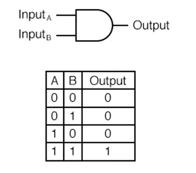
Figure 1. A two-input AND gate and its truth table.

Figure 2. Illustrations of a 2-input AND gate (left) and 3-input AND gate (right).
1.2.1. AND Gate Sample Circuit Operation
The practical meaning of this truth table is illustrated in the following sequence of figures. The 2-input AND gate is subjected to all possibilities of input logic levels.[1][6] A LED (Light-Emitting Diode) provides visual indication of the output logic level:
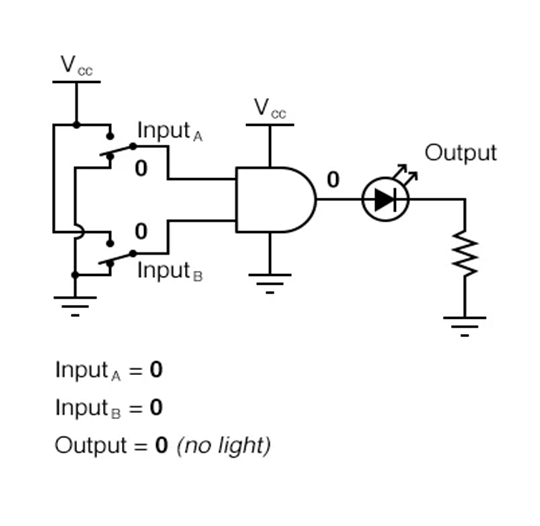
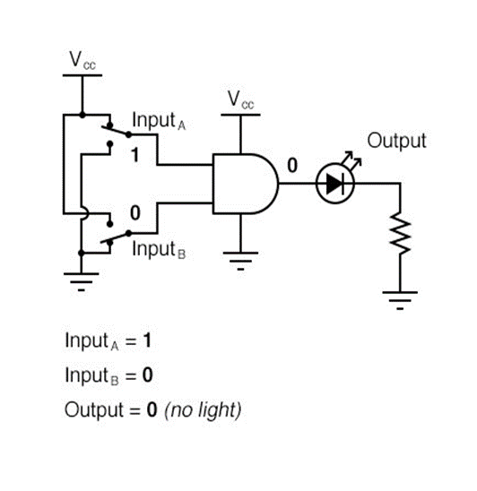
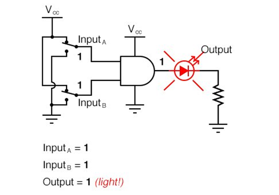
Figure 3. The function of a 2-input AND gate with all possible input and output logic levels.
1.2.2. The NOT Gate
The NOT gate is an electronic circuit that produces an inverted version of the input at its output. It converts the input signal 1 into the output signal 0, and vice versa. Because of the inverse relationship between the input and output values, the NOT gate is often called inverter.[1][6]
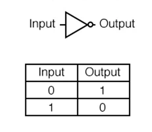
Figure 4. The NΟΤ gate with its truth table.
1.2.3. The NAND Gate
The NAND gate is a variation on the idea of the AND gate. The word “NAND” is a verbal contraction of the words NOT and AND.
A NAND gate behaves in the same manner as an AND gate with a NOT (inverter) gate connected to the output terminal. The NAND gate symbol has a bubble on the output line, stating this output signal inversion.[1][6]
The truth table for a NAND gate is the exact opposite as that of an AND gate:
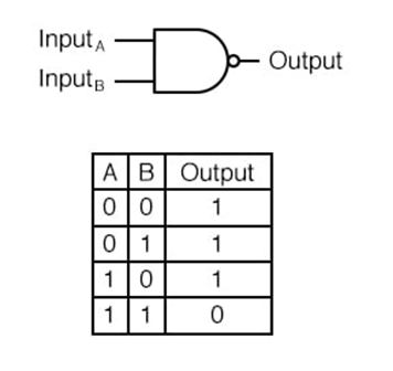
Figure 5. A 2-input NAND gate with its truth table.
NAND gates are made with more than two inputs. In such cases, the output will be “low” (0) if and only if all inputs are “high” (1). If any input is “low” (0), the output will go “high” (1).
1.2.4. The OR Gate
In the case of the OR gate, the output will be “high” (1) if any of the inputs are “high” (1). The output of an OR gate goes “low” (0) if and only if all inputs are “low” (0).[1][6]

Figure 6. Illustrations of a 2-input OR gate (left) and 3-input OR gate (right).
A two-input OR gate’s truth table has the following form:
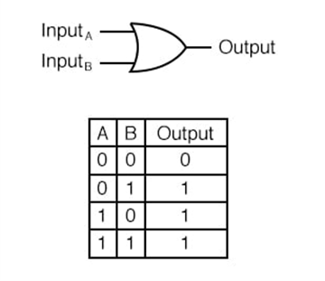
Figure 7. Α 2-input OR gate with its truth table.
OR Gate Sample Circuit Operation
The following illustrations demonstrate the function of the OR gate, with the 2-inputs experiencing all possible logic levels.[1][6] A LED (Light-Emitting Diode) provides visual indication of the gate’s output logic level:
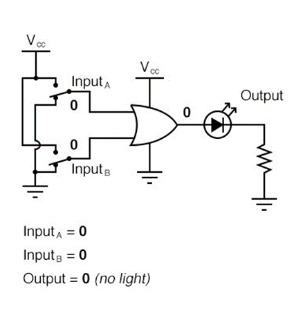
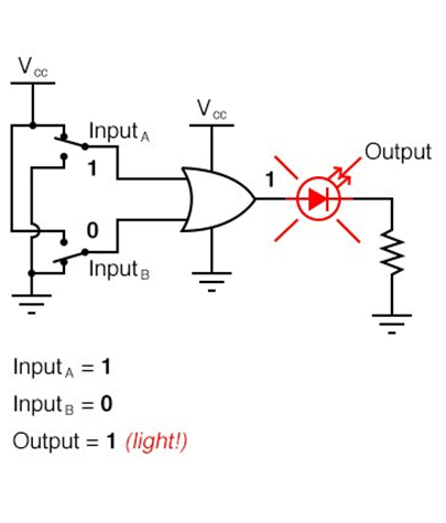
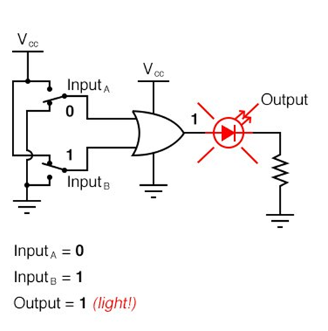
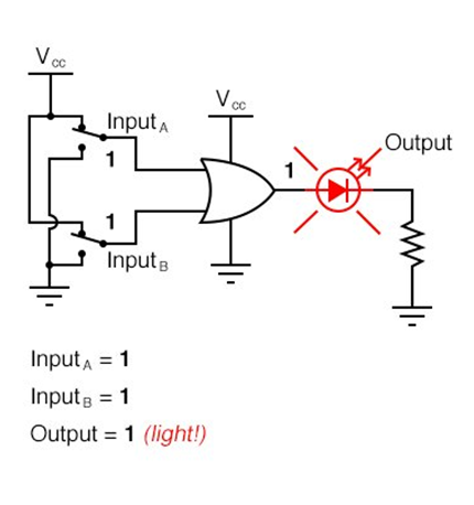
Figure 8. The function of a 2-input OR gate with all possible input and output logic levels.
1.2.5. The NOR Gate
The NOR gate is an OR gate with its output inverted, in the same way as a NAND gate is an AND gate with an inverted output.
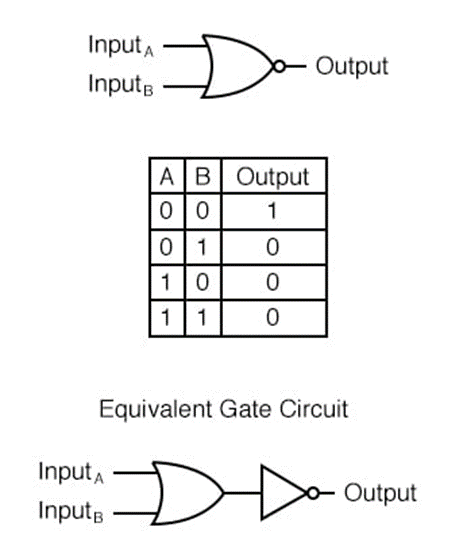
Figure 9. A 2-input NOR gate with its truth table, as well as an equivalent gate circuit.
NOR gates can also be manufactured with more than two inputs. Again, the output goes “low” (0) if any of the inputs are “high” (1). The output is “high” (1) only when all inputs are “low” (0).[1][6]
1.2.6. INHIBIT Gate
INHIBIT gates are, in fact, AND gates with one of the inputs inverted through a NOT function. At the molecular scale, integration between two such gates can be achieved by chemical design. Several examples of molecular INH gates have been described in recent years.
The INH logic features noncommutative behavior, meaning one of the inputs can disable the whole system. In the gate illustrated above, when In2 is 1 the gate provides 0 as the output, regardless of the other input.[1][6]
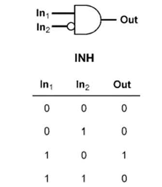
Figure 10. The INHIBIT gate with its truth table.
1.2.7. The Negative-AND Gate
A Negative-AND gate functions in the same way as an AND gate with all its inputs inverted (connected through NOT gates). These inverted inputs are signified by bubbles.[1][6]
The logical behavior of a Negative-AND gate is not the same as that of a NAND gate. Its truth table is, in fact, identical to a NOR gate:
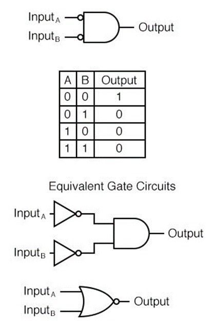
Figure 11. A 2-input Negative-AND gate with its truth table, as well as equivalent gate circuits.
1.2.8. The Negative-OR Gate
A Negative-OR gate functions in the same way as an OR gate with all its inputs inverted. These inverted inputs are signified by bubbles. A Negative-OR gate behaves the same as a NAND gate and they have the same truth table, as well.[1][6]
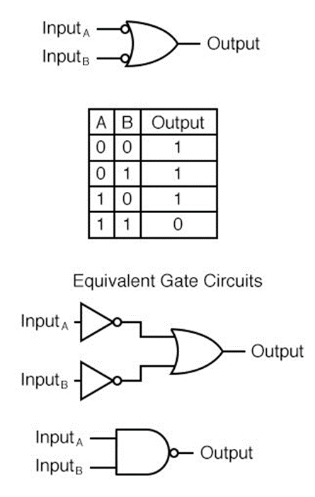
Figure 12. A 2-input Negative-OR gate with its truth table, as well as equivalent gate circuits.
1.2.9. The Exclusive-OR Gate
Exclusive-OR gates output a “high” (1) logic level if the inputs are at different logic levels. On the other hand, they output a “low” (0) logic level if the inputs are at the same logic levels. Thus, the exclusive-OR gate can compare the digital state of two signals.[1][6]
The Exclusive-OR (sometimes called XOR) gate has a symbol and a truth table pattern that are unique:
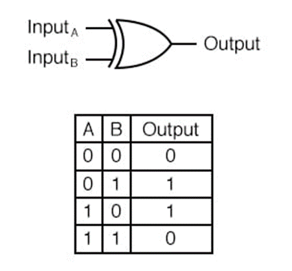
Figure 13. The Exclusive-OR gate with its truth table.
1.2.10. The Exclusive-NOR Gate
The Exclusive-NOR gate, also known as the XNOR gate, is equivalent to an Exclusive-OR gate with an inverted output. Exclusive NOR logic corresponds to an XOR gate feeding into a NOT gate.[1][6]
The truth table for this gate is the exact opposite of the corresponding one to the Exclusive-OR gate:
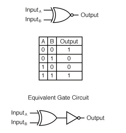
Figure 14. The Exclusive-NOR gate with its truth table.
The purpose of an Exclusive-NOR gate is to output a “high” (1) logic level whenever both inputs are at the same logic levels.
2. Examples of Molecular Logic Gates
- A molecular AND logic gate (molecule 1) was demonstrated based on the competition between fluorescence and photoinduced electron transfer (PET).[7] It is constructed according to a ‘receptor2-spacer-fluorophore-spacer-receptor1-spacer-fluorophore-spacer-receptor2’ format, where receptor1 is a tertiary amine, receptor2 is a benzo-15-crown-5 ether and the fluorophore is an anthracene moiety. They are separated from each other using methylene spacers. The fluorescence response in methanol is significantly enhanced only when both H+ and Na+ are the inputs at high enough concentrations in consistence with AND logic. Cs+ behaves similarly to Na+, but with a lower fluorescence enhancement, while the other alkali metal cations are not effective.
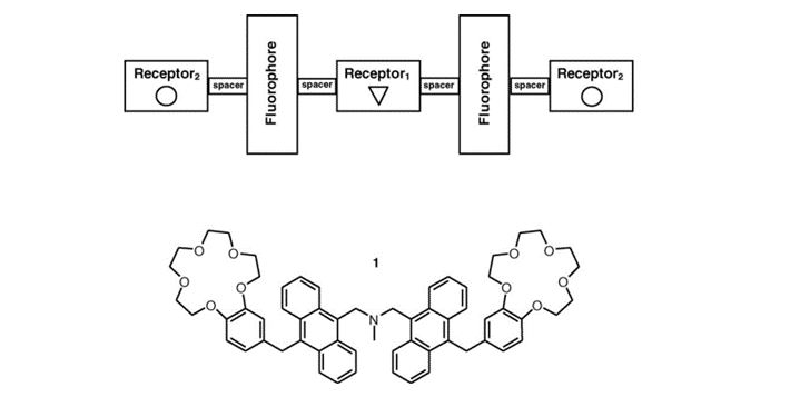
Figure 15. The modular format (top) and the molecular structure (bottom) of AND logic gate 1.
Molecule 1 was the first fluorescent PET system to employ a ‘receptor2-spacer-fluorophore-spacer-receptor1-spacer-fluorophore-spacer-receptor2’ format. The molecule is designed in such way that each receptor is capable of PET to an excited anthracene fluorophore in the absence of the analyte, knocking out the fluorescence. In this case, a tertiary amine and two benzo-15-crown-5 ether have been employed as receptors and they have served as PET donors to anthracenic fluorophores in previous studies.[2][8][9] Thus, molecule 1 will have the ability to capture H+ at the amine, and Na+ in the crown ethers. In previous studies[2][8][9], only one benzo-15-crown-5 ether was incorporated into the molecule, while in molecule 1 there are two such receptors.
- Magri’s[10] aminonaphthalimide-based logic gate 2 incorporates virtual C0-type and diethylene spacers to the benzo-15-crown-5 and methylpiperazine receptors, respectively. Heagy[11] was the one to discover good selectivity for Na+ and K+ with benzo-15-crown-5 and benzo-18-crown-6 in water. The use of Na+ and H+ in aqueous methanol led to the observation of an expected AND logic outcome. DFT calculations support enhanced crown ether binding occurs via Na+ or K+ interaction with an aminonaphthalimide carbonyl oxygen atom. PET from the dimethoxyphenyl electron donor is disrupted on increasing solvent polarity.[12] Thus, solvent-based reconfigurable logic is built into molecule 2. Green fluorescence is emitted in response to high H+ and high Na+, as well as with high H+ and low Na+. In water, the molecule functions as a single H+-driven YES gate or a two-input H+-TRANSFER logic gate. The Na+ has no effect in this case. The solvent dependent input–output characteristics correspond to a pattern of AND and INHIBIT logic gates in parallel.
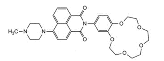
Figure 16: Molecule 2.
- Three chemical inputs instead of two, increase the logic complexity exponentially.[10] The first example of a molecule for detecting a congregation of three chemical species 3 was demonstrated in Belfast in 2006.[13] The design is based on an extension of a previous structure by attaching additional spacer and receptor modules to give a ‘receptor1–spacer1–fluorophore–spacer2–receptor2–spacer3–receptor3’ format. As a ‘lab-on-a-molecule’, it can detect for three biologically relevant analytes Na+, H+ and Zn2+ in water. The testing occurs in parallel as each receptor binds to a specific analyte in a selective way. PET from any of the three unbound receptors can quench the anthracene fluorescence centered at 436 nm.
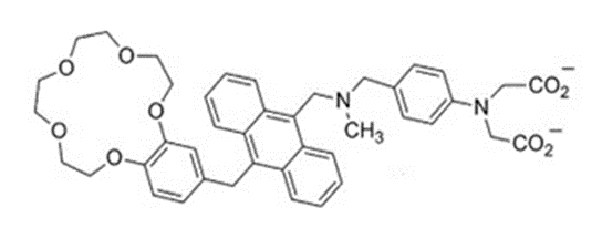
Figure 17. Molecule 3.
- Another example worth mentioning is the structure of molecule 4 now appended in molecule 5 to a boronic ester.[10] The inputs are Fe3+, sodium L-ascorbate (LAS) and F- ions. The addition of Fe3+ leads to emission at 512 nm and is observed in THF due to oxidation of the ferrocene moiety. Subsequent addition of L-absorbate acid reduces Fe3+ to Fe2+. The combination of these two inputs results in reversible off–on-off switching. The F- ion interacts with the boronic ester group to form a tetrahedral boronate anion. Two INHIBIT logic gates can be viewed with Fe3+ being the enabling input and either LAS or F- as a disabling input for turning the fluorescence off. As a three-input molecular device, the truth table corresponds to a three-input disabled INHIBIT gate.[14] The optical signal occurs when one input is ‘high’ and two inputs are ‘low’. The input triad of Fe3+, H+ and F- could illustrate three-input INHIBIT logic.[15]
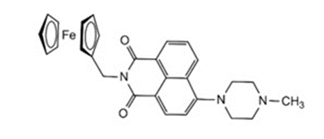
Figure 18. Molecule 4.
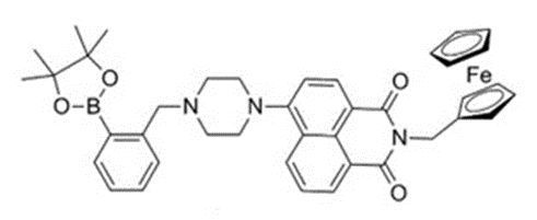
Figure 19. Molecule 5.
- A way to interpret the INHIBIT (INH) function is as a particular integration of an AND and a NOT logic functions, where one of the active inputs inhibits the output signal. It was found[16] that, in water, the Tb (III) based quinolyl derived macrocyclic 1,4,7,10-tetraazacyclododecane (cyclen) conjugate, yields such an INH logic gate. The two inputs are H+, where the nitrogen moiety of the quinoline acts as a proton acceptor, and O2 or, in fact, the absence of O2, as this input is not asserted when O2 is present. The output signal is a delayed line like Tb luminescence, occurring at long wavelengths. Sharp, long wavelength emissions give minimal signal interference, critical for high performance signaling systems. Thus, the forementioned features are important. Tb was chosen because, unlike Eu (III), pyridine-based Tb and related complexes are known to be spectroscopically sensitive to O2, opening thus the possibility of a gate with O2 as a second input. In addition, lanthanide based cyclen derivatives have been shown to be kinetically stable in water.
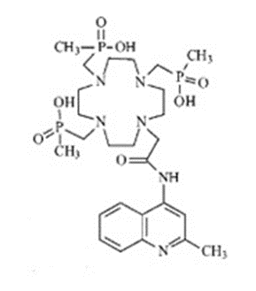
Figure 20. The free ligand in example [5].
Contrary to previous molecular logic gates where the output is a broad emission[2][8], the output signal for the molecule studied in this case is a set of line-like Tb emission bands occurring at long wavelengths with narrow bandwidth, giving rise to a high signal quality. Thus, this complex is an important contribution to the development of molecular logic devices.
- Qin et al.[17] have synthesized novel spherical polymer nanoparticles by hyperbranched polyethylenimine (hPEI) and 6-hydroxy-2- naphthaldehyde (HNA) via Schiff base reaction. This had great advantages in water solubility and green synthesis. Probe PEI-HNA can also quickly detect Cu2+, while the fluorescence of PEI-HNA-Cu2+ can be recovered by adding S2−. Based on its excellent optical properties, PEI-HNA has been used in the bioimaging of living cells with excellent cell penetrability and low toxicity. PEI-HNA has also been used to prepare solid-phase sensors, displaying rapid response and excellent sensitivity. Additionally, the low-cost and simple preparation of such sensors offer great potential and possibilities for industrial development. This could be helpful in accelerating the development of sensors in environmental and biological fields.
- Liu et al.[18] constructed a new type of nanosensor, PEIN, using Cu2+ as input 1 and cysteine (Cys) as input 2. Based on the IMPLICATION operation, the fluorescence signal of PEIN at 444 nm is changed into an output for a two-input logic gate, as illustrated below. This two-input logic gate consists of a “NOT” gate and an “OR” gate. The principle of the logic gate is that the fluorescence of PEIN at 444 nm can be quenched by Cu2+ but can be recovered after addition of the biological thiol Cys. Thus, only when the input is (1, 0) will the output be “0”. The logic gate constructed in this study can detect Cu2+ and Cys in sequence quickly.

Figure 21. The truth table corresponding to the aforementioned system.
3. Application of Molecular Logic Gates
Professor de Silva's blood pressure device: a worldwide hit
Professor A. Prasanna de Silva invented a device to help care for his grandmother, who suffered from hypertension. This device is now being used in hospitals around the world. This unique mobile sensor, devised to treat high blood pressure, has also been used in ambulances and field hospitals in trouble spots globally. The thought of the device came to de Silva in 1980, while taking care of his grandmother. The doctor caring for de Silva's grandmother explained to him how reducing sodium can reduce blood pressure. This required measuring sodium levels, which was a process done in a clinical lab that took several days. de Silva then began researching alternatives to measuring sodium, including using molecule sensors to detect sodium levels. He took his research with him to Queen's University in Belfast and constructed several sensors that communicated sodium levels by sending light signals. The sensors were much faster than traditional lab work and made blood tests available in 30 seconds. de Silva never thought to try to mass produce the sensors, but in 1998 medical supplies firm Roche Diagnostics read a research publication from Queen's, and several members visited de Silva in Belfast to see the sensors he had constructed. Roche Diagnostics then partnered with de Silva to produce the sensors, and they quickly spread all over the world. The sensors are now used in critical care units in the US and Europe, doctors' offices in Japan, army field hospitals in China, and ambulances in Sri Lanka and Libya. de Silva's work was presented to Parliament as part of a national campaign run by the Royal Society of Chemistry and Institute of Physics. de Silva believed that a modern economy like the UK's cannot be sustained in the long-term without a science foundation and that it is science achievements that remain, contrary to financial gain which comes and goes. He also remarked that those achievements, born in quiet laboratories, need commercial and political will, so that wider society can benefit.[19]
References
- Balzani, V.; Credi, A.; Venturi, M. Molecular Devices and Machines Concepts and Perspectives for the Nanoworld Second Edition; WILEY-VCH Verlag GmbH & Co. KGaA: Weinheim, Germany, 2008; pp. 259-275.
- de Silva, A. P.; Gunaratne, N. H. Q.; McCoy, C. P.; A molecular photoionic AND gate based on fluorescent signalling. Nat. 1993, 364, 42-44, .
- de Silva, A. P. Molecular Logic Gates, Supramolecular Chemistry: From Molecules to Nanomaterials; Wiley-Blackwell: Weinfeld, Germany, 2012; pp. 2497-2506.
- Erbas-Cakmak, S.; Kolemen, S.; Sedgwick, A. C.; et al.; Molecular logic gates: the past, present and future. Chem. Soc. Rev. 2018, 47, 2228-2248, .
- Mardanya, S.; Karmakar, S.; Das, S.; et al.; Anion and cation triggered modulation of optical properties of a pyridyl-imidazole receptor rigidly linked to pyrene and construction of INHIBIT, OR and XOR molecular logic gates: A combined experimental and DFT/TD-DFT investigation. Sensors Actuators B: Chem. 2015, 206, 701-713, .
- Multiple-input gates. All about circuits. Retrieved 2024-3-28
- Magri, D. C.; Coen, G. D.; Boyd, R. L.; et al.; Consolidating molecular AND logic with two chemical inputs. Anal. Chim. Acta 2006, 568, 156-160, .
- de Silva, A. P.; McClean, G. D.; Pagliari, S.; Direct detection of ion pairs by fluorescence enhancement. Chem. Commun. 2003, 16, 2010-2011, .
- de Silva, A. P.; Gunaratne, H. Q. N.; McCoy, C. P.; Molecular Photoionic AND Logic Gates with Bright Fluorescence and “Off−On” Digital Action. J. Am. Chem. Soc. 1997, 119, 7891-7892, .
- Magri, D. C.; Logical sensing with fluorescent molecular logic gates based on photoinduced electron transfer. Co-ord. Chem. Rev. 2020, 426, 213598, .
- Nandhikonda, P.; Begaye, M. P.; Heagy, M. D.; Highly water-soluble, OFF–ON, dual fluorescent probes for sodium and potassium ions. Tetrahedron Lett. 2009, 50, 2459-2461, .
- Magri, D. C.; Callan, J. F.; de Silva, A. P.; et al.; The Anthracen-9-ylmethyloxy Unit: An Underperforming Motif Within the Fluorescent PET (Photoinduced Electron Transfer) Sensing Framework. J. Fluoresc. 2005, 15, 769-775, .
- Magri, D. C.; Brown, G. J.; McClean, G. D.; et al.; Communicating Chemical Congregation: A Molecular AND Logic Gate with Three Chemical Inputs as a “Lab-on-a-Molecule” Prototype. J. Am. Chem. Soc. 2006, 128, 4950-4951, .
- Montenegro, J.-M.; Perez-Inestrosa, E.; Collado, D.; et al.; A Natural-Product-Inspired Photonic Logic Gate Based on Photoinduced Electron-Transfer-Generated Dual-Channel Fluorescence. Org. Lett. 2004, 6, 2353-2355, .
- Chen, X.; Wang, Y.; Liu, Q.; et al.; Construction of Molecular Logic Gates with a DNA‐Cleaving Deoxyribozyme. Angew. Chem. Int. Ed. 2006, 45, 1759-1762, .
- Gunnlaugsson, T.; Mac Dónail, D. A.; Parker, D.; Luminescent molecular logic gates: the two-input inhibit (INH) function. Chem. Commun. 2000, 1, 93-94, .
- Qin, X.; Tong, Q.; Chang, M.; et al.; A hydrophilic polymer-based bifunctional nanosensor for sequential fluorescence sensing of Cu2+ and biothiols and constructing molecular logic gate. J. Photochem. Photobiol. A: Chem. 2020, 402, 112792, .
- Liu, L.; Liu, P.; Ga, L.; et al.; Advances in Applications of Molecular Logic Gates. ACS Omega 2021, 6, 30189-30204, .
- de Silva 's blood pressure device. Queen's University Belfast, School of Pharmacy. Retrieved 2024-3-28
