Your browser does not fully support modern features. Please upgrade for a smoother experience.
Please note this is an old version of this entry, which may differ significantly from the current revision.
Image inpainting is sometimes called an inverse problem, and usually these types of problems are ill-posed. The problem of inpainting consists in finding the best approximation to fill in the region inside the source image and comparing it with the ground truth. All the algorithms that tackle this problem begin with the assumption that there must be some correlation between the pixels present inside the image, either from a statistical or from a geometrical perspective.
- image inpainting
- object removal detection
- forensic forgery
1. Introduction
The objective of inpainting is to minimize the difference between the original image, I, and the reconstructed image, R, in the domain, D. This is typically achieved by defining an appropriate loss function that quantifies the differences between I and R in region D. In other words, the inpainting problem can be formulated as an optimization problem that minimizes an objective function. The objective function typically consists of two main components: a term that penalizes the deviation of the inpainted values from the known values in the known region, D; and a term that penalizes large variations in the inpainted values, encouraging smoothness and preventing overfitting. Thus, the first operation ensures that the inpainted image is consistent with the available information, and the second helps to preserve the natural structure and appearance of the original image. The inpainting methods can be split into the following three categories:
-
Diffusion-based or sometimes called partial differential equations-based (here, researchers are also going to include TV methods as well);
-
Exemplar-based or patch-based, as referred to in some other papers;
-
Machine learning is undertaken irrespective of their model architecture.
The following section focuses on describing the most cited and recent state-of-the-art methods to better understand, the overall artifacts introduced in the inpainting procedure.
2. Diffusion-Based Methods
The term diffusion (from a chemistry point of view) is an action in which items inside a region of higher concentration tend to move to a lower concentration area. In the analysis undertaken in [1], in which the inpainting process is inspired by the “real” inpainting of canvas, the process consists of the following steps:
-
Global image properties enforce how to fill in the missing area;
-
The layout of the area, , is continued into D (all edges are preserved);
-
The area, D, is split into regions, and each region is filled with the color matching (the color information is preserved from the bounding area, , into the rest of the D area);
-
Texture is added.
The first step in all the inpainting algorithms is to apply some sort of regularization. It can be isotropic, with some poor results, anisotropic, or any other type of regularization. This is performed to ensure that image noise is removed, so that it shall not interfere in the computation of the structural data needed in the next step.
To apply diffusion, the structural and statistical data of the low-level image must be identified. Based on this data, if on an edge in the δD area, the algorithm must conserve the edge identified, and if the δD area belongs to a consistent area, the algorithm can then easily replicate the same pixel information from the border. To retrieve image geometry, one can use isophotes, which are curved on-surface connecting points of the same values. For this, one needs to first compute the gradient on each point in the margin area and then compute the direction as normal in relation to the discretized gradient vector.
Having performed these steps, the initial algorithm from [1] is just a succession of anisotropic filtering, followed by inpainting, and then, this is repeated several times. Later, the authors in [2] proposed an improved version of their initial algorithm. This idea was inspired from the mathematical equations of fluid dynamics, specifically the Navier–Stokes equations, which describe the motion of fluid. The proposal was to use the continuity and momentum equations of fluid dynamics to propagate information from known areas of the image towards the missing or corrupted areas. This was an improved version of the higher PDE version presented initially. As a follow-up of his original work, Bertalmio proposed the use of third-order PDE in [3], which is a better continuation of edges. At the same time, Chan and Shen developed similar algorithms [4][5], in which they postulated the use of the local curvature of an image to guide the reconstruction of missing or obscured parts. Using Euler’s elastica model, they could predict what the missing parts of an image might look like. Both Euler’s elastica and PDE-based inpainting are effective methods for image inpainting and have their own advantages and disadvantages. Euler’s elastica is particularly well-suited for images that contain thin, flexible objects, while PDE-based inpainting is well-suited for images that are smooth and locally consistent. Depending on the specific characteristics of the image and the desired outcome, one method may be more appropriate than the other. In recent year, the focus for diffusion-based inpainting has moved towards increasingly complex PDE forms; e.g., in [6] using high-order variational models is suggested, like low curvature image simplifiers or the Cahn–Hilliard equation. Another recent paper that goes in the same direction is [7], which integrates the geometric features of an image—namely the Gauss curvature. Still, even these methods introduce the blurring artifact also found in the initial papers [1][2]. To surpass these challenges in the current models, with second-order diffusion-based models that are prone to staircase effects and connectivity issues and fourth-order models that tend to exhibit speckle artifacts, a newer set of models must be developed. The authors Sridevi and Srinivas Kumar proposed several robust image inpainting models that employ fractional-order nonlinear diffusion, steered by difference curvature in their papers [8][9][10]. In their most recent paper [11], a fractional-order variational model was added to mitigate noise and blur effectively. A variation of DFT is used to consider pixel values from the whole image, and this is not by relying strictly on only the neighboring pixels.
Another method that yields better results than standard PDE is the use of total variation inpainting. The core idea is to minimize the total variation of the inpainted image, effectively reducing the abrupt changes in intensity. TV inpainting incorporates a regularization term into the optimization problem. This term typically comes in two types: L1 and L2 regularization. L1 regularization encourages sparsity in the gradients of the inpainted image, promoting piecewise constant solutions with sharp edges. On the other hand, L2 regularization results in smoother images with gradual transitions. The choice between these regularization terms determines the trade-off between smoothness and fidelity in the inpainted result. First-order TV inpainting focuses on minimizing the L1-norm of image gradients and is effective for restoring image edges and preserving fine structures. Minimizing the L1-norm of gradients encourages sparsity in the gradient domain, leading to piecewise constant solutions. One of the key advantages of first-order TV inpainting is its applicability in various scenarios, including image denoising and deblurring. This method excels in reconstructing images with well-defined edges and minimal noise. Second-order TV inpainting extends the TV concept by considering gradients of gradients, also known as the Laplacian operator. This extension allows for the preservation of more complex image structures, including textures and patterns. By considering higher-order derivatives, second-order TV inpainting can produce inpainted images with improved fidelity. However, second-order TV inpainting introduces computational challenges due to the increased complexity of the optimization problem such as in [12] where the split Bregman technique is used.
Based on the multitude of research on inpainting using PDE or TV methods, there are still some areas to be improved, and some artifacts are easily identifiable. In the following section, two methods are analyzed in terms of the artifacts introduced in the inpainting process. The first is based on the Cahn–Hilliard equation [6] and is a fourth-order PDE that describes the phase separation process in materials and has been adapted for inpainting tasks in image processing, while the second analyzed method is based on total variation [12] and uses a combined first- and second-order total variation. The first analyzed sample is presented in Figure 1: on the left side is the original image [6], and on the right is the mask applied to that image. The mask created for the PDE method is created specifically for this test, and it tries to simulate a scratch on the image. The inpainting methods will try to generate pixels that are as accurate as possible to fill in the white line.
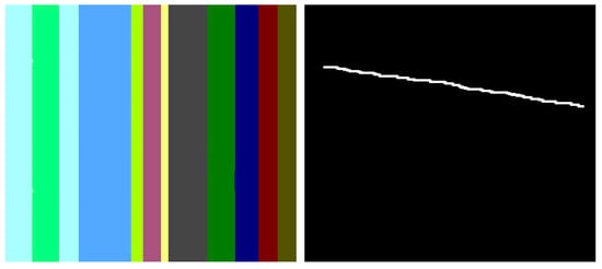
Figure 1. Original image and the applied mask.
In the below image, Figure 2, the result of the Cahn–Hilliard inpainting method can be observed. The parameters used to generate the image are the standard suggested by the authors (max iteration = 4000, epsilon = [100,1], lambda = 10).
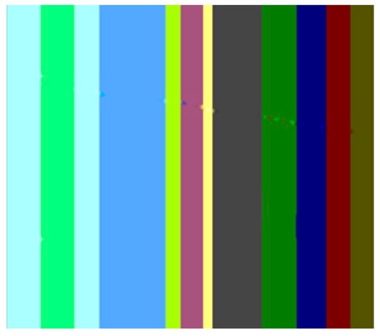
Figure 2. Image inpainted using Cahn–Hilliard.
The first artifact that can easily be distinguished is the discontinuity; e.g., when transitioning from the maya blue region to the green and yellow region. PDE methods can sometimes introduce noticeable discontinuities or abrupt transitions between inpainted regions and the surrounding image. Another noticeable artifact is the incorrect color matching as shown in Figure 3: in cases where color is not properly preserved or matched during inpainting, the inpainted regions may not blend seamlessly with the rest of the image, leading to visible differences in color or texture. This can be easily noticed in the canary color region. Another visible artifact introduced during the inpainting method is blurring because diffusion-based PDEs tend to smooth the image as they propagate information, which can lead to a loss of sharpness and detail.
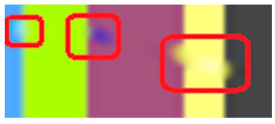
Figure 3. Zoomed area to emphasize discontinuities, incorrect color, blurring, and over smoothing.
In the above scenario, the TV variation [12] is able to correctly reconstruct pixels, at least from a human perspective. However, upon examining the pixel values with the area values, it becomes apparent that the reconstruction is not flawless, as there are minor discrepancies in colors, as shown in Figure 4.
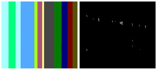
Figure 4. On the left side is the reconstructed image, and on the right side is the difference between reconstructed image and original image.
The second analyzed scenario is more complex, and researchers are going to focus on the TV method only because the classic PDE method usually struggles with larger/highly texturized areas. In Figure 5, on the left side is the original image [12], and on the right is the mask applied to that image. The inpainting methods will try to generate pixels that are as accurate as possible to fill in the white line. In the below image, the result of the TV inpainting method can be observed. The parameters used to generate the image are the standard one suggested by the authors (maxIteration = 100, Gamma1 = 5, Gamma2 = 8).
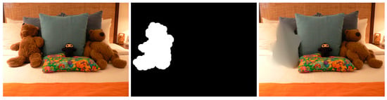
Figure 5. Original image, the applied mask, and the TV result.
Some of the above already discussed artifacts from the classic PDE method also appear in the context of the TV methods as well when the inpainting region is bigger and more complex: blurring around the area, over smoothing inside the inpainted area, and inaccurate texture matching/color matching of the water. In addition to the above artifacts, some other interesting artifacts are exhibited after using the TV methods: staircase artifacts and halos. Staircase artifacts, also known as “blocking artifacts,” are a type of visual distortion that occurs in images when there is a sharp transition or abrupt change between adjacent blocks or regions, and this can be seen in the below sample. These artifacts are characterized by the appearance of visible grid-like patterns resembling a staircase along the edges or boundaries of these blocks. This type of artifact can be observed in the zoomed area in the below picture (Figure 6).
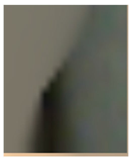
Figure 6. Staircase artifact seen in zoomed area from the above TV output.
TV inpainting methods can also introduce halos, which are bright or dark rings that appear around the edges of the inpainted region. This is more likely to occur when the inpainted region has a lot of contrast between the inpainted region and the surrounding area.
Summarizing the diffusion inpainting methods, it is found that they usually rely on second or higher order partial derivatives or the total variation of energy to be able to “guess” the missing area. One of the major drawbacks of these methods is as follows: depending on the complexity of the inpainted region, they might introduce blurring or some sort of color and texture inaccuracy, which in turn will affect the entire image. The blurring effect usually happens because of either the regularization operation or due to the diffusion process. Halos associated with TV are another cause of the tendency to over smooth edges. This over smoothing occurs because the TV minimization objective encourages the image to have constant brightness across each pixel, which can lead to abrupt changes in brightness at the edges. These abrupt changes in brightness appear as halos around the inpainted region. Due to this blurring effect, in theory, image inpainting via PDE and TV can be detected via some sort of inconsistency in the blurring effects of various regions or inconsistencies inside the color/texture, but this is harder to detect without a priori knowledge of the original image.
3. Exemplar-Based Methods
At the same time, a newer approach based on texture synthesis started to gain more momentum. The main inspiration came from [13] in which A. A. Efros and T. K. Leung introduced a non-parametric method for texture synthesis, where the algorithm generates new texture images by sampling and matching pixels from a given input texture based on their neighborhood pixels, thus effectively synthesizing textures that closely resemble the input sample. This approach was notable for its simplicity and ability to produce high-quality results, making it a foundational work in texture synthesis. The primary goal of this approach was to enhance the reconstruction of the image section area that is missing. However, the challenges brought by texture synthesis are slightly different from those presented by classic image inpainting. The fundamental objective of texture synthesis is to generate a larger texture that closely resembles a given sample in terms of visual appearance. This challenge is also commonly referred to as sample-based texture synthesis. A considerable amount of research has been conducted in the field of texture synthesis, employing strategies such as local region growing or holistic optimization. One of the main papers that gained a lot of attention was the work of [14]. In this research, Criminisi presented a novel algorithm for the removal of large objects from digital images. This technique is known as exemplar-based image inpainting. This method is based on the idea of priority computation for the fill front, and the use of the best exemplar selection for texture synthesis. Given a target region, Ω, to be inpainted, the algorithm determines the fill order based on the priority function P(p), defined for each pixel, p, on the fill front: ∂Ω. P(p) = C(p) * D(p), where C(p) is the confidence term, an indication of the amount of reliable information around pixel p; D(p) is the data term, a measure of the strength of the isophotes hitting the front at p. The algorithm proceeds in a greedy manner, filling in the region of highest priority first with the best match from the source region, Φ. This is identified using the sum of squared differences (SSD) between patches. The novel aspect of this method is that it combines structure propagation and texture synthesis into one framework, aiming to preserve the structure of the image while simultaneously considering the texture. It has been demonstrated to outperform traditional texture synthesis methods in many complex scenes, and it has been influential in the field of image processing.
In recent years, the methods have become increasingly complex and try to exploit various artifacts inside images and analyze more in-depth the structure near the area to be inpainted. Approaches like [15] utilize a patch-based approach that searches for well-matched patches in the texture component using a Markov random field (MRF). Jin and Ye [16] proposed an alternative patch-based method that incorporates an annihilation property filter and a low-rank structured matrix. Their approach aims to remove an object from an image by selecting the target object and restricting the search process to the surrounding background. Additionally, Kawai [17] presented an approach for object removal in images by employing a target object selection technique and confining the search area to the background. Authors have also explored patch-based methods for recovering corrupted blocks in images using two-stage low-rank approximation [18] and gradient-based low-rank approximation [19]. Another sub-area of focus for some authors was representing information by first “translating” the image into another format, the so-called sparse representation like DCT, DFT, DWT, etc. It is relevant to mention a few interesting research papers [20][21]. They obtained excellent quality while maintaining the uniformity of the area to be inpainted, but if the area is at the edge of various textures, the methods introduce some pretty ugly artifacts that make the methods unusable.
Various authors like [22][23] have suggested that another classification of the inpainting procedure can be undertaken. They either suggest adding a subdivision based on the sparse representation of images (like authors have suggested in [20][24][25][26]) and then later trying to apply existing algorithms to this representation, or a so-called mixed/fusion mode in which authors try to incorporate ideas from both worlds: from diffusion-based and from texture synthesis (patch copying). In the latter category, some ideas are worth noticing like the one Bertalmio explored in his [27] study, in which they combined a PDE-based solution together with patch synthesis and a coherence map. The resulting energy function is a combination of the three metrics. A similar idea to Bertalmio in the above mentioned work is the research by Aujol J, Ldjal S, and Masnou S in their [28] article, in which they try to use exemplar-based methods to reconstruct local features like edges. Another investigation of the same idea was the work of Wallace Casaca, Maurílio Boaventura, Marcos Proença de Almeida, and Luis Gustavo Nonato in [29], in which they combine anisotropic diffusion with a transport equation to produce better results. Their suggested approach of using a cartoon-driven filling sequence has proven to be highly effective for image inpainting using both PSNR and speed as metrics.
Summarizing the exemplar (or patch-based) inpainting methods, they try to undertake the following three steps:
-
find the best order to fill the missing area;
-
find the best patch that approximates that area;
-
try to apply, if needed, some processing on the copied patch in order to ensure that both the local and global characteristics are maintained.
Similar to the diffusion-based methods, the artifacts introduced in the inpainting process by patch-based methods are analyzed. The first selected method is that used in the initial Criminisi paper [14], while the second is a more recent patch-based approach [30]. While patch-based inpainting can produce visually plausible results, the methods are susceptible to various artifacts, such as staircasing, blurriness, and mismatched textures. The selected images are presented below together with the mask applied to them. In Figure 7 and Figure 8, researchers can observe the original, the mask applied, and the overall results using the methods from Criminisi and from Huang. In Figure 9, the two results are presented side by side.
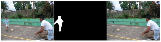
Figure 7. Original image, the applied mask, and the Criminisi result.
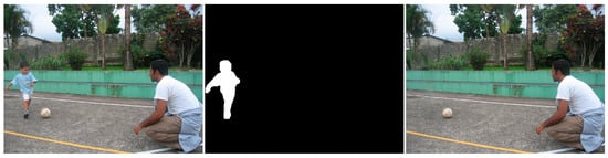
Figure 8. Original image, the applied mask, and the Huang result.
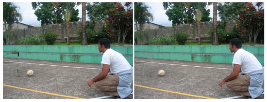
Figure 9. Reconstructed image by Criminisi vs. that by Huang.
The first artifact analyzed is incorrect color or texture continuation. It arises when the inpainting algorithm fails to accurately reproduce the color or texture of the surrounding area when filling in the missing region or when the inpainting algorithm copies patches that do not fit well with the surrounding structure of the image. This can lead to unnatural and unrealistic transitions between the inpainted region and the surrounding pixels. One of the primary reasons for incorrect color or texture continuation is the limited information available to the inpainting algorithm. When copying patches from the surrounding area, the algorithm only considers the colors and textures within the patch itself. This can be insufficient to accurately determine the continuation of color or texture across the missing region, especially in areas with complex or subtle variations. Another factor contributing to this artifact is the randomness involved in the patch selection process. When choosing patches from the surrounding area, the algorithm does not necessarily select patches that are most similar in color or texture to the missing region. This can lead to discrepancies in the color or texture representation, making the transition between the inpainted region and the surrounding pixels appear unnatural. This type of artifact is presented in the zoomed image in Figure 10 after applying the Criminisi method:
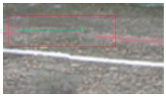
Figure 10. Zoomed area with incorrect color continuation.
Another type of common artifact is aliasing, also known as the staircase effect or jaggy edges. It is a common artifact that can occur in patch-based image inpainting. It arises due to the limitations of the algorithm in accurately replicating the delicate details of the original image, particularly along high-frequency edges. When the inpainting algorithm copies patches from the surrounding area to fill in the missing region, it often struggles to maintain the sharp transitions and gradients that define edges. This is because the algorithm is averaging the pixel values within the patch, which can result in a smoothing effect that blurs the edges. Therefore, the reconstructed edges appear jagged or pixelated, resembling a staircase-like pattern. This is particularly evident in regions with high contrast and sharp transitions, such as the outlines of objects or the edges of textures. The aliasing effect is caused by the sampling process employed by the inpainting algorithm. When copying patches from the surrounding area, the algorithm relies on a fixed sampling rate, which means that it only considers a limited number of pixels from each patch. This limited sampling cannot fully capture the fine details of the image, especially along the edges where the pixel values vary rapidly. As a result, the algorithm struggles to accurately reproduce these details when filling in the missing region, leading to the staircase effect. This is visible in Figure 11.
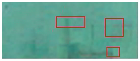
Figure 11. Zoomed area of the Criminisi result in which jagged areas can be seen.
Blurring is another common artifact that can occur in patch-based image inpainting, particularly when dealing with intricate textures or high-contrast edges. It arises due to the averaging process employed by the inpainting algorithm when copying patches from the surrounding area. When filling in the missing region, the algorithm averages the pixel values within the copied patch, effectively smoothing out the fine details and reducing the sharpness of edges. This blurring effect becomes more pronounced in regions with complex textures or sharp transitions, as the averaging process fails to capture the intricate patterns and gradients. The blurring artifact primarily stems from the limited receptive field of the inpainting algorithm. When copying a patch, the algorithm only considers the pixels within that patch, essentially operating within a narrow area. This restricted view prevents the algorithm from fully comprehending the wider context of the image, including the intricate details and sharp edges that define textures and objects. For example, by applying this method [30], in Figure 12, the zoomed area is visualized.
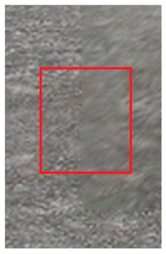
Figure 12. Zoomed area of the Huang result in which blurring is presented.
The blurring effect is more pronounced, particularly when the region to be inpainted has a high level of texture. For example, in Figure 15, the Huang method is applied.
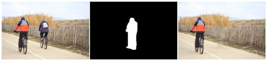
Figure 13. Original image, the applied mask, and Huang result on highly texturized area.
Since the region being inpainted is textured, the outcome is highly blurred, and in the below zoomed region, this can be observed in Figure 16.
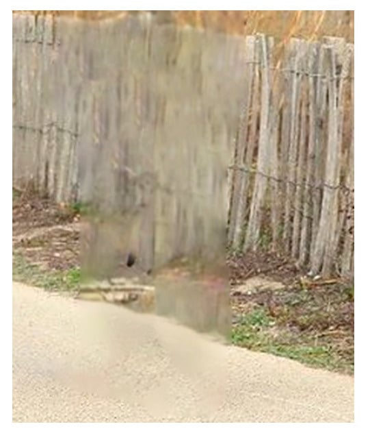
Figure 13. Zoomed area in which blurring artifacts are present.
By analyzing the artifacts these methods introduce, the methods can be categorized into two groups: methods that simply “copy-paste” unconnected/unrelated regions (patches) into the missing area and methods that do some enhancement/adaptation of the patch values. The first category is straightforward to determine via a forensic algorithm: it relies solely on the fact that a given region (usually several times greater than the patch used for inpainting) is comprised of patches that have “references” in other areas. The main problems here are how to determine the correct patch size to be able to determine “copies” and speed and last but not least, how to correctly eliminate false positives (especially when the patch size is smaller, and the window step is small as well). The second category of inpainting patch-based methods that do not simply copy the source patch to the destination is a little harder to detect. The above algorithm, where similar patches are searched for, can no longer be applied, and thus, some new heuristic must be introduced and evaluation on how much resemblance the patches have should be revisited. If the patch similarity mechanism is updated, the problem of false positives increases exponentially and on images with large smooth textures, a lot of false positives might be reported. Still, there are some clues that can be used as starting points, like incorrect texture inconsistencies or blurring.
4. Machine Learning-Based Methods
Deep learning methods have significantly improved the accuracy and effectiveness of image inpainting. Given its exceptional outcomes, numerous researchers are motivated to revise, employ, or even adopt novel methodologies. Image inpainting includes deep learning techniques, specifically convolutional neural networks (CNNs). The objective is to utilize a training set of images to instruct the convolutional neural networks (CNNs) in the task of filling or completing the sections or regions that are absent in the images. The initial approach to address image inpainting is training a specialized model to fill in a missing area at a particular position inside an image. Other architecture like encoder-decoder, combined with generative adversarial networks and utilizing deep learning techniques, have outperformed previous methods. Based on this observation, some authors have tried to categorize machine learning inpainting methods into CNN- and GAN-based methods [31]. In [32], a comprehensive overview of the latest prominent image inpainting techniques is provided based on deep learning in two groups: single-stage methods and progressive methods. Other researchers categorized deep learning-based methods into three groups: those utilizing autoencoders, those employing generative models, and those focusing on network structure optimization. Prior studies failed to account for methods using diffusion-based models or transformers. For a detailed review on machine learning-based techniques, authors in [32][33] offer particularly good overviews of the current state-of-the-art methods. Recent years have also shown promising results in models based on diffusion or more complex models based on transformers. Grouping inpainting methods based on model structure is a practical and insightful approach for several reasons, especially in inpainting detection, as listed below:
- -
-
Underlying Mechanism and Approach—Different model structures use fundamentally different mechanisms and approaches to inpainting. For example, autoencoders leverage an encode-decode framework, GANs rely on adversarial training between a generator and discriminator, diffusion models use a probabilistic approach to gradually construct an image, and transformers process global dependencies in data. Understanding these core mechanisms helps in selecting the right model for a specific type of inpainting task.
- -
-
Strengths and Limitations—Each model structure has its unique strengths and limitations. Autoencoders are efficient but may struggle with high-frequency details, GANs can generate high-quality images but often face training stability issues, diffusion models excel in producing coherent and detailed images but are computationally intensive, and transformers are excellent at capturing long-range dependencies but may face challenges with local coherence. Grouping by structure allows for a clear comparison of these strengths and limitations.
- -
-
Artifacts and Quality of Output—Probably, from a detection point of view, the most important aspect is that similar artifacts are introduced by the same type of model. Different structures tend to produce different kinds of artifacts in the inpainted images, as discussed earlier. By grouping methods based on structure, it is easier to anticipate the types of artifacts that might arise and choose a method that minimizes undesired effects for a given application.
Therefore, the methods for inpainting are categorized as follows:
- -
-
GAN-based methods;
- -
-
Diffusion models;
- -
-
Transformers.
In the below sections, only relevant methods from each group are analyzed, along with relevant artifacts from each group. In the area of machine learning, the most referenced method, which is attributed to Deepak Pathak’s paper [34], suggests the use of a system composed of an encoder and a decoder. The encoder focuses on retaining data information (extracting it), and the decoder’s responsibility is to generate features based on the encoder’s learned data. Starting with this approach, several methods have initially been suggested, like FCN that has two neural networks with skip connections between them. An improved version of this FCN version is U-Net architecture, which resembles FCN but uses summation as a skip connection mechanism and employs concatenation. The advantage of using concatenation is that it can retain more detailed data. One of the existing problems with inpainting is how to generate the missing area in a highly texturized area. To address this challenge, some authors have proposed different mechanisms to exploit both global and local texture information. Another point of variation between inpainting methods is the convolutions used. The focus is more on the convolution applied at the decoder level (deconvolution or as some authors call it, transposed convolutional layer) because it is the one responsible for introducing several types of artifacts. From the analysis, the most used convolutions are simple (or standard) convolution—which is good for reconstruction, especially for rectangular-based shapes—and gated convolution, the main idea of which is to be able to fill in irregular holes by using a mask that is updated after each convolution [25][32][33].
Recent research with relevant satisfactory results are [35][36][37]. The methods used rely on Fourier convolutions and perceptual loss. Their results are impressive in the CelebA [38] and places [39] datasets. An improvement on the Lama model was presented by the authors in [40] on the learned perceptual image patch similarity (LPIPS) metric. Their method starts with a noisy image and applies denoising, filling in the missing data based on the known area. In [41], the authors suggested another approach in that they apply an already established classic method of inpainting from OpenCV (Telea and NS methods) and use a CNN model to learn the reconstruction of these features. As a backbone, they use a VGG16 model and as features, the authors used three distinct traits: image size, RGB information, and brightness levels. The results are straightforward when the area to be inpainted is uniform (e.g., the middle of the sky), but when the region to be generated is at the border of several highly texturized areas, the methods do not yield proper results. Recently in [42], they suggested that the task of inpainting should be divided into two separate stages. In the first stage, they used two separate DRGAN modules—one to generate the content of the inpainted area and one to generate the edges of the missing area; they generated a label image where 1 is the edge, and 0 represents the background. This information is crucial in the second stage of the algorithm, where the authors used a fine-grained network to generate more coarse pixel information based on the label edges and the already generated data. Again, they used a DRGAN architecture, a deep residual generative adversarial network, for this part of the method. Analyzing the results and the comparison with some state-of-the-art methods, the proposed method can reconstruct highly texturized areas but has some limitations in what the authors call “overly complex” regions. Authors in [43] diverged from the mainstream usage of transformers and incorporated a discrete wavelet transformer along the convolutional layers. Still, for up sampling, the authors used the standard transpose convolution, which generates checkboard artifacts. Another approach with particularly good results is [44], in which the authors combined autoencoders and transformers on a Resnet architecture. The idea behind using transformers is that they can better represent details and thus be able to reconstruct the missing area, but the authors still used the same type of architecture (Resnet), which employs the same type of up sampler. In [45], the authors present a new class of diffusion models called latent diffusion models (LDMs) that achieve state-of-the-art performance for image inpainting and other tasks, including unconditional image generation, semantic scene synthesis, and super resolution. LDMs are based on the idea of decomposing the image formation process into a sequential application of denoising autoencoders. This allows LDMs to be trained with a more efficient training process, and it also allows for more flexible control over the image generation process. In the paper, the authors compare LDMs to pixel-based diffusion models (PDMs), which are the most common type of diffusion model. They found that LDMs are significantly more efficient than PDMs, and they also produce higher quality results. The authors conclude that LDMs are a promising new approach to image synthesis, and they believe that they have the potential to revolutionize the way that images are generated and used. Among the limitations, the most common ones are mode collapse; in some cases, LDMs may exhibit mode collapse where they consistently produce similar-looking inpainted images, even when presented with different input masks and texture artifacts. LDMs can sometimes introduce texture artifacts, such as blurry or unnatural patterns, in the inpainted regions. These artifacts arise from the model’s tendency to smooth out sharp edges and fine details in the input image.
Diffusion-, GAN-, and transformer-based image inpainting methods each have their own strengths and weaknesses in terms of artifact production. Here is a summary of the common artifacts associated with each method.
- -
-
Diffusion-based inpainting
- ▪
-
Texture artifacts: Diffusion-based models can introduce blurry or unnatural textures in the inpainted regions, especially when dealing with complex textures or high-resolution images. This is because diffusion models gradually reduce noise from the input image, potentially over smoothing fine details.
- ▪
-
Color inconsistencies: Color inconsistencies can also occur with diffusion-based inpainting, leading to discrepancies in color saturation or hue between the inpainted areas and the surrounding pixels. This can make the inpainted image appear unnatural or unrealistic.
- ▪
-
Ghosting artifacts: Diffusion-based models may introduce ghosting artifacts around the edges of the inpainted areas, making them look detached from the surrounding image. This can be caused by the model’s tendency to overemphasize the edges of the missing regions.
- -
-
GAN-based inpainting
- ▪
-
Mode collapse: GAN-based models can sometimes suffer from mode collapse, where they consistently produce similar-looking inpainted images even when presented with different input masks. This can limit the diversity and creativity of the generated inpainting results.
- ▪
-
Fake artifacts: GAN-based models may introduce artifacts that appear fake or artificial, such as checkerboard patterns, blurry textures, or unnatural patterns. This can happen when the model struggles to capture the fine details and subtle textures of the original image.
- ▪
-
Color artifacts: Color artifacts can also occur with GAN-based inpainting, especially in early generations or when the model is not trained properly. This can make the inpainted image appear unnatural or unrealistic.
- -
-
Transformer-based inpainting
- ▪
-
Pixelation: Transformer-based models can sometimes produce pixelated artifacts, especially when inputting low-resolution images or when generating images with sharp edges or high contrast. This is because the attention mechanism used in transformers may focus on a small number of pixels, leading to a loss of detail in the final output.
- ▪
-
Checkerboard patterns: Checkerboard patterns can also be introduced by transformers, especially when generating images with sharp edges or high contrast. This is because the attention mechanism may not be able to smoothly transition between different regions of the image, leading to a checkerboard-like appearance.
- ▪
-
Color banding: Transformers can also introduce color banding artifacts, which appear as horizontal or vertical stripes of color. This is typically caused by the model’s inability to accurately represent smooth gradients of color.
In general, diffusion-based inpainting is known for its ability to produce smooth and realistic results, but it may introduce texture artifacts and ghosting artifacts. GAN-based inpainting can generate diverse and realistic inpainting results, but it is more prone to mode collapse and fake artifacts. Transformer-based inpainting excels at high-resolution inpainting but may suffer from pixelation and checkerboard artifacts.
Machine learning-based inpainting methods, particularly those using convolutional neural networks (CNNs) like Lama (large mask inpainting), have made significant advances in image restoration and object removal. However, these methods still introduce specific artifacts, which can vary depending on the algorithm’s design, training data, and the complexity of the inpainting task. The most common artifacts introduced by these methods include blurring, inconsistent textures, color discrepancies or repetition, and pattern duplication. Blurring, loss of detail, and over smoothing: machine learning algorithms, especially earlier or simpler models, can struggle to reproduce fine details. This often results in inpainted areas that are blurrier or less detailed compared to the original image’s parts. Sometimes, these models may also smooth out the natural texture and structure of the image, making the inpainted region appear artificial, like in Figure 14:
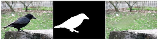
Figure 14. Original image, the applied mask, and Lama result with blurring and smoothing effect.
Inconsistent textures arise when the inpainting process duplicates patches of pixels from the surrounding area that do not correspond to the texture of the area that is missing. This might result in an artificial appearance, giving the impression that the area that is missing has been replaced with a dissimilar substance. For instance, in the Figure 15 example, if the inpainting algorithm removes the knife, the outcome appears artificial due to the mismatch in textures between the removed area and the rest of the image.
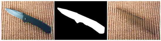
Figure 15. Original image, the applied mask, and Lama result with inconsistent textures and coloring.
In the above image, color disparities can be seen as well. These artifacts arise when the inpainting algorithm employs hues that do not correspond to the hues of the adjacent region. This can result in an artificial appearance, giving the impression that the area that is missing has been replaced with a distinct object.
Edge artifacts manifest when the inpainting method is unable to precisely rebuild the boundaries of the absent area. These imperfections can result in the appearance of uneven or blocky edges that can be seen in the restored image. For instance, if an inpainting method is employed to eliminate an object from a forest image (see Figure 16), the edges of the object would remain discernible in the inpainted image due to the system’s inability to precisely rebuild the intricate forms of the leaves and branches.
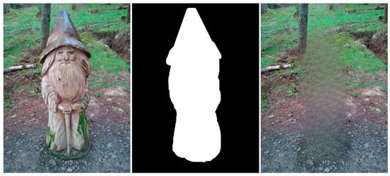
Figure 16. Original image, the applied mask, and Lama result with edge artifacts and structural and geometric errors.
Structural and geometric errors arise when the inpainting process fails to accurately restore an image’s general structure and geometry. These actions may result in the formation of discontinuities or boundaries between the restored area and the adjacent pixels as well as the potential alteration of the image’s general morphology, as can be seen in the above example.
Although less common than in patch-based methods, some ML algorithms can produce repetitive patterns, especially when dealing with large inpainting areas. For example, sometimes the Lama method generates patterns like the ones presented in Figure 17.
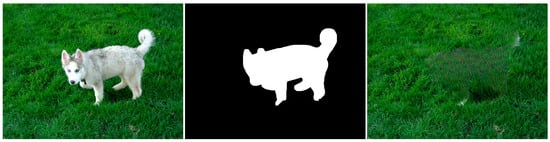
Figure 17. Original image, the applied mask, and Lama result with repetitive patterns.
From a detection point of view, these methods are becoming more challenging due to their ability to propagate patches that are indistinguishable from the rest of the image. Also, due to their nature to complete large areas, they can reconstruct entire image characteristics. Various methods have been proposed as attack vectors, but they are focusing on the artifacts introduced by the various up sampling steps. One can focus on artifacts like the ones described above, but they are harder to implement because there is the need for complete image segmentation, and thus after having understood the image, one can easily spot the inconsistencies.
This entry is adapted from the peer-reviewed paper 10.3390/jimaging10020042
References
- Bertalmio, M.; Sapiro, G.; Caselles, V.; Ballester, C. Image inpainting. In Proceedings of the 27th Annual Conference on Computer Graphics and Interactive Techniques—SIGGRAPH ’00, New Orleans, LA, USA, 23–28 July 2000; ACM Press: New York, NY, USA, 2000; pp. 417–424.
- Bertalmío, M.; Bertozzi, A.L.; Sapiro, G. Navier-Stokes, fluid dynamics, and image and video inpainting. In Proceedings of the IEEE Computer Society Conference on Computer Vision and Pattern Recognition, Kauai, HI, USA, 8–14 December 2001; Volume 1.
- Bertalmío, M. Contrast invariant inpainting with a 3RD order, optimal PDE. In Proceedings of the IEEE International Conference on Image Processing 2005, Genova, Italy, 14 September 2005; Volume 2, pp. 775–778.
- Chan, T.F.; Shen, J. Nontexture Inpainting by Curvature-Driven Diffusions. J. Vis. Commun. Image Represent. 2001, 12, 436–449.
- Chan, T.F.; Kang, S.H.; Shen, J. Euler’s Elastica and Curvature-Based Inpainting. SIAM J. Appl. Math. 2006, 63, 564–592.
- Schönlieb, C.B.; Bertozzi, A. Unconditionally stable schemes for higher order inpainting. Commun. Math. Sci. 2011, 9, 413–457.
- Jidesh, P.; George, S. Gauss curvature-driven image inpainting for image reconstruction. J. Chin. Inst. Eng. 2014, 37, 122–133.
- Sridevi, G.; Kumar, S.S. p-Laplace Variational Image Inpainting Model Using Riesz Fractional Differential Filter. Int. J. Electr. Comput. Eng. 2017, 7, 850–857.
- Sridevi, G.; Kumar, S.S. Image Inpainting and Enhancement using Fractional Order Variational Model. Def. Sci. J. 2017, 67, 308–315.
- Sridevi, G.; Kumar, S.S. Image Inpainting Based on Fractional-Order Nonlinear Diffusion for Image Reconstruction. Circuits Syst. Signal Process. 2019, 38, 3802–3817.
- Gamini, S.; Gudla, V.V.; Bindu, C.H. Fractional-order Diffusion based Image Denoising Mode. Int. J. Electr. Electron. Res. 2022, 10, 837–842.
- Papafitsoros, K.; Schoenlieb, C.B.; Sengul, B. Combined First and Second Order Total Variation Inpainting using Split Bregman. Image Process. Line 2013, 3, 112–136.
- Efros, A.A.; Leung, T.K. Texture Synthesis by Non-parametric Sampling. In Proceedings of the Seventh IEEE International Conference on Computer Vision, Kerkyra, Greece, 20–27 September 1999.
- Criminisi, A.; Pérez, P.; Toyama, K. Region filling and object removal by exemplar-based image inpainting. IEEE Trans. Image Process. 2004, 13, 1200–1212.
- Ružić, T.; Pižurica, A. Context-aware patch-based image inpainting using Markov random field modeling. IEEE Trans. Image Process. 2015, 24, 444–456.
- Jin, K.H.; Ye, J.C. Annihilating Filter-Based Low-Rank Hankel Matrix Approach for Image Inpainting. IEEE Trans. Image Process. 2015, 24, 3498–3511.
- Kawai, N.; Sato, T.; Yokoya, N. Diminished Reality Based on Image Inpainting Considering Background Geometry. IEEE Trans. Vis. Comput. Graph. 2016, 22, 1236–1247.
- Guo, Q.; Gao, S.; Zhang, X.; Yin, Y.; Zhang, C. Patch-Based Image Inpainting via Two-Stage Low Rank Approximation. IEEE Trans. Vis. Comput. Graph. 2018, 24, 2023–2036.
- Lu, H.; Liu, Q.; Zhang, M.; Wang, Y.; Deng, X. Gradient-based low rank method and its application in image inpainting. Multimed. Tools Appl. 2018, 77, 5969–5993.
- Shen, L.; Xu, Y.; Zeng, X. Wavelet inpainting with the ℓ0 sparse regularization. Appl. Comput. Harmon. Anal. 2016, 41, 26–53.
- Waller, B.M.; Nixon, M.S.; Carter, J.N. Image reconstruction from local binary patterns. In Proceedings of the 2013 International Conference on Signal-Image Technology & Internet-Based Systems, Kyoto, Japan, 2–5 December 2013; pp. 118–123.
- Li, H.A.; Hu, L.; Liu, J.; Zhang, J.; Ma, T. A review of advances in image inpainting research. Imaging Sci. J. 2023.
- Rasaily, D.; Dutta, M. Comparative theory on image inpainting: A descriptive review. In Proceedings of the 2017 International Conference on Energy, Communication, Data Analytics and Soft Computing (ICECDS), Chennai, India, 1–2 August 2017; pp. 2925–2930.
- Shen, B.; Hu, W.; Zhang, Y.; Zhang, Y.J. Image inpainting via sparse representation. In Proceedings of the 2009 IEEE International Conference on Acoustics, Speech and Signal Processing, Taipei, China, 19–24 April 2009; pp. 697–700.
- Xu, Z.; Sun, J. Image inpainting by patch propagation using patch sparsity. IEEE Trans. Image Process. 2010, 19, 1153–1165.
- Tiefenbacher, P.; Sirch, M.; Babaee, M.; Rigoll, G. Wavelet contrast-based image inpainting with sparsity-driven initialization. In Proceedings of the 2016 IEEE International Conference on Image Processing (ICIP), Phoenix, AZ, USA, 25–28 September 2016; pp. 3528–3532.
- Bugeau, A.; Bertalmío, M.; Caselles, V.; Sapiro, G. A comprehensive framework for image inpainting. IEEE Trans. Image Process. 2010, 19, 2634–2645.
- Aujol, J.F.; Ladjal, S.; Masnou, S. Exemplar-Based Inpainting from a Variational Point of View. SIAM J. Math. Anal. 2010, 42, 1246–1285.
- Casaca, W.; Boaventura, M.; De Almeida, M.P.; Nonato, L.G. Combining anisotropic diffusion, transport equation and texture synthesis for inpainting textured images. Pattern Recognit. Lett. 2014, 36, 36–45.
- Huang, J.B.; Kang, S.B.; Ahuja, N.; Kopf, J. Image completion using planar structure guidance. ACM Trans. Graph. (TOG) 2014, 33, 1–10.
- Elharrouss, O.; Almaadeed, N.; Al-Maadeed, S.; Akbari, Y. Image inpainting: A review. Neural Process. Lett. 2019, 51, 2007–2028.
- Qin, Z.; Zeng, Q.; Zong, Y.; Xu, F. Image inpainting based on deep learning: A review. Displays 2021, 69, 102028.
- Jam, J.; Kendrick, C.; Walker, K.; Drouard, V.; Hsu, J.G.S.; Yap, M.H. A comprehensive review of past and present image inpainting methods. Comput. Vis. Image Underst. 2021, 203, 103147.
- Pathak, D.; Krahenbuhl, P.; Donahue, J.; Darrell, T.; Efros, A.A. Context Encoders: Feature Learning by Inpainting. In Proceedings of the IEEE Conference on Computer Vision and Pattern Recognition (CVPR), Las Vegas, NV, USA, 27–30 June 2016; pp. 2536–2544.
- Suvorov, R.; Logacheva, E.; Mashikhin, A.; Remizova, A.; Ashukha, A.; Silvestrov, A.; Kong, N.; Goka, H.; Park, K.; Lempitsky, V. Resolution-robust Large Mask Inpainting with Fourier Convolutions. In Proceedings of the IEEE/CVF Winter Conference on Applications of Computer Vision (WACV), Waikoloa, HI, USA, 3–8 January 2022; pp. 3172–3182.
- Lu, Z.; Jiang, J.; Huang, J.; Wu, G.; Liu, X. GLaMa: Joint Spatial and Frequency Loss for General Image Inpainting. In Proceedings of the IEEE/CVF Conference on Computer Vision and Pattern Recognition (CVPR) Workshops, New Orleans, LA, USA, 18–24 June 2022; pp. 1300–1309.
- Shamsolmoali, P.; Zareapoor, M.; Granger, E. Image Completion Via Dual-Path Cooperative Filtering. In Proceedings of the ICASSP 2023—2023 IEEE International Conference on Acoustics, Speech and Signal Processing (ICASSP), Rhodes Island, Greece, 4–10 June 2023; pp. 1–5.
- Liu, Z.; Luo, P.; Wang, X.; Tang, X. Deep Learning Face Attributes in the Wild. In Proceedings of the IEEE International Conference on Computer Vision (ICCV), Santiago, Chile, 7–13 December 2015.
- Zhou, B.; Lapedriza, A.; Khosla, A.; Oliva, A.; Torralba, A. Places: A 10 Million Image Database for Scene Recognition. IEEE Trans. Pattern Anal. Mach. Intell. 2018, 40, 1452–1464.
- Lugmayr, A.; Danelljan, M.; Romero, A.; Yu, F.; Timofte, R.; Van Gool, L. RePaint: Inpainting using Denoising Diffusion Probabilistic Models. In Proceedings of the IEEE/CVF Conference on Computer Vision and Pattern Recognition (CVPR), New Orleans, LA, USA, 18–24 June 2022; pp. 11451–11461.
- Cho, R.K.; Sood, K.; Channapragada, C.S.C. Image Repair and Restoration Using Deep Learning. In Proceedings of the 2022 4th International Conference on Artificial Intelligence and Speech Technology (AIST), Delhi, India, 9–10 December 2022.
- Chen, Y.; Xia, R.; Yang, K.; Zou, K. DGCA: High resolution image inpainting via DR-GAN and contextual attention. Multimed. Tools Appl. 2023, 82, 47751–47771.
- Jeevan, P.; Kumar, D.S.; Sethi, A. WavePaint: Resource-Efficient Token-Mixer for Self-Supervised Inpainting. July 2023. Available online: https://arxiv.org/abs/2307.00407v1 (accessed on 10 September 2023).
- Esser, P.; Rombach, R.; Ommer, B. Taming transformers for high-resolution image synthesis. In Proceedings of the IEEE/CVF Conference on Computer Vision and Pattern Recognition (CVPR), Nashville, TN, USA, 20–25 June 2021; pp. 12868–12878.
- Rombach, R.; Blattmann, A.; Lorenz, D.; Esser, P.; Ommer, B. High-Resolution Image Synthesis with Latent Diffusion Models. In Proceedings of the IEEE/CVF Conference on Computer Vision and Pattern Recognition (CVPR), New Orleans, LA, USA, 18–24 June 2022; pp. 10674–10685.
This entry is offline, you can click here to edit this entry!