The electrical grid is predominantly characterized by synchronous generators (SGs). These generators provide a consistent voltage and frequency, facilitating the synchronization of VSIs and their connection at the point of common coupling (PCC) for injecting power into the main grid. These inverters operate as current sources and are known as grid-following inverters. The imperfections of grid-following inverters arise when the grid is absent, as this concept fails to produce instantaneous voltage and frequency set points. Therefore, this operating mode has been significantly modified, from following the grid to leading it. This concept is known as grid-forming (GFM) inverters, which can independently set up and keep the voltage and frequency within their nominal ranges without the need for the main grid.
1. Introduction
The amount of renewable energy generation systems that are connected to the grid is continuously increasing. Consequently, the presence of power electronics devices in power systems has also increased. At present, the electrical grid is predominantly characterized by synchronous generators (SGs). These generators provide a consistent voltage and frequency, facilitating the synchronization of VSIs and their connection at the point of common coupling (PCC) for injecting power into the main grid. These inverters operate as current sources and are known as grid-following inverters. The imperfections of grid-following inverters arise when the grid is absent, as this concept fails to produce instantaneous voltage and frequency set points. Therefore, this operating mode has been significantly modified, from following the grid to leading it. This concept is known as grid-forming (GFM) inverters, which can independently set up and keep the voltage and frequency within their nominal ranges without the need for the main grid [
1]. The block diagram of both concepts is depicted in
Figure 1.
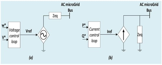
Figure 1. Power converter classification: (a) grid-forming and (b) grid-following inverters.
GFM inverter control consists of a voltage control path that regulates the output voltage to a specified voltage reference and a phase-angle reference path that integrates a predetermined frequency to obtain the phase-angle reference. These references (voltage and frequency) are commonly achieved through decentralized control such as droop control [
2,
3], virtual synchronous machines [
4], virtual SG [
5], synchronverter [
6], power synchronization control [
7], generalized virtual synchronous control [
8], and virtual oscillator control [
9]. Presently, the biggest challenges for decentralized control schemes are the seamless reconnection and black-start of GFM inverters [
10].
The decentralized control for GFM inverters is generally composed of inner control loops for current and voltage, a virtual impedance loop, and a controller employing a droop mechanism [
11]. The primary control objectives for GFM inverters involve stabilizing amplitudes and ensuring power sharing among them. The stabilization of frequency and voltage is typically accomplished through current and voltage control loops, while the droop control mechanism facilitates power sharing [
12].
2. GFM Inverter Control Methods
The decentralized control design is very important for the GFM inverter’s performance. Various control approaches for GFM inverters are examined and compared with the GFM characteristics exhibited by synchronous machines in [
13]. A hybrid grid-forming/following controller was proposed in [
14]. Voltage synchronization is achieved by incorporating a phase-locked loop (PLL), and load sharing is facilitated through the utilization of a power-frequency droop. A droop-based GFM adaptive virtual resistance control was suggested in [
15] for postfault oscillation mitigation in GFM inverters. In [
16], authors investigated the use of impedance-based analysis to define, assess, and enhance the performance of GFM inverter controllers in various ways. In [
17], a multivariable controller was proposed with the aim of decoupling P and Q loops in GFM inverters using droop control and other methods. A decentralized control approach for multiparallel GFM-distributed generators on island MG was developed in [
18]. It offers the advantage of decoupling the frequency from load conditions. The authors in [
19] explored GFM inverter modeling and control methodology, focusing on droop control. Embedding voltage and current loops within a single controller is a strategy that can significantly enhance the dynamic performance of the GFM system, as discussed in [
20]. In MG’s with mismatched inductive/resistive feeder impedance, the virtual impedance loop, acting as an optional loop, plays a role in improving the power quality and power-sharing accuracy of GFM systems [
21]. Drawbacks such as steady-state error and deviations in frequency and voltage amplitude are associated with the GFM droop control mechanism [
22]. Consequently, a secondary control is introduced to mitigate these deviations [
23]. Despite the deviations introduced by the total demand for active and reactive power from the loads, the GFM inverter system effectively restores both frequency and amplitude [
24]. Additionally, a threshold-based method for frequency and voltage restoration in islanded MGs fed by droop-controlled GFM is proposed in [
25]. It aims to restore the system when pulse load and plug-in events occur. A relevant solution for enhancing the efficiency and power quality of GFM inverters can be found in compact inverter structures, as demonstrated in [
26].
The primary focus of the above studies is on the dynamics of GFM microgrids. This focus intensifies specifically after a disturbance in the system when GFM inverters are operated in parallel. Less attention has been given to the synchronization and reconnection of GFM inverters in MG or the synchronization of GFM microgrids to the main grid. The main difficulty is the lack of information about voltage, frequency, and phase angle at the PCC. Hence, the synchronization with other sources and proportional contribution to power-sharing in the (V-f) mode becomes challenging tasks for the incoming inverter. Likewise, when transitioning from islanded operation to grid-connected mode, the synchronization of the MG with the main grid is a necessary step. Thus, a synchronization control algorithm is necessary. A seamless connection to the MG/grid is essential for both GFM and grid-following inverters. A synchronization method for inverters in GFM, known as the controller-sync, is proposed in [
27]. In this approach, the inverter initially aligns with the MG frequency without contributing to power sharing. Subsequently, the controller transitions to power-sharing mode. A communication-based method to synchronize the GFM microgrid to the utility grid is proposed in [
28]. This approach is based on exchanging data between two proposed devices: synchronization data sender and a synchronization data controller.
In summary, the current state of research reveals certain gaps:
-
The comprehensive applicability of droop-based control in GFM inverters remains inadequately addressed.
-
The analysis of the decentralized control’s performance is lacking, particularly in the context of off-grid systems and varying PQ load demands.
Furthermore, when it comes to synchronization techniques, several gaps exist:
-
While many techniques address the connection of inverters to the utility grid, there is a lack of exploration regarding the (re)connection of an inverter to an islanded MG.
-
The majority of techniques are designed for inverters operating in (P-Q) control mode, leaving a gap in the understanding of inverters in (V-f) control mode post-(re)connection.
-
Certain methods require communication infrastructure, leading to cost implications for the seamless plug-and-play operation of inverters and exposing them to potential cyber-attacks.
This entry is adapted from the peer-reviewed paper 10.3390/en17010059