Your browser does not fully support modern features. Please upgrade for a smoother experience.
Please note this is an old version of this entry, which may differ significantly from the current revision.
Subjects:
Automation & Control Systems
Contactless identification cards based on RFID technology are currently an integral part of many human activities in industry, transport, trade, etc. The most used cards are contactless cards operating at 13.56 MHz, according to the ISO/IEC 14443 standard, and using some version of the NXP Mifare chip.
- RFID
- Mifare
- current pulse
- voltage limiter
- approximation
1. Introduction
Contactless identification cards based on RFID technology [1] are currently an integral part of many human activities in industry, transport, trade, etc. The most used cards are contactless cards operating at 13.56 MHz, according to the ISO/IEC 14443 standard [2], and using some version of the NXP Mifare chip. Great emphasis is placed on the information security of the data stored in the chips of these cards. The immunity of these cards (or other forms of RFID transponders) to external electromagnetic fields which, in unfavourable cases, can destroy the identification chip by inducing a current pulse exceeding the safe value given by the chip manufacturer, is considered less often.
In practice, there are several cases in which RFID transponders can be destroyed by a current pulse induced from an adjacent linear conductor. Figure 1 documents the use of RFID for marking underground cables and pipes. If these are metallic, they can conduct, e.g., part of the lightning current, endangering the transponder. The authors already have their own experience with such cases of transponder destruction. A similar situation can occur when embedding an RFID transponder in reinforced concrete in a bridge structure [3]. An example of an RFID transponder application (in this case, the UHF frequency band is used) in a railway vehicle chassis is given in [4], an environment with high traction currents. Other examples of the use of RFID technology in adverse environments with high currents are provided in [5] (RFID sensors for energy transmission lines), [6,7] (inductive power transfer for e-bikes equipped with RFID), and [8] (underground pipe monitoring). In [9], the design of a UHF RFID transponder for application in a strong electromagnetic field is described. Finally, for information security, the possibility of the targeted destruction of RFID cards with sensitive information (e.g., personal certificates) by a pulse in an external inductively coupled conductor (in this case, maybe a coil) is also interesting.
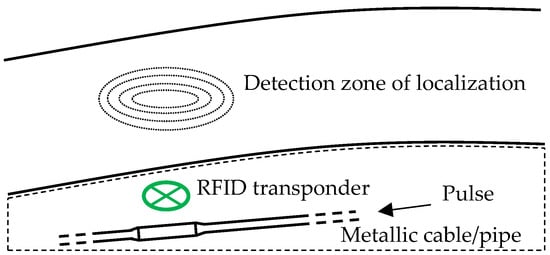
Figure 1. RFID transponder used for marking and locating the underground cables and pipes.
Each chip intended for incorporation into an RFID transponder, in addition to logic and memory elements, contains a voltage limiter that limits the maximum value of (alternating) voltage on the chip to approximately 4–8 V. The current–voltage characteristic of such a limiter looks like an anti-serially connected pair of Zener diodes characteristics, which causes significant nonlinear distortion of signals induced into the RFID transponder from reading devices. In the case of overcurrent induction (several tens of mA, [10]), the RFID transponder may be destroyed.
2. Evaluation of Contactless Identification Card Immunity against a Current Pulse in an Adjacent Conductor
The identification chips used in RFID transponders are principally nonlinear semiconductor components, usually manufactured using CMOS technology. The analysis and design of such chips are explained, e.g., in [13]. The nonlinear properties of identification chips for the UHF frequency band are described in [14,15,16]. The nonlinearity of HF RFID chips was documented in [17,18] by measuring the impedance of chips depending on the supply voltage within the allowed range according to the datasheets of the used chips. A powering circuit (rectifier and voltage regulator) for ISO/IEC 14443-compliant RFID chips based on CMOS technology was designed in [19]. However, this paper focuses on something other than the voltage limiter, which is mentioned only marginally. A detailed design of a voltage limiter for an RFID chip, specifically for the UHF frequency band, is provided in [20]. This design uses NMOS and PMOS transistors as a controlled load directly connected to the antenna terminals to limit the RF power in the chip. The analogue front-end for the 13.56 MHz transponder, including a powering circuit based on lateral MOS transistors, is described in [21,22]. The influence of a parallel-connected energy harvester on RFID transponder performance is modelled and measured in [23]. Other scientific works concerning power supply circuits of RFID chips are presented in [19,24,25,26,27,28,29].
The simplified mathematical model of the RFID chip used to calculate the current induced in the transponder assumes the approximation of the nonlinear current–voltage characteristic of the identification chip using suitable equations based on the mathematical description of the Zener diode. In general, sources [30,31] have dealt with the issue of semiconductor physics, while a more detailed analysis of models of semiconductor junctions applicable to Zener diodes can be found in [32,33,34].
Technical praxis is based on the regulations in the technical standard to evaluate the impact of overcurrent pulses caused by lightning [35]. This standard defines the time courses of voltage and current pulses, the simplified mathematical description of which can be found in the [36]. Electromagnetic compatibility tests of the proximity and vicinity identification cards and readers, e.g., intensity of magnetic field, sensitivity to electrostatic discharge, interferences etc., are described in the standards ISO/IEC 10373-6 [37] (for proximity devices, e.g., cards based on the NXP Mifare chip family) and ISO/IEC 10373-7 [38] (for vicinity devices, e.g., cards based on the NXP I-code chip family). These tests define the working conditions of the cards and readers that they must pass without damage.
RFID cards damaged during tests and measurements were measured using contactless means using a vector network analyser to calculate their state after the damage. For calculations, mutual relations between measured scattering parameters and the theoretical transfer function of measuring fixture were taken from [39,40,41,42].
The analyses of the electromagnetic field distribution and the standard working conditions of RFID transponders, necessary for their excitation, are presented in [43,44,45,46,47], and the electromagnetic field of the RFID reader is described in [48]. The possible destruction of RFID transponders and cards by a strong magnetic field with an intensity of more than 12 A/m is mentioned in [49]. The studies [50,51] deal with the tests of 125 kHz and 13.56 MHz RFID transponders in the strong magnetic field of MRI (magnetic resonance imaging) equipment. The paper [52] states that the damage of animal RFID transponders is almost certain when the animal crawls under a wirelessly charged vehicle where the magnetic field intensity is about 10 kA/m. There is also a patent [53] that describes the possibility of destroying an RFID tag using an electromagnetic pulse generator without further details.
This entry is adapted from the peer-reviewed paper 10.3390/electronics12234875
This entry is offline, you can click here to edit this entry!