Your browser does not fully support modern features. Please upgrade for a smoother experience.
Please note this is an old version of this entry, which may differ significantly from the current revision.
Subjects:
Engineering, Electrical & Electronic
Deep reinforcement learning (DRL) has shown great potential in mapless autonomous robot navigation and path planning. These DRL methods rely on robots equipped with different light detection and range (LiDAR) sensors with a wide field of view (FOV) configuration to perceive their environment. These types of LiDAR sensors are expensive and are not suitable for small-scale applications.
- reinforcement learning
- LiDAR
- sensors
- FOV
- DRL
1. Introduction
Unmanned autonomous vehicles have been studied for decades and have been used increasingly for many real-life applications, such as search and rescue operations, military supplies delivery, transport of agricultural products or materials, delivery of materials to different sections of a warehouse, delivery of customer orders in restaurants, and delivery of clinical supplies within the hospital [1]. To implement these applications, LiDAR sensors play a crucial role in improving the situational awareness and navigation capabilities of robots. For example, self-driving cars and delivery robots use LiDAR sensors to aid autonomous driving, path planning, and collision avoidance. The LiDAR sensor helps the vehicle understand the surrounding environment, detect lane boundaries, and identify other vehicles, pedestrians, or obstacles. However, research has shown that the main challenges faced by unmanned autonomous vehicles are to accurately perceive their environment and to learn and develop a policy for safe and autonomous navigation [2]. Therefore, despite the huge amount of research in the field, existing systems have not yet achieved full autonomy in terms of collision avoidance, risk awareness, and recovery.
Before the use of LiDAR information became popular, visual simultaneous localization and mapping (vSLAM) was often used to perceive environment dynamics. In vSLAM, an operator measures and generates a map showing the locations, landmarks, and the guided path to the goal in the environment. However, such visual mapping systems have two major limitations: (1) they cannot reliably identify obstacles in low light conditions or when dealing with repetitive patterns, and (2) processing visual data can be computationally intensive [3]. Unlike vSLAM, LiDAR uses eye-safe laser beams to capture the surrounding environment in 2D or 3D providing computing systems with an accurate representation of its environment that prompts its use by many automobile companies such as Volkswagen, Volvo, and Hyundai for autonomous driving, object detection, mapping, and localization [4].
LiDAR sensors can be categorized as mechanical, semi-solid, or solid-state based on their scanning methods. Mechanical scanning LiDARs use a rotating mirror or prism to direct the laser beam over 360° using a motor. This type of LiDAR design is very expensive and large; hence, it is not suitable for large-scale use. In semi-solid-state LiDAR sensors, the mechanical rotating parts are made smaller and hidden within the shell of the LiDAR sensor, making the rotation invisible from its appearance. Solid-state LiDAR sensors do not have moving parts. They use electronic components to steer the laser beams, thereby reducing the cost of production and improving efficiency and reliability. They are also more durable and compact, making them suitable for automotive applications. The general characteristics of a LiDAR sensor are defined by the angular range (𝑎𝑛𝑔𝑙𝑒𝑚𝑖𝑛 and 𝑎𝑛𝑔𝑙𝑒𝑚𝑎𝑥), resolution, sampling rate, and range, as shown in Figure 1. The angular range determines the FOV covered by the LiDAR sensor, that is, the extent of the environment that the LiDAR can capture in terms of angles. The resolution parameter determines the angular spacing between individual beams within the specified FOV. A small resolution value allows more beams within the same FOV and results in increased coverage and potentially higher-resolution data. The sampling rate defines the number of beam pulses that the LiDAR sensor will emit, while the range determines how far the beam can travel. These parameters allow the design of different models of LiDAR sensors.
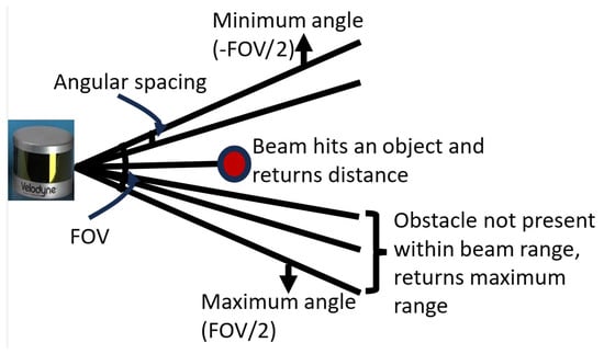
Figure 1. LiDAR sensor parameter definition.
The 2D LiDAR sensors emit laser beams in a single plane (horizontal or vertical) to create a 2D representation of the environment. It measures the time it takes for the laser beam to return after hitting an object, allowing it to calculate distances and generate a 2D point cloud. In contrast to the 2D LiDAR sensor, the 3D LiDAR sensor emits a much larger number of laser beams in multiple directions (usually both horizontally and vertically) to create a volumetric representation of the environment. Sensors with a very high number of beams come with a higher price tag and are, therefore, not cost effective for smaller applications.
Due to the ability of LiDAR sensors to provide a real-time representation of the robot’s environment, they have increasingly been exploited to generate point clouds of the environment for training DRL models for autonomous self-driving vehicles [5,6,7]. For cost effectiveness, researchers typically use 2D LiDAR sensors for small-height robots [8,9,10]. In addition, different researchers randomly select different LiDAR sensors with different beam densities and FOV configurations. Since the DRL model makes decisions based on the information received from the LiDAR sensor, it is important to understand the beam density and FOV required to develop an appropriate learning model. This leads us to ask if a large beam size is required to navigate a static environment.
2. LiDAR Sensor Based on DRL
Collision avoidance and path planning problems have been investigated and solved using many techniques, such as RRT, A, A*, RRT*, and decision trees [11,12,13,14]. These techniques are mostly suitable for applications where the environment state is known and not changing. In a bid to offer a better collision avoidance solution, researchers introduced map localization and position-based methods. In map localization and positioning, cameras are used to capture the state of the environment and detect obstacles and their sizes to determine the path to follow [15]. This usually follows the process of mapping, localization, and planning. In this scenario, as with A, RRT, and related approaches, the environment needs to be known beforehand to design a policy for path planning; hence, it is not best suited for a dynamic environment [16,17,18]. Furthermore, the environment used to develop the model can change over time, and maintaining and updating the models ensures that it can adapt to changes and continue to navigate safely, which is costly, time-consuming, and requires knowledge and experience.
In recent years, the use of reinforcement learning and DRL has increased significantly due to its excellent environmental awareness and decision control performance [19]. The ATAri 2600 [20] and AlphaGo [21] developed by DeepMind are two of the early success stories of RL. In mobile robots, the use of RL/DRL to directly map the state of the environment to the control signal for a dynamic path planning solution remains a challenge. Kasun et al. [22] investigated robot navigation in an uneven outdoor environment using a fully trained DRL network to obtain a cost map to perform the navigation task. The network has prior knowledge of the environment by accepting elevation maps of the environment, the robot poses, and the goal axis as input. Xue et al. [23] and Ruan et al. [24] investigated the use of a double-deep Q-network (DDQN). The size and position of the obstacle and the target position are taken as input to the network, and the robot’s velocity values are output. In [25], a deep deterministic policy gradient (DDPG) algorithm was used to select a control policy for hybrid unmanned aerial underwater vehicles using the robot’s state, LiDAR measurements, and distance to the goal point. A goal-orientated approach to obstacle avoidance was implemented by [26,27]. Their work was based on processing a large amount of depth image information using DRL to reach its goal while avoiding obstacles in a continuous or unknown environment. In another work, Choi et al. [28] proposed the integration of both path planning and reinforcement learning methods to predict the next movement of an obstacle using the calculated distance from the LiDAR information. Wang et al. [29] implemented the curriculum learning of a DRL robot to navigate among movable obstacles. Rather than collecting human demonstrations as in [30], they introduced the use of prior knowledge.
Most collision avoidance models developed using DRL obtain the state of the environment through LiDAR information. When training the learning network, many researchers have used different FOVs (90°, 180°, 270°, or 360°), and the number of LiDAR beams (10–60) has been used by many researchers, which directly impacts the computational complexity of the network [31,32]. Tai et al. [33] developed a navigation learning model in a simulated environment using a 10-dimensional laser beam as one input to the model. Han et al. [34] used the fusion of RGB images from a camera and 2D LiDAR sensor data as input to a DRL network of self-state attention to investigate the effect of using 2D LiDAR on a tall robot. In their work, the training environment is captured and processed before passing it to the training network. Xie et al. [35] applied a proportional-integral-derivative (PID) controller to improve the training rate of a convolutional neural network that takes 512 stacked laser beams as input. In [36], a reinforcement learning method is developed that automatically learns the best number of beams required based on the application. Their work was tested on object detection and shows that the appropriate beam configuration improves the performance of the LiDAR application. Zhang et al. [37] developed a neural network for safe navigation based on different LiDAR sensor configurations (FOV, number of LiDAR sensors mounted and LiDAR orientation). Their work shows that the models with a LiDAR sensor with an FOV of 240° in all scenarios perform better than all other FOVs used. Another work by [38] chooses an FOV with a minimum angle of 13.4° and a maximum angle of 11.5° to train a DRL model for robot navigation. Their approach was able to navigate safely with the limited FOV. Jinyoung et al. [39] investigated the performance of a narrow FOV LiDAR in robot navigation. They developed a navigation model using long-short-term Memory (LSTM), a type of recurrent neural network with a local-map critic (LMC). However, these researchers did not provide details of the criteria used in the selection of these FOVs.
A LiDAR sensor emits light beams to its surroundings, which in turn bounce off surrounding objects back to the sensor. The beam that takes the shortest time to return to the sensor is used to calculate the shortest distance to an impending obstacle, which is further used to control the robot velocity values while training a neural network during navigation. Therefore, it is important to investigate the effect of the LiDAR sensor configuration required to train a DRL based on the required application.
This entry is adapted from the peer-reviewed paper 10.3390/s23249732
This entry is offline, you can click here to edit this entry!