Your browser does not fully support modern features. Please upgrade for a smoother experience.
Please note this is an old version of this entry, which may differ significantly from the current revision.
Subjects:
Engineering, Mechanical
Mechanical vibrational energy, which is provided by continuous or discontinuous motion, is an infinite source of energy that may be found anywhere. This source may be utilized to generate electricity to replenish batteries or directly power electrical equipment thanks to energy harvesters. The new gadgets are based on the utilization of piezoelectric materials, which can transform vibrating mechanical energy into useable electrical energy owing to their intrinsic qualities.
- piezoelectric
- energy harvesting
- renewable energies
- piezoelectric structure
- piezoelectric design
- piezoelectric materials
1. Introduction
The use of electronic devices has grown swiftly and continues to rise rapidly as technology advances. Electronic equipment is often powered by electrical outlets or batteries. The increased use of nonrenewable energy sources, such as batteries, has resulted in increased pollution and the emergence of severe energy crisis scenarios. Batteries have a substantial environmental impact when they are disposed of, in addition to having a limited lifespan that is generally shorter than that of electronic devices. This is an important issue nowadays because, in addition to requiring frequent recharging and replacement, they can also be found in difficult-to-access areas or disrupt the manufacturing cycle. In an industrial environment, for example, replacing batteries in nodes with sensors on machines that monitor the manufacturing process causes downtime, waste that reduces production efficiency, delays, and increased maintenance costs. Consider changing batteries in difficult-to-reach locations such as the middle of the sea or in devices implanted in the human body, as well as the associated expenses. Energy harvesters are considered among the most promising technologies to overcome battery-induced difficulties due to qualities such as miniaturization, high computational power, multi-functionality, and low-power communication [1,2,3,4].
Energy harvesters are devices or systems that gather and transform ambient energy from their surroundings into electrical energy. They are also known as energy scavengers or power harvesters. The energy harvested can be used to power small electronic devices or charge batteries, reducing battery replacement and the need for traditional power outlets. Energy harvesters are especially beneficial in isolated or difficult-to-reach areas where changing or charging batteries is impractical. Energy harvesters range in size and complexity, from micro-scale devices to power sensors to bigger systems capable of generating significant amounts of electricity. Their efficiency is determined by the type of energy source and technology employed. Energy harvesting technologies are being developed and improved by researchers and engineers to make them more efficient, dependable, and usable in a variety of industries, including IoT (Internet of Things), wireless communication, remote sensing, and biomedical applications. The latter, primarily in the form of wearable sensors, enable monitoring of human health and physiological performance by nonintrusive, continuous, and real-time assessment of human physiological parameters [5,6,7,8,9,10,11]. Depending on the type of energy conversion, nanogenerators can be classified as piezoelectric nanogenerators (PENG) [12,13,14], triboelectric nanogenerators (TENG) [15,16,17,18,19], pyroelectric nanogenerators (PYNG) [20], thermoelectric [21,22], and solar cells [23,24].
Depending on the application and energy need, energy harvesters may draw on a variety of environmental energy sources. Figure 1 includes information about each of them [25,26,27,28,29,30].
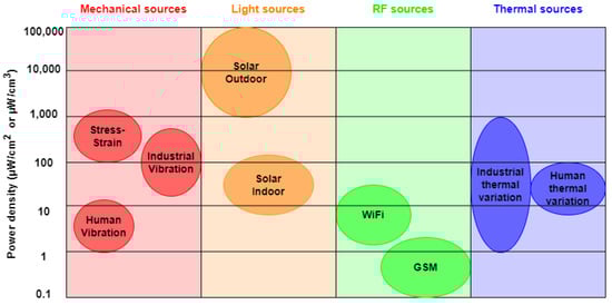
Figure 1. Power density of energy harvested from the different types of energy harvesting sources available.
Mechanical energy is the most common of the sources discussed since continuous or intermittent mechanical motion is an energy that is present and available to everyone in everyday life [31,32]. Mechanical energy harvesters typically use electromagnetic, electrostatic, and piezoelectric systems [32,33,34]. The last environmental energy harvesting technology is the most promising.
2. Harvester Configuration
The creation of the piezoelectric layer structure is a critical component in the design of piezoelectric energy harvesters. A piezoelectric device that uses a vibrational energy source found in the environment may create as much charge on the structure as it can deform. As a result, the main problem is to build a piezoelectric energy harvester that can produce as much energy as possible across a wide range of stress frequencies while still fulfilling mechanical strength and reliability restrictions. During this phase, the support structure or mounting mechanism must be designed to guarantee that the piezoelectric material may flex or deform in response to vibration or mechanical stress. The mechanical interaction between the vibration source and the piezoelectric material should be optimized in the design. The limits imposed by the application and the piezoelectric material in question should be addressed in the design, since the material’s production procedures impose non-negligible dimensional constraints. Structures can be classified into four main categories:
-
Cantilever beam;
-
Circular diaphragm;
-
Cymbal transducer;
-
Stacked array type.
3.1. Cantilever Beam
In most applications, cantilever-type piezoelectric energy harvesters are the most common. The structure with one end embedded and the other free promotes the generation of enormous strains during the excitation of the structure on the limited base. Cantilever beams can be unimorphic or bimorphic, depending on the number of piezoelectric layers linked to the support structure. A piezoelectric foil plus a layer of metallic substance make up the unimorph kind. The bimorph, on the other hand, has a center layer of metal material connected to two layers of piezoelectric material on the top and bottom surfaces. Flexural excitation is chosen in the cantilever beam form since multiple publications demonstrate that the matching “mode 31” piezoelectric connection gives the highest energy conversion efficiency [158,159]. In addition, as illustrated in Figure 5, an extra mass can be supplied to the free end of the cantilever beam to enhance deformation and tune its resonance frequency with regard to the available vibration source [160,161].
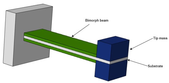
Figure 5. Layout of a common piezoelectric vibration energy harvester.
Substantial contributions to the development of optimal piezoelectric devices that use vibrational energy have been recognized in the literature [45,162,163,164,165,166,167,168,169]. A cantilever beam has several advantages, including low resonance frequencies, high average strain for a given input force, and the ability to be easily generated through a microfabrication process due to its simple form. Yet, a broader study of various design configurations can increase the energy harvesting device’s performance [170,171]. Its functioning concept is based on producing a state of deformation inside the beam, the distribution of which is referred to as butterfly in a general section. It is positive on one side of the tension fiber and negative on the other, fluctuating linearly between these extremes and canceling out on the neutral axis. The bending moment and consequent normal stress in the traditional rectangular scavenger diminish linearly from the fixed end to the free end [172].
According to the uniform strength criterion, a rectangular-plan cantilever beam has a maximum stress strain in the embedment that decreases linearly along the length until it cancels out at the free tip, in contrast to a triangular-plan cantilever beam, which allows for uniform stress distribution along the beam surface. Nevertheless, due to technological limits for production and the area necessary to connect the test mass, the trapezoidal-plan cantilever beam is used as a compromise. This theory is congruent with the application at hand in that it permits the material to retain as much elastic potential energy as feasible. Many studies have been based on this configuration, including [61,173,174]. Roundy et al. [173] present research on piezoelectric energy harvesting designs capable of optimizing power production, as shown in Figure 6.
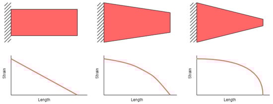
Figure 6. Rectangular and trapezoidal beam comparison.
Figure 7 by Benasciutti et al. [173,174] shows a unique option provided by an inverted trapezoidal construction. When the two constructions, direct trapezoidal and inverse trapezoidal, are compared, the latter greatly increases the stress at the interlock and offers a greater area at the free end, making placing of the test mass easier.
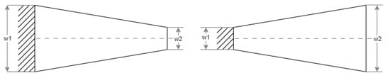
Figure 7. Direct and reverse trapezoidal cantilever.
Mantova et al. [175] investigate the effect of length-to-width ratio on piezoelectric cantilever beams. Long thin beams with a length-to-width ratio greater than one demonstrated the predicted increase in power output when the beam was tapered. In contrast, short broad beams with a length-to-width ratio of 1 indicated a drop in power output when the beam was tapered. Tapering resulted in a more equal stress distribution along the beam surface’s centerline. Tapering has a favorable influence on the mechanical and piezoelectric performance (power) of piezoelectric cantilever binders only if the device beams are long and thin, according to this construction analysis.
Gogoi et al. [176] use a mathematical method to compare the rectangular plan, trapezoidal plan, and T-model, and evaluate the influence of geometrical parameters on the structure’s electrical output performance.
3.2. Circular Diaphragm
A diaphragm is a thin membrane, constructed of a piezoelectric layer, that is used to detect or create sound waves, pressure, or strain. It is made up of a thin piezoelectric disk that is put on a metal plate that is greater in diameter than the piezoelectric disk, Figure 8. A test mass is connected to the middle of the diaphragm to boost power output and intensify performance during low-frequency operation [177]. Piezoelectric diaphragms are commonly found in microphones, loudspeakers, pressure sensors, force transducers, and vibration detecting devices. They are regarded for their sensitivity, ability to work throughout a wide frequency range, and quick reaction capabilities [178].
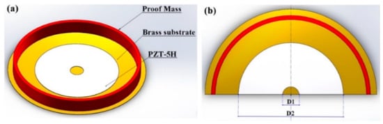
Figure 8. Schematic (a) and parametric (b) structure of piezoelectric circular diaphragm [177].
3.3. Cymbal Transducer
Cymbal transducers, which are effective in situations requiring larger impact pressures, are made up of a piezoelectric layer sandwiched between two metal terminal caps on either side. When an axial stress is applied to the metal terminal caps, it is amplified and turned into a radial stress, resulting in a larger piezoelectric coefficient and, as a result, more charge production by the piezoelectric energy harvester [179]. The plate structure proposed by Newnham et al. [180] is one example. It is made up of two plate-shaped metal end caps with a piezoelectric disk sandwiched between them, as seen in Figure 9. The plate-shaped metal end caps increase the piezoelectric disk’s strength under heavy loads. The metal end caps function as a mechanical transformer due to the existence of a cavity [181].
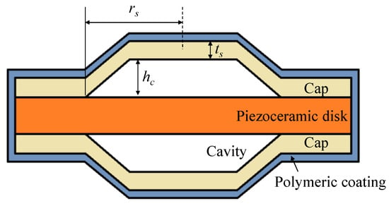
Figure 9. Schematic structure of piezoelectric cymbal transducer [182].
Piezoelectric cymbal transducers are the most widely accessible commercially and may be simply mounted on any flat surface using an adhesive. As a result, several research publications have concentrated on this sort of element in piezoelectric tiles [183,184,185].
3.4. Stacked and Array Structures
Designed for high-pressure applications, piezoelectric stack transducers are made up of several layers of piezoelectric material layered on top of one another with their polarization directions matching the applied force. A piezoelectric array is a grouping of piezoelectric devices that are placed in an array or in a precise sequence for sensing, signal production, or other uses. Piezoelectric arrays are utilized to take advantage of the piezoelectric capabilities of materials in a range of applications, ranging from medical imaging to ultrasound to active vibration reduction in structures. Piezoelectric arrays are essential components of ultrasonic imaging equipment. In this case, the array’s piezoelectric components create ultrasonic pulses that are transferred into the human body. As ultrasonic pulses bounce off inside tissues, the same piezoelectric devices detect the wave’s return and provide a real-time picture.
Chen et al. [186] give a demonstration of an annular piezoelectric array composed of several concentric elements, fabricated by MIP-SL (Mask-Image-Projection-based Stereolithography) technology. The array obtained by printing exhibits stable piezoelectric and dielectric properties. Compared with a conventional single-element ultrasonic transducer, the printed-matrix ultrasonic transducer successfully changes the shape of the acoustic beam and leads to a significant improvement in spatial resolution. In order to optimize the voltage output/electric charge, piezoelectric stacks are utilized [187,188,189,190]. In Cascetta et al. [191], arrays constructed of PZT diaphragm stacks under the top plate were employed to boost the power provided for piezoelectric energy harvesting. To accommodate for deformation, nine piezoelectric diaphragm stacks were employed, each consisting of five piezoelectric diaphragms separated by a ring. The design of a piezoelectric array will thus be determined by the application’s unique sensing or signal generating requirements. Piezoelectric arrays can be used to monitor pressure and detect changes in force distribution on a surface in applications such as vehicle tires or laboratory pressure measurements.
3.5. Other Innovative Configurations
Innovative architectures that increase the efficiency of piezoelectric energy harvesters while maintaining a configuration consistent with the respective field of application have been investigated in the literature over the years.
Ansary et al. [192] suggest fan-folded piezoelectric energy harvesters for powering pacemakers, which comprise bimorph piezoelectric beams folded on top of each other. They demonstrated experimentally that the fan-folded design (shown in Figure 10) may be utilized to lower the high inherent frequency of tiny devices employed in energy harvesting applications.
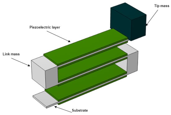
Figure 10. Schematic structure of fan-folded piezoelectric energy harvesters.
Dong et al. propose a piezoelectric spiral energy harvester appropriate for vibrational energy sources in [193,194]. The spiral construction, which is cantilevered at various locations along its circumference, is intended for compactness, low resonance frequency, and low damping coefficient, Figure 11. This option increases compliance in a restricted location by maximizing the length of the cantilever arm. The primary goal of this design is to magnify the input mechanical energy, the transducer of which is the cantilever beam to which this spiral is coupled, considerably increasing the device’s diameter.
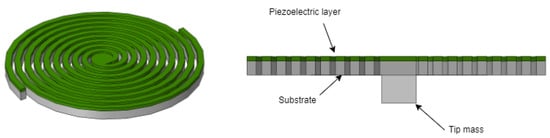
Figure 11. Schematic structure of spiral piezoelectric energy harvesters.
It is crucial to note, however, that this geometry poses some substantial obstacles. One of the most challenging issues is the fabrication stage, which is particularly problematic for single-arm spirals due to residual tensions during the material deposition process, which can cause bending and cracks in the spiral. Moreover, the complexities of electrical charge distribution on spirals need more sophisticated electrode designs. They discovered that the output power is affected by the frequency and direction of the external force, as well as the resistance load.
Castagnetti et al. [195] present an innovative design that makes use of dynamic magnification. It entails attaching the structure to an intermediary spring–mass system that is connected to the vibrating base structure. As a result, the ambient energy that stimulates the structure will intensify the dynamic response and, as a result, enhance the energy provided. This approach is utilized in a number of literary works [196,197,198,199,200]. Figure 12 depicts Castagnetti’s proposed structure, which is inspired by fractals with dynamic magnification.

Figure 12. Structure of fractal geometry with dynamic magnification.
Dong et al. described an in vivo cardiac energy harvesting technique that eliminates contact of the harvesting device with the heart and interference with cardiovascular function [201]. To transfer mechanical energy from the lead of an implantation pacemaker or defibrillator into electrical energy, a piezoelectric energy harvesting device based on a porous thin film with a self-enveloping helical shape was created. Figure 13 shows the similar configuration studied by [202].
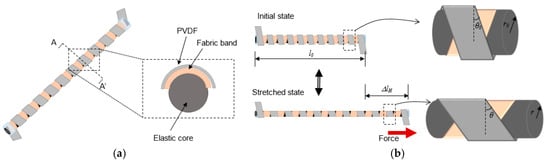
Figure 13. (a) Schematic structure of helical piezoelectric energy harvester and (b) when a stretching force is applied to it [202].
Table 2 summarizes the advantages and disadvantages of the four basic types of configurations for piezoelectric structures.
Table 2. Advantages and disadvantages of piezoelectric energy harvester configurations [44].
| Type of Configuration | Advantages | Disadvantages |
|---|---|---|
| Cantilever beam | Simple structure | Inability to resist a high impact force |
| Low fabrication cost | ||
| Lower resonance frequency | ||
| Power output is proportional to proof mass | ||
| High mechanical quality factor | ||
| Circular diaphragm | Compatible with pressure mode operation | Stiffer than a cantilever of the same size |
| Higher resonance frequencies | ||
| Cymbal transducer | High energy output | |
| Withstands high impact force | Limited to applications demanding high magnitude vibration sources | |
| Stacked and array structures | Suitable for pressure mode operation | High stiffness |
| Higher output from d33 mode |
This entry is adapted from the peer-reviewed paper 10.3390/act12120457
This entry is offline, you can click here to edit this entry!