Lithium–sulfur (Li-S) batteries are considered one of the most promising energy storage systems due to their high theoretical capacity, high theoretical capacity density, and low cost. However, challenges such as poor conductivity of sulfur (S) elements in active materials, the “shuttle effect” caused by lithium polysulfide, and the growth of lithium dendrites impede the commercial development of Li-S batteries. As a crucial component of the battery, the separator plays a vital role in mitigating the shuttle effect caused by polysulfide. Traditional polypropylene, polyethylene, and polyimide separators are constrained by their inherent limitations, rendering them unsuitable for direct application in lithium–sulfur batteries. Therefore, there is an urgent need for the development of novel separators.
1. Introduction
With the rising demand for electric vehicles and portable electronic devices, it is important to research and develop energy storage systems with high energy density, low cost, and extended service life [
1]. Traditional lithium batteries are widely used due to their high working voltage, long cycle life, and good stability [
2]. However, the high production cost, theoretical specific capacity, and low energy density of the electrode material make it difficult for traditional lithium batteries to meet the increasing market scale [
3]. Lithium-sulfur (Li-S) batteries are regarded as one of the energy storage systems with great potential due to its low production cost, high theoretical specific capacity and energy density, abundant S elements in nature, and low toxicity [
4]. They are also facing great challenges, such as the poor conductivity of S elements, the volume expansion of the cathode material, and the shuttle effect caused by lithium polysulfide in the commercial development of Li-S [
5,
6]. Solving the above problems is crucial for the commercialization of lithium-sulfur batteries.
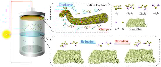
Li-S batteries are composed of an anode, a cathode, an electrolyte, and a separator, as shown in
Figure 1, which represents a schematic diagram of a typical Li-S battery, in which the separator plays a key role in solving the shuttle effect of lithium polysulfide [
7,
8]. The shuttle effect occurs because lithium polysulfide is easily soluble in the electrolyte and moves between the cathode and the anode, resulting in irreversible volume loss [
9]. Therefore, studying a separator with excellent performance is very important in order to solve the shuttle effect.
Figure 1. Lithium–sulfur battery model separator.
2. The Working Principle and Problems of Li-S
2.1. Working Mechanism of Li-S
The electrochemical reactions that occur in Li-S are different from traditional lithium batteries [
17], and the redox reaction during the charging and discharging of Li-S involves the conversion between different valence ions of the S atom, making it more complex than traditional lithium-ion batteries [
18,
19]. Lithium–sulfur batteries generally consist of a lithium metal negative electrode, an organic liquid electrolyte, and a sulfur–carbon composite positive electrode [
20]. Taking a positive electrode material such as sulfur elemental as an example, during discharge, the lithium metal of the anode is oxidized to generate electrons and lithium ions, and the lithium ions diffuse to the cathode through the electrolyte. At the same time, the electrons move to the sulfur element of the cathode through the external circuit, the sulfur element is reduced to S
2−, and S
2− and Li
+ generate Li
2S at the cathode [
21]. During the discharge process, when the sulfur element in the cathode reacts completely with the lithium ion, the total equation of the electrochemical reaction is as follows:
S8+16Li++16e−↔8Li2S
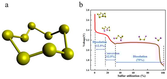
As shown in
Figure 3a, the spatial structure of elemental sulfur is formed by eight sulfur atoms connected by covalent bonding, so there are multiple cleavage and bonding sites of S-S bonds in sulfur elements, resulting in more complex redox reactions in the charging and discharging process of Li-S [
20,
22]. At present, there are many studies on the S conversion of lithium–sulfur battery charging and discharging process [
22,
23]. According to the measurement of the electrolyte mass spectrometry (LC/MS) of different charges and discharges, the reduction reaction of elemental sulfur is carried out in multiple steps, and there are a variety of different intermediate products, such as Li
2S
8, Li
2S
6, Li
2S
4, Li
2S
2, Li
2S
2, and Li
2S [
24].
Figure 3. (a) Schematic diagram of the spatial structure of elemental sulfur. (b) Red is the discharge curve of lithium-sulfur battery, showing the sulfur electrode utilization.
When discharging, the electrochemical reaction is as formulated (2)–(6) [
17]:
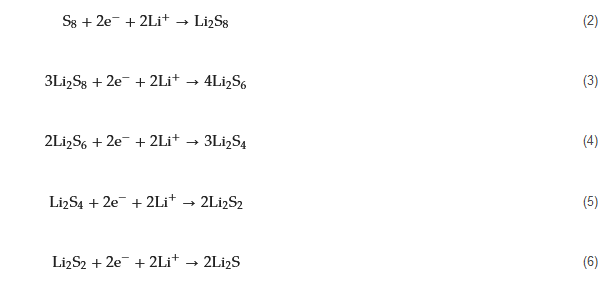
As can be seen in
Figure 3b, it can be seen from the discharge curve of the Li-S that there are two discharge platforms in the discharge process [
25]. The high discharge platform is between 2.3~2.4 V; at this time, the S8 product is a variety of soluble long-chain lithium polysulfide Li
2S
x (4 ≤ x ≤ 8) [
26]. The low discharge platform is between 1.8~2.1 V; at this time, the corresponding long-chain lithium polysulfide Li
2S
x (4 ≤ x ≤ 8) is further reduced to short-chain lithium polysulfide Li
2S
x (1 ≤ x ≤ 4) [
27] (Wu et al. [
28]). According to experimental calculations, the utilization rate of the active material of the high discharge platform is only 25%, and the theoretical capacity of the process is 418 mAh g
−1. The active material utilization rate of the low discharge platform is 75%, and the theoretical capacity of the process is 1254 mAh g
−1. At the low discharge platform, due to the growth of lithium dendrites and phase transition processes, the reaction kinetics of this process slow down, and the actual discharge-specific capacity of the battery is lower than the theoretical capacity, so the actual specific capacity of the Li-S is lower than the theoretical specific capacity throughout the entire discharge process [
29,
30,
31,
32].
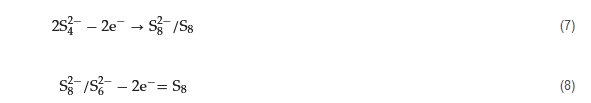
When charging, there is only one noticeable platform of about 2.4 V [
33]. Electrochemical reactions can be described by Formulas (7) and (8):
2.2. The Existing Problems of Li-S
2.2.1. Cathode
Because sulfur resources are abundant, non-toxic, and non-polluting; the theoretical specific capacity is 1675 mAh g
−1; and they have low prices and other advantages, sulfur was selected as the cathode material in Li-S batteries [
34,
35,
36]. However, problems such as low conductivity, volume expansion during electrochemical reactions, and shuttle effect lead to low coulombic efficiency, and the actual specific capacity is much lower than the theoretical specific capacity, in addition to poor cycle stability [
37].
2.2.2. Separator
As a vital part of Li-S, separators play a great role in the performance of Li-S [
41]. During the charging and discharging process of lithium–sulfur batteries, the separator does not directly participate in the electrochemical reaction of mutual conversion between polysulfides [
42]. However, the wettability, thermal stability, mechanical properties, porosity, liquid absorption rate, and other properties of the separator affect the specific capacity and cycle life of the Li-S. As a separator for Li-S, it is not only necessary to maintain the advantages of wettability, thermal stability, mechanical properties, porosity, and liquid absorption rate [
43], but also to effectively suppress the shuttle effect [
44].
2.2.3. Anode
The weight density is low, and the theoretical specific capacity is 3860 mAh g
−1 higher [
45]. Due to its low reduction potential [
46,
47] and other advantages, lithium metal was chosen as the electrode material for Li-S. Metallic lithium is used as an anode in Li-S [
48] due to the growth of lithium dendrites [
40,
49,
50,
51]. Lithium dendrites easily pierce the separator, resulting in potential safety hazards in the circuit. Lithium metal itself has strong activity and can easily have side reactions with electrolytes, resulting in low battery cycle life and other problems that limit the commercial development of Li-S.
2.2.4. Electrolyte
Electrolytes, as a pivotal constituent bridging the positive and negative electrodes, wield substantial influence on the transport of lithium ions, thereby exerting a direct impact on the performance of lithium–sulfur batteries. Electrolytes can be classified into two categories: liquid electrolytes and solid electrolytes.
Presently, liquid electrolytes find extensive application in lithium–sulfur batteries, primarily owing to their facile synthesis, high ionic conductivity, and favorable chemical stability. Nevertheless, liquid electrolytes are not without their challenges. Firstly, at the positive electrode, liquid electrolytes tend to dissolve polysulfides, which subsequently diffuse through the electrolyte to the negative electrode, leading to diminished Coulombic efficiency and corrosion of the lithium negative electrode. Secondly, liquid electrolytes typically comprise flammable organic solvents, thus posing safety concerns when exposed to elevated temperatures. In response to these issues associated with liquid electrolytes, a substantial body of researchers is actively engaged in addressing these challenges. This includes the modification of electrolyte composition, the exploration of novel multi-component solvents, and the incorporation of functional additives [
58].
2.2.5. Binders
Binders, constituting an integral part of the sulfur cathode in lithium–sulfur batteries, serve the crucial function of ensuring effective electrochemical contact among the conductive agent, sulfur, and current collector. Moreover, they mitigate volumetric variations of active materials during cycling. Binders play a pivotal role in lithium–sulfur batteries, and the commonly utilized types encompass polymeric, bio-based, and inorganic binders. Challenges regarding binders encompass inadequate mechanical properties and the detachment of electrode materials during cycling, consequently leading to a diminished cycling lifespan and reduced stability of the battery.
2.2.6. Current Collector
Aluminum foil has found widespread application as a current collector for sulfur cathodes. However, at elevated temperatures, aluminum and sulfur can undergo reactions, which may pose safety concerns. Presently, the use of carbon-coated aluminum foil is employed to mitigate direct contact between sulfur and aluminum foil, thereby enhancing the safety of lithium–sulfur batteries. The presence of carbon coatings effectively improves the adhesion between the active materials and the current collector, while simultaneously enhancing electrical conductivity [
60].
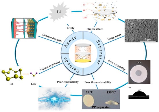
Figure 4. Existing problems with lithium–sulfur batteries [
61]. Reproduced with permission from the Polymers.
3. Methods
With the development of science and technology, separator technology has also been continuously developed and updated, and the methods of preparing polymer separators have also been diversified. Different preparation methods can be selected according to the material properties and separator application direction. The battery separator film is closely related to the energy density, stability, and cycle life of the battery [
62]. A battery separator composed of nanofibers has the advantages of a large specific area and high porosity [
63], which has attracted close attention. There are many methods of separators, but electrospinning [
64], vacuum filtration [
65], wet spinning [
66], the coating method [
67,
68], the in situ growth method [
69], and atomic layer deposition [
70] are more commonly used to prepare separators.
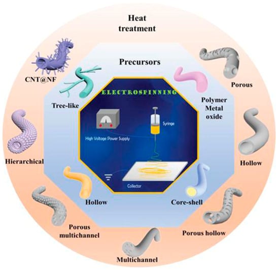
3.1. Electrospinning
Electrospinning is a novel technique for preparing nanofiber separators, the principle of which is as follows:: under the action of a high-voltage electrostatic field, the polymer forms a Taylor cone when it flows out of the needle, and a continuously charged jet is ejected and deposited on the collector as nonwoven nanofibers [
71]. The nanofibers prepared by electrospinning can reach the nanometer diameter [
64,
72], and the prepared nanofiber separator has the advantages of high porosity, large specific surface area, and small pore size [
73]. As shown in
Figure 5, electrospinning technology has prepared a variety of nanostructured fibers. The electrospinning method has received great attention in the field of battery separators in recent years.
Figure 5. The electrospinning technology has prepared a variety of nanostructured fibers [
2]. Reproduced with permission from the Advanced Functional Materials.
3.2. Vacuum Filtration
The vacuum filtration method is a new method for preparing separators using the interfacial composite method, which has the advantages of convenient operation, a simple process, and no specific process equipment. Its working principle is that the film-forming material is uniformly dispersed in the solvent, and then under vacuum filtration conditions, the film-forming material is deposited on the substrate due to the flow function of solvent molecules. The disadvantage is that due to the limitations of process conditions, the structure of the produced nanofibers is uncontrollable and unsuitable for large-scale mass production [
74].
3.3. Wet Spinning
The nanofiber non-woven separator prepared by the wet laying method has high porosity and good affinity with electrolytes [
75]. The principle is that different polymer fibers are used to separate matrix fibers and adhesive fibers, which are continuously randomly laid on the screen belt after mixing in a water-soluble suspension, sent to a ventilation drying box to heat and soften the bonded fibers, and then calendered by a heating drum to obtain a non-woven film [
62]. The disadvantages are that the structure and properties of the nanofibers prepared by this method are limited by the type and composition of the polymer in the suspension, and the operation is more complicated [
76].
3.4. Coating Method
The coating method is one of the most commonly used modification methods. A layer of modified material is coated on one side of the separator by means of physical methods, and polysulfides are adsorbed by the modified material to improve the shortcomings of the separator. Because the coating method is simple to operate, relatively low in cost, can be used for large-area separator modification, and is suitable for industrial production, the coating method is widely used in the modification of lithium–sulfur battery separators. However, the coating method has problems such as difficulty in accurately controlling the thickness of the separator. The viscosity of the material has an impact on the coating effect, and some polymer materials are not suitable for the preparation of the coating method.
3.5. In Situ Growth Method
The in situ growth method is a relatively novel method of separator modification. Compared with other modification methods, this method can effectively generate a lightweight barrier on one side of the separator and avoid excessive thickness of the separator; in addition, the in situ growth method can achieve efficient use of materials, thereby reducing costs. However, the current in situ growth method is still in the experimental research stage. In addition, the modification process is relatively complicated, and it is difficult to achieve mass production.
3.6. Atomic Layer Deposition (ALD)
Atomic layer deposition is a method in which substances can be plated on the surface of the substrate, layer by layer, in the form of a single-atom film. It has similarities to chemical vapor deposition [
77]. Its working principle is a method in which a gas precursor pulse alternately enters the reactor and chemically adsorbs and reacts on the deposition matrix to form a deposition film. A typical ALD cycle consists of two self-limiting semi-reactions [
78], and it is this reaction property that allows the separator’s thickness to be precisely controlled. However, the atomic layer deposition method has disadvantages such as high requirements for reaction conditions, a complicated production process, expensive equipment, and a slow deposition rate.
4. Application of Separators in Lithium–Sulfur Batteries
4.1. Electrospinning
4.1.1. Separator
In Li-S, the separator is required to suppress the shuttle effect, good electrolyte wettability, and good ionic conductivity [
79]. Nanofiber separators prepared using the electrospinning technique exhibit extremely fine fibers, with exceptionally high specific surface areas. Additionally, these separators possess a notably high level of porosity, a feature inherent to their unique fabrication process. Owing to their elevated specific surface areas and porosity, such separators can provide a greater quantity of electrolytes during the charge and discharge processes of lithium–sulfur batteries. This augmentation of reaction sites enhances electrochemical reactions. In recent years, numerous researchers have achieved significant advancements by incorporating modified materials onto the fiber surface, aiming to adsorb polysulfides and mitigate the shuttle effect, thereby improving the cyclic lifespan and practical specific capacity of the batteries (Guo et al. [
80]).
4.1.2. Interlayer
A highly conductive electrospun nanofiber interlayer is introduced between the positive electrode and the separator to effectively improve the performance of lithium–sulfur batteries. Electrospun carbon nanofibers, owing to their excellent electrical conductivity, serve to reduce internal resistance within batteries, thus enhancing the rates of electron and ion transport. Additionally, carbon nanofibers exhibit Van Der Waals interactions with polysulfides, facilitating their adsorption. Guo et al. [
81]. utilized electrospinning technology to prepare a Ti
4O
7/C nanofiber (TCNF) interlayer. The incorporation of carbon nanofibers in this interlayer offered several advantages, including a large specific surface area and high electrical conductivity, which significantly enhanced the conversion and electron transfer of polysulfides. Additionally, Ti
4O
7 formed strong chemical bonds with polysulfides, effectively mitigating their shuttle effect.
4.2. Vacuum Filtration
4.2.1. Separator
According to Yigeng et al. [
89], They modified the PP separator through suction filtration, a depositing a layer of g-C3N4 composite on one side of it. It had abundant adsorption sites and contributed to the solidification of polysulfides. The process of polysulfide solidification entails immobilizing polysulfide species onto the cathode material or the cathode-proximate regions of the separator. This strategic immobilization serves as an effective countermeasure against the undesirable migration of polysulfides towards the anode, thereby mitigating capacity fade and consequentially augmenting the performance characteristics of lithium–sulfur batteries.
4.2.2. Interlayer
Feng et al. [
90] prepared a 2D NiCo MOF/CNT as the middle layer of a lithium–sulfur battery and filtered it onto PP through vacuum filtration. The thickness of 2D NiCo MOF/CNT was only a few nanometers, and the CNT built a conductive network to enhance electronic conductivity while serving as a physical barrier to prevent polysulfide migration. The 2D NiCo MOF/CNT improved the catalytic performance due to abundant and accessible active sites. The lithium–sulfur battery using 2D NiCo MOF/CNT interlayer had an initial discharge-specific capacity of 1132.7 mAh g
−1 at 0.5 C, and it maintained 709.1 mAh/g
-1 after 300 cycles, showing good cycle stability and rate performance.
4.3. Wet Spinning
Currently, commercial PP and PE separators are prepared using a wet process. However, when used directly in lithium–sulfur batteries, the PP separator leads to a significant shuttle effect, resulting in a sharp decrease in the specific discharge capacity of the battery. Main applications include functional interlayers in Li-S [
18,
97,
98,
99,
100] and electrodes [
101,
102]. Li et al. [
98] successfully prepared a carbon paper sandwich via a wet process with excellent electrical conductivity of 11.9 S cm
−1. A high initial capacity, up to 1091 mAh g
−1, was achieved when using carbon paper as an interlayer for Li-S. At 5 C, 631 mAh g
−1 was maintained after 200 cycles (0.21% capacity decay per cycle).
4.4. Coating Method
4.4.1. Separator
Polar metal oxide titanium dioxide (TiO
2) exhibits a strong chemical interaction with polysulfides, making it widely applicable in the field of lithium–sulfur batteries. This is attributed to the ability of oxygen atoms on the surface of TiO
2 to form chemical bonds with sulfur atoms present in polysulfides, facilitating the effective adsorption of polysulfides. Additionally, the high electronegativity of the TiO
2 surface enables it to counteract the shuttle effect of polysulfides through a charge repulsion mechanism. Gao et al. [
57] coated the PP separator with a layer of titanium dioxide, modified multi-walled carbon nanotube composites (TiO
2@SCNT/PP separator), and applied the separator to Li-S, and the data showed that the performance of the separator and the pre-modification period greatly improved.
4.4.2. Interlayer
Wang et al. [
104] prepared the NC-Co interlayer using a coating method. The intermediate layer effectively inhibited the shuttling of polysulfides. At 1 C, the first discharge-specific capacity of the lithium–sulfur battery using the interlayer was 1216.9 mAh g
−1, and it maintained 660.3 mAh g
−1 after 250 cycles. The Coulombic efficiency remained above 99% during the cycle. After 100 cycles, the surface SEM of the negative lithium metal showed that the lithium negative electrode with the interlayer had few surface cracks, while the lithium metal without the interlayer had obvious cracks, indicating that the use of the interlayer can significantly inhibit the corrosion of the negative metal lithium.
4.5. In Situ Growth Method
4.5.1. Separator
Lu et al. [
111] modified a PP separator via in situ growth. On the side of the PP separator, a layer of polar hydrated sulfate CoSO
4·4H
2O material (CS/PP separator) was grown in situ, and the cobalt sulfate hydrate had strong polarity and catalytic properties, which can effectively adsorb polysulfides. In the preparation flow chart, it can be seen by scanning electron microscopy that the surface of the separator was attached to a layer similar to the shape of a sea urchin, the single sea urchin was assembled from the nanoneedles of several microns, and the separator exhibited good mechanical stability. The data show that when the material reaction time was 6 h, the separator showed the best performance, which was denoted as CS/PP-6. At 1 C, the initial specific capacity of the modified separator reached as high as 807.7 mAh g
−1. After 500 cycles, it still maintained 504.6 mAh g
−1 (compared to 208.7 mAh g
−1 for the PP separator), and the Coulombic efficiency reached as high as 97%. When the discharge current was restored to 0.1 C, the reversible capacity was 1308.6 mAh g
−1, indicating that the lithium–sulfur battery using the separator had good reversibility and good electrochemical performance.
4.5.2. Interlayer
Li et al. [
112] prepared the ZIF/CNFs interlayer via the situ growth method. The interlayer had an obvious effect of inhibiting polysulfide shuttling. According to SEM and TEM images, ZIF-64 particles were distributed on the fiber, and due to the special binding site of ZIF-64, it inhibited the shuttling of polysulfides during circulation. At 1 C, it exhibited a high discharge-specific capacity of 1334 mAh/g, which remained at 569 mAh/g after 300 cycles.
4.6. Atomic Layer Deposition
4.6.1. Separator
At present, owing to the distinctive attributes of the Atomic Layer Deposition (ALD) fabrication process, there is a scarcity of literature that directly employs ALD for the modification of polypropylene (PP) separators. Usually, people use methods such as cooperating with other preparation processes (coating, suction filtration, etc.) to modify the separator.
4.6.2. Interlayer
Lin et al. [
70]. prepared the CNT@SACo interlayer by atomic layer deposition and applied it to lithium–sulfur batteries. From the experimental results, the CNT@SACo interlayer exhibits catalytic activity catalyzes the conversion of polysulfides, and inhibits the shuttling of polysulfides. The lithium–sulfur battery with the CNT@SACo interlayer exhibited a high discharge specific capacity of 880 mAh/g at 1 C, and maintained a capacity of 595 mAh/g after 500 cycles, with a capacity decay rate of 0.064% per cycle.
5. Conclusions
In recent years, with the rising demand for new energy, it has become important to develop an energy storage system with high energy density, low cost, and a long cycle life. Traditional lithium batteries have a high cost and low energy density, which makes it difficult for them to meet the huge market demand. Li-S batteries are regarded as one of the most promising energy storage systems due to their high theoretical specific capacity and low cost. Li-S batteries also have some urgent problems to solve, such as poor conductivity of S, the expansion of the positive electrode volume during the electrochemical reaction, and the most important problem, the shuttle effect caused by polysulfides. As an important component of lithium–sulfur batteries, separators are very important in suppressing the shuttle effect of polysulfides.
This entry is adapted from the peer-reviewed paper 10.3390/polym15193955