The general requirement of precision motion in manufacturing and other commercial devices has led to extensive research and development in precision engineering. Having emerged as an integrated domain, precision engineering focuses on movement, measurement, and maintaining precision motion with higher accuracy and repeatability [
1,
2,
3]. Piezoelectric actuators have been extensively used over the past few years as a source of precision positioning in a wide range of commercial applications. Piezoelectric actuators offer the advantage of precision motion in a few nanometers range to the tens of micrometer range. Furthermore, the faster response, low voltage actuation, high stiffness/load capacity/force generation smooth, backlash-free motion, non-magnetic actuation, wear resilience, cleanroom compatibility, vacuum, and cryogenic condition, low energy consumption adds to the advantages of the piezoelectric actuators [
4,
5,
6]. Typical application domains of the piezoelectric actuators include precision manufacturing, fluidic applications, medical technology, micro-optics, aviation, defense, automation, robotics, aerospace, and consumer electronics.
Piezoelectric actuators are effectively employed in different applications such as micropumps/microreactors/micromixers [
7,
8], micromanipulators [
9,
10], microvalves [
11], micro jet dispensers [
12,
13], atomic force microscopes [
14,
15], tool feed mechanisms [
16,
17], vibration isolation systems [
18], etc. Piezoelectric actuators suffer from system nonlinearity when operated under dynamic conditions despite many advantages. The inherent hysteresis and creep limit the performance of the piezoelectric actuators under dynamic conditions, leading to nonlinearity in the system. Moreover, a badly damped system leads to undesirable vibrations, which add to the nonlinearity [
4,
19,
20].
2. Overview of the Piezoelectric Actuation System
Piezoelectric actuators are a class of electromechanical devices that convert electrical signals to precise, controllable displacement. Typically, piezoelectric actuators are made of a group of smart materials that possess the property of piezoelectricity due to electromechanical coupling, which produces electric charge or mechanical strain based on the input stimulus [
21]. When subjected to an external force, the piezoelectric materials produce electric charges corresponding to the direct piezoelectric effect. The application of piezoelectric materials as precision actuators adopts the inverse piezoelectric effect, which develops mechanical strain based on the applied electric potential, which in turn produces precision motion [
21,
22,
23]. The early stage of discovering piezoelectric materials constituted quartz, Rochelle salt, and tourmaline, producing a comparable piezoelectric effect. However, the commercial need for large-range precision motion led to the discovery of synthetic piezoelectric materials such as Lead Zirconium Titanate (PZT) [
24], Barium Titanate (BaTiO
3) [
25], PVDF [
26], ZnO [
27], etc.
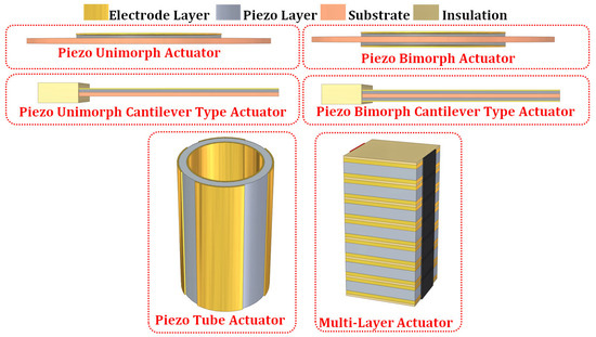
Figure 1 represents the basic configuration of the piezoelectric actuators used in different applications. The basic configuration of piezoelectric actuators is unimorph and bimorph, wherein the single-layer or two-layer piezo materials are bonded onto the metal substrate [
28,
29]. The unimorph and bimorph actuators are also available in a cantilever configuration, which is more flexible and produces a significant range of motion. However, the cantilever configuration lacks generated force [
30,
31]. The piezoelectric tube actuators can generate linear or lateral motion and are effectively adopted in many precision motion applications [
32,
33]. The multi-layered stacked configuration of the piezoelectric actuators can operate in linear or shear mode to produce linear or lateral precision motion. The range of motion developed by the stacked configuration is limited; however, the blocked force generated has an advantage over other types of actuators [
5,
21,
34,
35]. The amplified piezo actuators are developed with a flexural-compliant structural member to enhance the deflection of the stacked piezo actuators. Flexural-based amplification enhances the deflection range of the stacked actuators with moderate force [
36,
37]. Typically, the amplified piezo actuators in elliptical type, rhombus type, bridge type, symmetric five bar type, honeycomb type, Scott–Russell type, and lever type are extensively used in precision positioning applications [
21,
38,
39,
40,
41].
Figure 1. Basic configurations of the piezoelectric actuators.
Further advancement in piezoelectric actuator technology led to the development of stepping-piezoelectric actuators intended to generate a broader range of bi-directional linear and rotary motion. The stepping configuration of the piezoelectric actuators is also known as the piezo motor, which typically involves traditional piezoelectric actuators such as the unimorph/bimorph/multi-layered stacked actuators and the amplified piezo actuators as the primary source of actuation [
21,
42,
43]. Inchworm piezoelectric motors [
21,
44,
45], inertial piezoelectric motors [
21,
46,
47], and ultrasonic piezoelectric motors [
21,
48,
49] have been extensively reported in recent years which are effective in fulfilling the need of large range stepping motion. These piezoelectric motors can produce either linear/rotational motion or both, depending on the design and arrangement of the primary piezoelectric actuation mechanism. Researchers have also developed a series/parallel arrangement of multiple piezoelectric stepping stages to achieve multi-degree freedom linear/rotational motion along different coordinates [
50,
51]. A detailed review of different configurations of traditional, stepping, and multi-degree freedom piezoelectric actuators are presented in the works of Mohith et al. [
21], Jianping Li et al. (2019) [
52], Liang Wang et al. (2019) [
53], and Shupeng Wang et al. (2019) [
54].
The traditional piezoelectric actuators such as unimorph, bimorph, tube, and multi-layered actuators are a primary source of precision actuation in many commercial actuation systems. The constitutive Equations (1) and (2) represent the piezoelectric phenomena occurring in piezoelectric actuators is represented as follows [
55] (IEEE Ultrasonics, Ferroelectrics, and Frequency Control Society)
where
σ and
ε correspond to the stress tensor and strain tensor,
D and
E correspond to the vector representing the electric displacement and the electric field,
d represents the piezoelectric material constant,
eE the elastic compliance matrix,
ϵT represents the dielectric constant,
i,
j = 1, 2, 3, 4, 5, 6 and
m,
k = 1, 2, 3 refers to the different directions in the Cartesian coordinates. As observed in Equations (1) and (2), the mechanical strain developed in the piezoelectric materials follows a linear relationship with the applied electric field. However, when the piezoelectric actuators are put into operation under dynamic conditions, there exist system nonlinearities that affect the performance of the piezoelectric actuators. Therefore, there is a need for better modeling and control approaches that can model the inherent system nonlinearities of the piezoelectric actuation systems and minimize the error occurring due to nonlinearity through appropriate compensation models and control strategies.
3. Comprehensive Dynamic System Model and Modeling/Control Issues of the Piezoelectric Actuator
The promising potential of piezoelectric actuators has led to their application across wide ranges of precision manipulation to the extent of the nanometer scale. However, the dynamics of the piezoelectric actuator in specific applications lead to inherent nonlinearity that causes positioning errors. Thus, the development of modeling and control strategies for minimizing the nonlinearity errors in piezoelectric actuators have been given considerable attention. The constitutive relationship of piezoelectric materials (Equations (1) and (2)) does not account for any dynamic nonlinearity in the piezoelectric actuators. The nonlinearity emanates from hysteresis and creep, which significantly degrades the performance of the piezoelectric actuators in dynamic applications. Moreover, a badly damped system with piezoelectric actuation leads to dynamic vibrations, adding to the system’s nonlinearity [
55,
56].
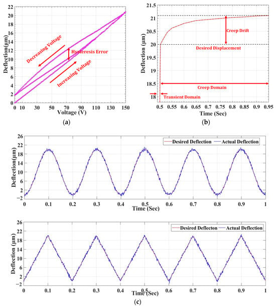
Figure 2 represents the schematic of nonlinearity occurring in the piezoelectric actuators due to hysteresis, creep, and vibration. Hysteresis in the piezoelectric actuators occurs due to specific extrinsic contributions that induce nonlinearity between the actuation voltage and precision output displacement. The extent of hysteresis error depends on the present value of the input voltage and the previous history, thus developing a memory-based phenomenon. The amplitude and the frequency of the actuation signals majorly affect the extent of hysteresis error occurring under the dynamic operation of the piezoelectric actuators. Thus, the hysteresis in piezoelectric actuators shows either amplitude-dependent or rate-dependent behavior. The model approximating the hysteresis is either rate-dependent or rate-independent [
56,
57,
58,
59,
60,
61,
62]. The piezoelectric actuators under dynamic operation experience hysteresis error of about 15%, but with the increase in the driving frequency of the actuation signal, the error can shoot up to almost 35%, thus leading to the error in precision motion [
55].
Figure 2. Schematic representation of the nonlinearity in the piezoelectric actuators due to (a) hysteresis, (b) creep, and (c) Vibration.
The creep in the piezoelectric actuators occurs due to the effect of applied electric potential on the remnant polarization of the electric dipole. The root cause for creep drift is the realignment of the crystal structure on the application of the electric field. The effect of creep drift significantly occurs at a low speed of operation and leads to a broad range of nonlinearity with the increase in time [
55,
56]. The combined effect of hysteresis and creep hinders the performance of the piezoelectric actuators in precision positioning applications where higher accuracy and precision are the significant criteria [
57,
58,
59,
60,
61,
62]. Implementing an appropriate modeling approach can model the piezoelectric actuator system behavior under hysteresis and creep, which can provide suitable compensation by adopting proper control approaches to overcome the nonlinearity errors.
The piezoelectric actuators are modeled as a combination of electrical and mechanical systems based on the electromechanical interaction at different stages [
63,
64,
65].
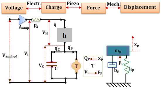
Figure 3 represents the schematic of the electromechanical model of the piezoelectric actuator. Goldfarb et al. [
63] developed and implemented the following electromechanical model of the piezoelectric actuator with hysteresis nonlinearity. Adriaens et al. [
64] also adopted a similar approach in defining the electromechanical model of the piezoelectric actuator with hysteresis. Gao et al. [
63] proposed a linear modeling approach with the electromechanical interaction, which excluded the effect of nonlinearity occurring due to hysteresis.
Figure 3. Schematic representation of the electromechanical model of the piezoelectric actuator.
Mathematically the comprehensive dynamic model of the piezoelectric actuator can be written as shown in Equations (3)–(9)
where
Vapplied is the control voltage fed through a linear amplifier of gain
Aamp,
Ri is the overall resistance of the driving circuit.
Vi is the amplified voltage that drives the piezo actuator,
q and q˙ are the total charge and current through the circuit,
H and
T represent the hysteresis and electromechanical piezo coefficient with corresponding voltage drop
VH,
VT, and
C corresponds to the total capacitance of the piezoelectric circuit which stores charge
qc. The piezoelectric effect induces a charge of
qP across the transformer element
T. The conversion of the applied voltage across the piezoelectric element induces force
FP with the piezoelectric element of mass
mP, stiffness
kP, and damping coefficient of
bP, resulting in the displacement of
xP.