Your browser does not fully support modern features. Please upgrade for a smoother experience.
Please note this is an old version of this entry, which may differ significantly from the current revision.
By progressively embracing the general principles of integrated, parametric, interdisciplinary design that considers the manufacturing elements of the imagined product, the modern aesthetic designer is called upon to broaden their knowledge and abilities. Especially when there is a need to produce complex shapes, when cost-effective, there are also numerous 3D printing technologies available today, to be used both in the conceptual phase (prototyping) and for actual production.
- aesthetic design
- parametric modelling
- product engineering
- CAD
- generative design
- topology optimisation
1. Introduction
As widely recognised, the term aesthetics is related to both what the product presents to the senses (especially vision) and the process of regarding an object [1]. In contrast, functionality indicates how a product can serve its goal [2] by ensuring a set of required mechanical/technical properties, under specific constraints. Since a product’s success is commonly correlated with its capacity to strike an ideal balance between aesthetics and functionality, these two seemingly opposite concepts must find a meeting point during product design and production. For the aesthetic designer, developing a novel product and considering its functionality is like playing solitaire with cards: often there is no counterpart as in other projects and furthermore, there is no dialectical relationship with the customer, the engineer or the technologist. The creative person is “alone with himself” and required to set the rules of the game, drawing from their own reservoir of skills, not necessarily complying with engineering design and manufacturing. This is what makes the designer’s game more challenging, but also more exciting [3], especially when creativity and stylistic innovation are predominant in the creation of the product. However, this kind of design methodology is an exception, defining only a tiny fraction of the whole design industry and typically being restricted to the creation of luxury goods [4]. The search for an original, iconic, and distinctive design represents, in these cases, the main interest of the company, which is willing to give up many technical compromises in order to ensure a unique product capable of adding value to the entire brand.
In reality, in most cases, the designer is forced to confront a series of constraints dictated by all the technological aspects that must be considered when designing a successful product. These include the need to imagine a product that is able to respect functional requirements without sacrificing aesthetics at the same time [5], such as the manufacturability of the components, competitiveness in terms of performance compared to the competition, scalability of production, and the need to reduce costs.
All these elements contribute in different weights to the success of the product and must be integrated as organically as possible within it. Ultimately, to ensure a high value of the product imagined by the designer, the design activity must be able to integrate the concept design, where forms, layouts, operating principles, and sensory, perceptive and emotional properties are defined, with the embodiment and detailed design phases where technical acts such as construction drawings, models, choice of materials, and choice of production process impact on the final realisation. In the best-case scenario, the aesthetics of the product should lead to the definition of forms that also reinforce the technical aspects and are of interest to a buyer. The realisation of forms that, while iconic, are easily produced with either traditional technological processes or the most modern 3D printing tools, leading to material savings, or capable of significantly improving the performance of the object studied, is an established goal for the modern designer.
In large companies, characterised by major brands, the synthesis of these several aspects of product planning is achieved through the integration of dedicated teams characterised by very different profiles of experience and skills. Through concurrent planning [6], i.e., an organic set of methodologies, techniques, and tools that allows an integrated approach to the design of a product and its production process, it is possible to effectively achieve the desired objective.
The case of significantly smaller realities is different. Smaller design studios, individual aesthetic designers, and planners must be able to conduct the described synthesis process without being able to draw on the different experiences of a team of specialists in different fields. In this context, the experience of the aesthetic designer, together with their creativity, is the main driver towards a successful solution. Unfortunately, given the vastness of design activities, the building of a personal wealth of knowledge is in any case a complex and prolonged activity, which cannot, over time, keep up with the demands of product innovation in view of the development trend offered by the state of the art.
The design education of new industrial designers must clearly aim for the formation of a critical spirit, the construction of a design methodology, and the definition of a unique style [7]. At the same time, however, the training must provide for the transmission of a set of basic technical skills, which the designer can draw on to assess the manufacturing and functional aspects of the product, as well as the tools and methods necessary to manage the value chain in the innovation aspects of industrial design and related processes. Technical drawing, mechanical technology, design under static and dynamic loads, evolutionary design, product end-of-life management, and circular economy [8] are the main aspects that every designer should include in their knowledge from the very beginning of their career.
In the absence of an adequate level of technical background, the search for this synthesis is characterised as the greatest difficulty for young aesthetic designers who have not yet accrued a wealth of skills to guide them in functional design. For this reason, the search for concrete solutions, in which the aspects of manufacturability, structural, and other accessory functions (interface with man, ergonomics, and usability) are often hindered by the definition of forms that are difficult to concretise and linked in the foreground to aesthetic aspects alone. This phenomenon is stimulated by the introduction of surface modellers, which do indeed leave the user great freedom in defining complex and interesting geometries, shapes, and topologies, but do not allow aspects relating to the functionality and actual realisability of the product to be assessed in advance. Secondly, despite the propensity of young design students to use smart technologies, the “disconnection” between digital design and effective manufacturability of the conceived product has introduced new barriers and exacerbated the gap described above.
2. Product Engineering Modelling in Aesthetic Design Education
2.1. The Role of Parametric Modelling in Aesthetic Design Education
The range of CAD modelling software currently available on the market is diversified. By analysing the various CAD modelling systems, it is possible to identify significant differences in the operating logic and performance offered to the user. As widely recognised, the main distinction that can be made is between non-parametric and parametric CAD systems. The former does not consider the temporal succession of operations made by the user to arrive at the desired result (which is identified in the modelling history of the model). The latter, on the other hand, does keep track of this type of data. Traditionally, the term ”parametric modelling” refers to CAD logic that keeps track of the modelling functions used by the user and the relationships and constraints imposed. Conversely, “non-parametric” modelling only considers the last configuration of the digital model modified by the user and allows interaction with this, but not with the models resulting from previous operations.
Both strategies present advantages and disadvantages: on a general level, non-parametric modelling is usually more intuitive, requires less knowledge of the modelling environment within which one moves, and is easier to manage by the software, which does not have to keep track of many parameters and relationships, only of the final result. At the same time, however, the user has no access to the modelling history of the object and can only interact with its final instance. Modelling functions are usually less advanced [10].
Parametric modelling, on the other hand, imposes a complex management of relationships between modelled geometric features: the software must keep track of the temporal succession of operations, geometric constraints, dependencies between features, and dimensional parameters set by the designer. All these elements are introduced by the user through the graphic interface and interpreted by the software through a system of mathematical equations, which becomes increasingly complex as the number of relations entered increases. This information management system allows the user to freely modify any function used during modelling. All operations performed by the user remain accessible within the so-called “feature tree”, an element of the graphic interface that collects them in chronological order.
Parametric modellers are also the CAD systems that come closest to the worlds of industry and manufacturing. Many of the modelling functions that can be selected within these systems directly invoke manufacturing processes (e.g., extrusion); consequently, the shapes generated by these functions maintain a link with manufacturing processes [10]. As widely known, the basic modelling approach in parametric systems starts with the construction of a two-dimensional (2D) sketch on a model reference plane. The 3D modelling algorithms that analyse this graphic element’s geometry to create three-dimensional surfaces or solids utilise it as fundamental data. These forms remain linked to the basic sketch that created them and are affected dynamically by any changes to it. The shapes generated thus remain linked to their two-dimensional representation, reinforcing the link between modelling and drafting.
The possibility of modifying geometrical relationships and dimensions lends itself particularly well to industrial designs. If during the preliminary design phase, the designer’s objective is to attain a concept that conveys the idea and style of the product as quickly as possible, as the design activity proceeds, shapes and dimensions are defined through detailed design. At this stage, the ability to modify the structure of the generated model is a fundamental value, saving time and reducing design costs. Such changes will be effective and intuitive if the original modelling has been conducted effectively. If the modelling is well executed, the shape of the designed object should be determined by geometric constraints; thus, by changing a few dimensional parameters, different versions of the same topology can be obtained. An example is shown in Figure 2, where a solid, defined by a single modelling history, is represented in four different configurations as the control parameters change.
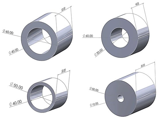
Figure 2. CAD model of a parametric solid consisting of a cylinder with a hole. The main parameters that help define the shape of the solid are the two diameters and the height of the cylinder. The four configurations in this figure are obtained automatically by changing the parameters within the features tree.
The same mechanism of dependencies and relationships established within a part between modelling functions can be extended by introducing the same connections between several parts within an assembly. In this way, the benefits of parametric modelling can be extended to models consisting of several components. The user can thus create different configurations of an assembly in which the same components are arranged in different configurations and positions by imposing mating constraints between the parts. Similarly, the user has the possibility of modelling dependent couplings between parts: the diameter of a hole, for example, could be linked to the diameter of the pin to be housed there. The result is a design that lends itself to dynamic modification without the need to intervene at each iteration of the original modelling functions.
To these ends, in [11], parametric design’s generative and evolutionary features are examined. The work suggests carrying out a thorough study to conceptualise designers’ problem-forwarding and solution-reflecting parametric design techniques. The solution-reflecting approach, which focuses on the designing solution space, can provide original solutions through parametric design. The efficient adoption of parametric design methods to better meet the demands of digital design and visualisation in many industrial sectors is supported by a deeper understanding of these techniques. In [12], by employing forms as parameters and conceptualising parametric design as a generic process, a set of design methods are utilised to improve the design capabilities of a parametric model to execute design variations. As a result, a parametric model develops into a versatile tool that facilitates modifications at the topological and geometrical levels.
All the results of analyses and verifications can be automatically incorporated into the technical report of the project, thanks to integrated management tools offered by the most complex CAD systems; all these tools allow the designer to carry out a series of preliminary verifications with as little effort as possible, increasing the value of the project and allowing a progressive transition from concept to finished product condition.
A further category of tools that seeks to offer design support, particularly useful for less experienced designers or those with limited technical expertise, is the set of tools for guided modelling of certain predefined components. An exemplary case in this regard is the modelling of connection elements such as screws, nuts, studs, and similar components. Since these are presented as standard elements in most cases, it is possible to refer to pre-modelled templates for the modelling phase. The user, in this case, is only required to enter the template code of interest, or the measurements they want to be respected, and the software autonomously introduces a solid with the required characteristics. The same principle can be extended to less common components or those with more complex geometry; in this case, the a priori definition of valid shapes that can be adapted to the designer’s needs may be more complex. A significant example could be the possibility offered by NX, a CAD system developed by Siemens (Siemens AG, Munich and Berlin, Germany), to insert anatomical shapes defined by reference measurements (e.g., hands, the basic structure of the human body, Figure 5) into the modelling environment. The introduction of these models can be particularly useful for the designer to develop human–machine interfaces and take care of the ergonomics of the project.
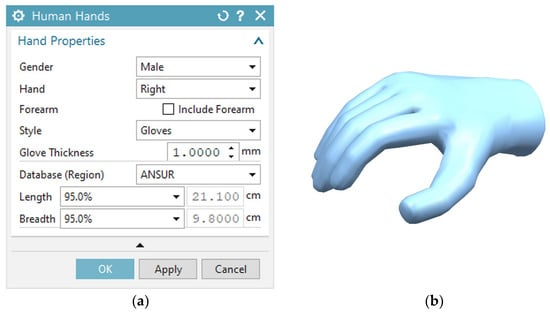
Figure 5. (a) Siemens NX command interface for modelling a human hand with certain user-selectable characteristics; (b) result of the modelling operation (https://plm.sw.siemens.com/it-IT/nx/cad-online/, accessed on 3 September 2023).
By taking advantage of the possibility offered by parametric CAD to call up the modelling tools offered by the programme’s graphical user interface in a programming environment, it is also possible to develop modelling tools customised to the designer’s needs. This effort is justifiable in the case of components that always have the same characteristics and shapes but with different dimensions each time.
Remaining in the more traditional field of mechanics, an example of this phase is the tool called ‘DuctWorks’ [15] which implements a CAD-based tool supporting and partly automating the complex structural ventilation system (VS) design process (see Figure 6).
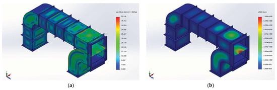
Figure 6. (a) CAD model of a duct with subdivision of the main duct into two secondary ducts. One of the two is characterised by a narrowing section. All connecting and reinforcing elements between the individual blocks are inserted automatically; (b) FEM analysis of the duct, performed automatically by the software for component verification.
The tool is specifically designed to perform a structural assessment of dynamically inserted ducts within a centrifugal compressor conditioning system, which is of the utmost importance given the considerable dimensions and stresses to which this type of VS is subjected in the specific field of the power generation industry. Thanks to all the functions and features described, parametric modelling presents itself as a technology preferentially oriented towards the world of industrial design and production.
2.2. The Role of Generative Design and Topological Optimisation in Aesthetic Design Education
The latest developments in methods and tools for aiding aesthetic design are related to the development and introduction of artificial intelligence algorithms into the design world [16]. SOLIDWORKS software maker Dassault Systemes Company (Vélizy-Villacoublay, France) is one of the top businesses that has used AI in its design product [17]. The company established xDesign, a technology that operators can use to deploy various solutions to their design difficulties instantly through cloud collaboration and that leverages AI to extrude and draw in engineering design projects. The operator starts by developing the model and specifying the restrictions. The part will then be instantly generated by SOLIDWORKS xDesign using AI that is integrated into its system depending on the limitations specified by the user [18]. Additionally, extended reality (i.e., virtual reality (VR), augmented reality (AR), and mixed reality (MR)) has been researched for AI in CAD. In such a setting, simulation outcomes occur in a 3D environment, enabling the viewing of things in three dimensions [19]. Thanks to the development of computing systems, the search for ever more efficient algorithms, and the emergence of remote computing systems (e.g., the ones working in the cloud), it is now possible to apply optimisation algorithms of several types to the study of structural problems. These tools, initially offered in independent software packages, have progressively been integrated within traditional CAD environments to ensure simplicity and speed in the use of tools in a synergetic manner.
Recently, a range of technological sectors have increasingly used generative approaches, i.e., Generative Design (GD), a specific kind of software and computer-aided design approach that leverages AI to speed up the design process. Using Generative Design tools, engineers may swiftly loop through several design options and select the best one based on a set of criteria [23]. Some functions that are typically completed by human designers, such as concept creation and product optimisation, can be delegated to the Generative Design tool in Generative Design. The way designers approach the design process may be drastically altered as a result. Designers may think about how to establish a system for design that would enable the design tool to generate a large number of legitimate outputs rather than how to create multiple one-off designs. Setting the necessary requirements, production techniques, and product architecture at an early stage of the process can help with this.
The knowledge the designer brings to each stage of the design process is arguably the most significant input into the Generative Design process. As they define and iterate on the objectives, parameters, and restrictions, choose among the results produced by the tool, and refine to create the final design, designers apply their design expertise, intuition, and understanding of the users and context to the design process. According to one designer, the Generative Design tool may be developed upon this designer’s experience as a base.
However, GD should be used in the design’s starting phase, giving engineers and aesthetic designers valuable feedback for initial design possibilities. Therefore, GD can see a much wider and more innovative design space, even for inexperienced designers. In fact, GD can be adopted when the shape of a product is not defined and there is a need to consider several different options. taking into consideration the desired material and manufacturing method. In particular, it can elaborate and provide a human user with several reasonable answers for a design challenge by utilising artificial intelligence capabilities. It is possible to use methods and tools that strive to maximise a target function given to the algorithm and fulfil a set of enforced design restrictions. The suggested alternatives are the outcome of an artificial intelligence-guided iterative search of the relevant solution space. These tools have recently seen a rise in popularity in the design community because of the considerable increase in computational power available. In the realm of architecture, GD has made some initial inroads [24] and has often been used in open-problem settings with huge design spaces. Practically speaking, GD tools just look for a mathematically defined solution to a problem; this frequently leads to an iterative optimisation process that aims to minimise an objective function. In light of this, GD has demonstrated its use in identifying unusual solutions that do not correspond to the usual set of forms or configurations employed.
This technology has recently been extended using the GD feature of Autodesk’s CAD Fusion 360® 2023 program. Later, Autodesk used this name as the commercial designation for an advanced proprietary version of a Topological Optimisation tool. Currently, the program only allows users to attack components that are subject to static caries. Figure 7 [24] shows the Generative Design framework.
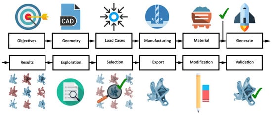
Figure 7. Autodesk Generative Design framework [24].
The Autodesk program uses the same workflow, but instead of offering the user a single solution, it suggests several viable alternatives that the project manager should consider. The program displays the alternatives together with the findings of the carried-out structural analysis. The developer can choose the most convenient method by fusing the data generated by the program with their own personal knowledge. The most practical solution could not be the one with the best mechanical characteristics for a variety of reasons, which the user is free to consider. Ergonomics, aesthetics, and producibility are some of the key design factors; however, they cannot easily be codified and understood by artificial intelligence. The project manager must evaluate how to include these aspects considering the model’s structural performance using such a strategy.
This makes it possible to utilise the benefits of both approaches. Due to the opportunity it provides to explore unique and unusual forms, this technology has found widespread use in the field of design. Figure 8 shows an example [24].
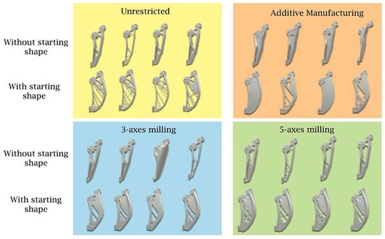
Figure 8. Shapes produced by Autodesk Fusion 360 using the Generative Design tool. The piece is a robotic arm for lifting rock material, created by imposing construction constraints relevant to various technologies (3- and 5-axis milling, Additive Manufacturing, without manufacturing constraints).
2.3. The Role of Additive Manufacturing in Aesthetic Design Education
The role of additive technologies (ATs) in the prototyping issue of design is extensively discussed in [26], which explores the literature contributions focused on the different perspectives of prototyping activities for design purposes, searching for both available knowledge and research needs concerning the correct exploitation of ATs. One of the main findings of such a work is that regarding the influence of AT-based prototyping on design results: the CAD modelling of the solution to be physically prototyped is the factor that has the most influence on designers’ cognitive processes. A further intriguing research idea arises as a direct result of the potential cognitive constraints brought on by the required CAD: looking into the feasibility of developing a CAD software and/or hardware ad hoc for Rapid Prototyping in the context of designing, capable of somehow promoting positive cognitive activities of designers, and subsequently allowing to fruitfully exploit manufacturing to enhance creativity of design outcomes. The primary application of this issue, therefore, is the prospective availability of CAD platforms (or plugins) for Rapid Prototyping to better encourage creativity in the initial design stages.
Moving from the product’s conceptual design—where, as previously mentioned, context, target, innovation (both in terms of form and functionality), alternative materials, and style are prioritised—to the actual project for production ushers in a challenging stage in which the project manager is required to work on a continuous revision of the various developed concepts in order to support the operational phase of the product. The ability of the product designer to modify their own product concept to the specifications of its manufacturing is crucial [27]. As a result, it is important to understand the possibilities and limitations of the technical approach being used. In this executive phase, it should come as no surprise that the designer frequently collaborates with mechanical engineers and technologists who can assess, set up, and validate all conventional mechanical processes, including foundry forming processes, deformation processes (rolling, forging, extrusion, and sheet metal machining), subtractive chip removal processes (milling, turning, and grinding), and joining processes (welding, brazing, and bonding).
The use of these technologies almost always imposes restrictions on the topology and geometry of the products to be made, even though they are not necessarily conventional [28]. These restrictions are represented in the product design through a number of decisions and compromises that inevitably cause the concept and the result to diverge dramatically. The usage of additive technologies, often known as 3D printing or fast prototyping methods, has undergone a dizzying expansion and subsequent proliferation in both commercial and academic settings over the past three decades to provide the designer with more freedom. In contrast to traditional machine tools (lathes, mills, and drills), which remove parts of existing material to produce finished goods (subtractive manufacturing), 3D printing builds objects by adding material, allowing the creation of finished products or parts of them. The operating theory relies on the idea that everything is made up of several parts, each of microscopic thickness. Thus, the challenge is reduced from three dimensions to two dimensions and the quick prototype is built section by section.
However, over time, its use has come to be increasingly considered as a substitute for the actual final production of things (or sections thereof) that are challenging to make using conventional subtractive processes. Additive Manufacturing was initially employed for the fabrication of prototypes. The number of contributions per year that list “Additive Manufacturing” (or “additive manufacturing”) among their keywords—10 in 2006 versus more than 1100 in 2020 (database: Scopus, 2022)—evidences the recent significant rise in interest in research on topics related to 3D printing. These contributions include a wide range of research topics, such as materials, software, device technical progress, and effects on design methodologies.
3. Conclusions
Through the gradual adoption of inclusive, dynamic, and collaborative design principles that consider the various aspects of product manufacturing, contemporary aesthetic designers are faced with the task of expanding their knowledge and skills. This process entails going beyond traditional boundaries and embracing an interdisciplinary approach that considers the manufacturing elements inherent in the envisioned product. Fortunately, a wide range of software tools and technologies are now available to satisfy the demands of designers, ensuring seamless workflow, enhanced productivity, and unparalleled creativity for individuals of all skill levels. Examples of this include parametric CADs, which force the designer to pay close attention to factors of manufacturability from the very beginning of product creation. These advanced computer-aided design tools allow precise adjustments and real-time simulations, ensuring cost-effective production and high-quality end products. With the aid of these tools, users can effectively execute intricate dimensional control tasks, validate the compatibility of multi-component assemblies, evaluate mechanical and thermal resistance, and conduct Topological Optimisation, all in a cohesive manner. There are also many 3D printing methods accessible today, to be employed both in the conceptual phase (prototyping) and for real manufacturing, especially when it is necessary to make complicated forms when cost-effective.
This entry is adapted from the peer-reviewed paper 10.3390/designs7060127
This entry is offline, you can click here to edit this entry!