Your browser does not fully support modern features. Please upgrade for a smoother experience.
Please note this is an old version of this entry, which may differ significantly from the current revision.
Subjects:
Computer Science, Software Engineering
Interconnected data or, in particular, graph structures are a valuable source of information. Gaining insights and knowledge from graph structures is applied throughout a wide range of application areas, for which efficient tools are desired.
- graph analysis
- framework
- transformation
- verification
1. Introduction
In recent years, the significance of network analysis and graph structures has grown substantially in both academia and industry. This is because they offer the capability to represent and analyze massive amounts of interconnected data. In this way, it is possible to gain valuable insights across a broad spectrum in the area of application domains, including but not limited to planning, vulnerability analysis, social networks, modeling, and also gene expression, protein interactions, Web graph structure, Internet traffic analysis, and disease spread through contact networks [1,2,3,4,5,6,7]. For example, Jo et al. [8] used graph representations for the visualization of online bibliographic datasets, together with an interactive interface for performing visual exploration of the information network, to get an in-depth analysis of, for example, understanding the history and flow of research, its current status, and ongoing trends. Ureña et al. [9] proposed a completely different use-case for utilizing graphs allowing to model the relationships and the history of reputations such as likes of social media users as a source of trustworthiness. The growth of network theory is driven by its cross-disciplinary significance and it serves as a crucial tool in a systematic method of understanding complex systems. To meet the growing demand for efficient graph analysis tools, several libraries have been proposed that offer a comprehensive and user-friendly approach for defining, representing, and analyzing graph structures [10,11,12,13].
Creating a strong, efficient, and versatile graph library is a challenging process with numerous design decisions and performance compromises. While existing libraries primarily focus on the representation and analysis of graph structures, the researchers introduce the Graph Transformation Framework (GTF), an open-source Java library that offers the means to separate graph representation and analysis. The researcher's study outlines the design of GTF, discussing key considerations and showcasing its key features and supported algorithms. GTF provides a simple Java-based API to define and represent a graph, and also includes a mechanism to transform the graph structure to an arbitrary output format, allowing for subsequent analysis and verifying its consistency. This makes GTF suitable for scenarios where an input network structure needs to be transformed into a desired target structure.
2. The Graph Transformation Framework
In the following parts present the Graph Transformation Framework [27] and describe its basic features, which include an API for (1) the definition of graph structures, (2) the specification of rules to transform a graph structure to a desired output format, and (3) the definition of constraints to ensure consistency in relation to a graph transformation. These modules and their interaction are shown in Figure 1.
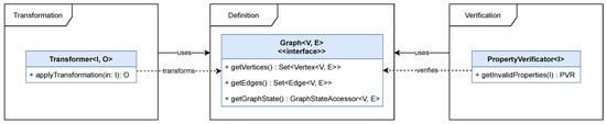
Figure 1. High level overview showing the interaction of the main modules for Graph Definition, Transformation, and Verification based on the corresponding classes.
2.1. Graph Definition
In this work, the researchers rely on a basic graph definition, where a graph G consists of a set of vertices V and a set of edges E, which allows for defining a graph as 𝐺=(𝑉,𝐸). In addition, an edge consists of a source and a target vertex, which allows for deriving the two functions 𝑠,𝑡:𝐸→𝑉 from it. This formal graph definition builds the foundation for a set of core interfaces defined in GTF and shown in Figure 2. The researchers differentiate between three concepts:  The graph, with vertices, edges and its traversal strategy, shown in blue.
  A graph state, which holds the internal state, shown in green.
  A builder concept, to create a new graph, shown in yellow.
The graph, with vertices, edges and its traversal strategy, shown in blue. A graph state, which holds the internal state, shown in green. A builder concept, to create a new graph, shown in yellow.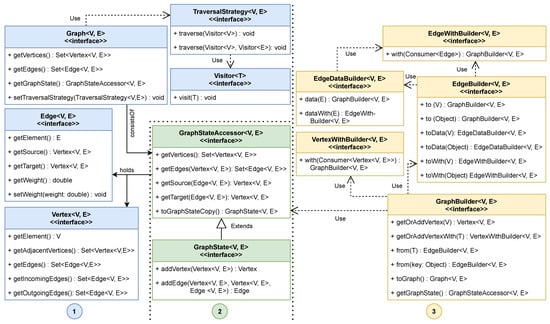
Figure 2. The core interfaces of the GTF with Graph as a central component, consisting of a GraphStateAccessor, which is responsible for a graph’s components with Edge and Vertex objects. While the accessor represents a read-only view of the graph, it is extended by the write-able variant GraphState. Next to the actual graph-related domain interfaces, GTF provides multiple builder concepts to create a graph from scratch using given objects, which should be decorated.
The most central component is the generic Graph interface. This interface is used to represent a graph-based object structure. Furthermore, a Graph provides the required means to interact with its components, the vertices, and edges. To access and manage these components a GraphStateAccessor was used, which represents a read-only view of the state of a graph. Depending on the implementation, this state is either represented as an adjacency matrix or any other means to efficiently store vertices and associated edges. In the context of the GraphStateAccessor, there is another extension of this interface called GraphState, which not only allows to read the vertices and edges of a graph, but also gives the possibility of manipulating the graph by adding or removing parts. Every vertex and edge in the GTF is used as a container and is decorated by another element. These elements contain the actual information of the graph.
interface. This interface is used to represent a graph-based object structure. Furthermore, a Graph provides the required means to interact with its components, the vertices, and edges. To access and manage these components a GraphStateAccessor was used, which represents a read-only view of the state of a graph. Depending on the implementation, this state is either represented as an adjacency matrix or any other means to efficiently store vertices and associated edges. In the context of the GraphStateAccessor, there is another extension of this interface called GraphState, which not only allows to read the vertices and edges of a graph, but also gives the possibility of manipulating the graph by adding or removing parts. Every vertex and edge in the GTF is used as a container and is decorated by another element. These elements contain the actual information of the graph.Since the basic GraphStateAccessor represents a read-only view of the graph, GTF provides a builder pattern API to create the graph, but is not limited to this way of creation. For this reason, the GraphBuilder interface allows creating vertices and edges via method chaining with “addVertex”, “from”, and “to” definitions that are delegated to specialized vertex and edge builders called VertexWithBuilder and EdgeBuilder.
to create the graph, but is not limited to this way of creation. For this reason, the GraphBuilder interface allows creating vertices and edges via method chaining with “addVertex”, “from”, and “to” definitions that are delegated to specialized vertex and edge builders called VertexWithBuilder and EdgeBuilder.Based on these concepts, it was able to create a weighted, directed graph structure. The structure also supports creating self-referencing vertices. Multiple edges between two nodes are not yet supported. All these limitations are given for the current implementation, and based on the concept it is possible to implement other Builders and GraphStates that allow for different graphs to be represented. The example shown in Listing 1 shows how the API can be used to create a graph representation. In this example, a graph of persons is built, with relations between them.
2.2. Graph Transformation
Once a graph instance is defined, the framework provides an API to transform the input graph into a desired output. The format or type of the output, however, is not predetermined. To achieve this, GTF introduces two fundamental concepts; a Transformer and a Renderer, which are depicted in Figure 3.
| Listing 1. Example of how a graph can be generated using the methods from the GTF. |
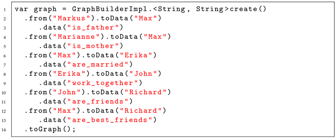 |
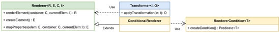
Figure 3. The base transformation classes, consisting of a Transformer, which is responsible for base level transformation, and a TransformationRenderer, which renders single elements in the transformation process. Additionally, a ConditionalRenderer and its RendererCondition is shown, which is used to process different elements in the transformation.
2.2.1. Transformer
Specifying a transformation from a source graph structure requires defining transformation rules. The researchers define that as a function t which transforms a graph G into a target model T, expressed in 𝑡:𝐺(𝑉,𝐸)→𝑇. One thing that has to be highlighted here is that the target model can be of any structure and does not need to be a graph again. Like this, it is possible to transform the graph, for example, to a textual representation. In GTF, such transformation rules are combined using a Transformer. GTF provides several Transformers out of the box, e.g., the GraphVizTransformer which enables transformations from a GTF defined graph structure to the .dot-format. The Transformer is further responsible to traverse the source graph structure and apply the available transformation rules on a per-element basis.
2.2.2. Renderer
For each single element traversed, a Renderer is used to transform it from its source representation to the desired target representation. Henceforth, a Renderer is responsible for rendering a single element as part of the whole transformation process. Given a graph structure as the source input for the transformation process, a Renderer is responsible to transform a single Vertex or Edge from that particular graph instance. A Transfomer usually contains a series of Renderer implementations which provide three consecutive steps that are executed during the transformation. First, a Renderer is responsible for creating the desired target element representation of the current source element it is being applied to. This is achieved using the createElement method depicted in Figure 3. Second, the values and the desired properties are mapped from the source element to the target element using the mapProperties method. Finally, the renderElement method combines those two together and creates the final result. To allow for processing of different types of source elements, a special renderer the ConditionalRenderer qA introduced, which decides based on a condition using RendererCondition instances if a specific element should be processed by a particular Renderer or not.
2.2.3. Illustrative Example
Given the provided abstract description of the two fundamental concepts for transforming a graph structure, the researchers further provided an illustrative example that shows the interplay between the described components and further shed light on how the transformation is applied. The example shows how the graph structure defined in Listing 1 is transformed to a GraphViz representation for visualization. The initial step is to create a transformer, and Algorithm 1 shows the individual steps.
| Algorithm 1: Specifying a Transformer for a graph to GraphViz transformation. |
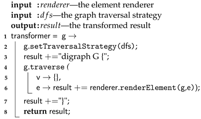 |
A Transformer requires a traversal strategy for processing the underlying source graph structure. Furthermore, creating a Transformer requires specifying which elements of the graph should be traversed. GTF allows both—a transformer which operates on vertices or on edges. For the transformer in Algorithm 1 the researchers only defined an edge-based traversal which allows for an efficient transformation into valid GraphViz .dot-file statements. The responsibility for the actual transformation of an edge to the desired target element, however, lies within a Renderer. Algorithm 2 shows the implementation of the mapProperties method, which maps an edge from a traversed graph to its string representation in the GraphViz .dot-file format.
| Algorithm 2: Mapping properties from source to target element for simple graph to GraphViz transformation. |
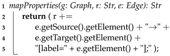 |
For the case at hand, the mapping is a simple graph to text transformation. However, advanced transformation scenarios, e.g., graph to model transformations, are also possible. Once the Transformer and the Renderer are defined, graph instances, e.g., the sample graph from Listing 1, can be transformed to a GraphViz representation which results in the rendered graph visualization in Figure 4.
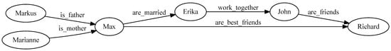
Figure 4. The rendered GraphViz representation that was created with Algorithms 1 and 2 from the graph created in Listing 1. Rendered with https://dreampuf.github.io/GraphvizOnline (accessed on 3 April 2023).
2.3. Graph Verification
A crucial part in the GTF when transforming a source graph into a target representation is to ensure that the input source satisfies all requirements to ensure the validity of the resulting target output. Therefore, in the GTF, the researchers provide a mechanism to verify if a source input graph is syntactically sound according to given constraints [28]. The researchers define a constraint r that takes any input I and results in a boolean result, expressed as 𝑟:𝐼→𝑏𝑜𝑜𝑙𝑒𝑎𝑛. The verification v takes a set of these constraints 𝑟𝑠 and individually applies them with the given input I, expressed as 𝑣(𝑟𝑠,𝐼):∀𝑟∈𝑟𝑠→𝑟(𝐼). This verification process is loosened from the actual graph structure used in GTF to contribute a generally usable method, as shown in Figure 5. To achieve this, a PropertyVerificator was used which returns invalid properties in the form of a PropertyVerificatorResult for a given object and its referenced child objects. Invalid properties are defined via constraints, which are managed by a PropertyRestrictor object on either a class or field level. The traversal of the underlying graph was done via a visitor pattern based on the AbstractVisitor class, which is extended by different implementations which are built in descending order from object down to field and primitive class level. Likewise, an object is disassembled by its components and every part is visited and checked by the verification mechanism. The different visitor implementations are managed by a ConstraintVisitorFactory class.
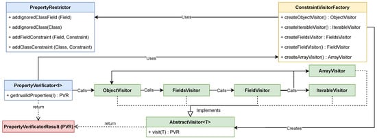
Figure 5. The syntactic verification process of the GTF is based on the PropertyVerificator that results in a PropertyVerificatorResult and uses an ObjectVisitor to check given constraints defined in the PropertyRestrictor class. An ObjectVisitor, in turn, uses a FieldsVisitor to check its fields, where every individual field is again checked by a Fieldvisitor. Depending on the type of the field, this visitor checks the defined constraints or repeats the process via a ObjectVisitor, ArrayVisitor, or IterableVisitor for the referenced child objects.
This entry is adapted from the peer-reviewed paper 10.3390/software2020010
This entry is offline, you can click here to edit this entry!