歯科矯正用アンカースクリュー (OAS) の最適な挿入トルク (IT) は、OAS の特徴と挿入方法によって異なるという仮説が立てられました。IT と成功率は、上部頬側歯槽領域と下部頬側歯槽領域でそれぞれ 6.0 ± 3.2 ~ 15.7 ± 2.3 Ncm、62.5 ~ 100.0% の範囲でした。口蓋中央部の範囲は、それぞれ 14.5 ± 1.6 ~ 25.6 ± 5.5 Ncm および 83.0 ~ 100.0% でした。一般的に使用される φ1.5 ~ 1.7 mm の OAS では、上部歯間領域と下部歯間領域でそれぞれ 5 ~ 12 および 6 ~ 14 Ncm の IT が最適であることがわかりました。口蓋中央縫合領域では、テーパー付き φ1.5 mm および φ2.0 mm OAS には、それぞれ 11 ~ 16 Ncm および 20 ~ 25 Ncm の IT が適していると考えられました。特定された最適な IT 範囲は推奨に値しますが、配置中は常に IT を監視するように注意する必要があります。
1. はじめに
さまざまな動きに使用される歯科矯正用固定ネジ (OAS) は、使いやすく信頼性があります。OAS は、前歯の一括後退と歯列弓の遠位化のため、上顎と下顎の頬側歯間領域、および口蓋中央領域の絶対固定装置として頻繁に使用されます。したがって、OAS の安定性に関する情報は、歯科矯正治療の成功にとって非常に重要です。
挿入トルク (IT)は、 OASの安定性に影響を
与える要因の 1 つと考えられています [
1、2、3 ]。
歯列矯正で使用されるネジは、一般
に直径 1.0 ~ 2.3 mm、長さ 3 ~ 15 mm です [ 4、5、6
]。本吉ら。[
7 ] は φ1.6 × 8 mm OAS を調査し、最適な IT は 5 ~ 10 Ncm であると推奨しており、この範囲は多くの臨床医や研究者によって採用されています。ただし、文献にはバリエーションがあります。以前の研究ではテーパー付きセルフタッピング φ2.0 × 6 mm OAS が使用され、IT が 25.6 ± 5.5 Ncm と報告されました [
8 ] が、別の研究では上顎に円筒形セルフドリリング φ1.5 × 7 mm OAS が使用されました。頬歯槽領域であり、ITs は 6.0 ± 3.2 Ncm と報告されています [
9 ]。したがって、IT 値は、配置方法と OAS の設計 (ネジの直径、長さ、テーパー形状または円筒形状) によって大きく異なります [
1、
5、
6、
7、
8、
9、
10、
11、
12、
13、
14、
15 ]。したがって、臨床医はこれらの値を実際に適用することを躊躇する可能性があります。
たとえば、口蓋中央領域には隣接歯間領域の骨よりも厚い皮質骨が含まれているため、より高い IT の方が適している可能性があります。さらに、OAS の IT は、OAS の設計や挿入技術によって異なる場合があります。
2. 歯科矯正用アンカースクリューの配置に最適な挿入トルク
2.1. Placement Methods (Self-Drilling or Self-Tapping)
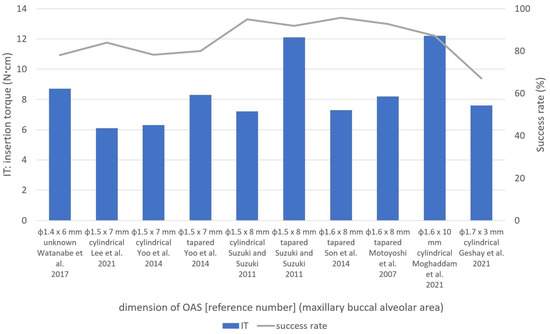
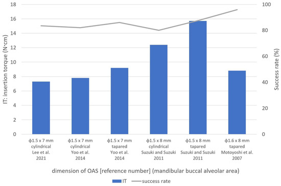
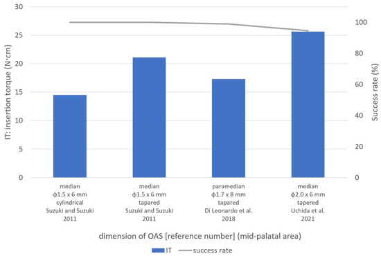
ITs and success rates of OASs placed in the buccal alveolar and mid-palatal areas are listed in
Figure 2,
Figure 3 and
Figure 4. However, data from one study [
10] were not included because the data for φ1.3 mm and φ1.5 mm OASs in the buccal alveolar area were unified, and separate values were not available.
Figure 2. Insertion torques (ITs) and success rates according to OAS features in the maxillary buccal alveolar area. Explanations for each bar graph in the figure were listed in the following order: screw dimensions, screw form, authors, and published year [
1,
6,
7,
9,
11,
13,
14,
15].
Figure 3. Insertion torques (ITs) and success rates according to OAS features in the mandibular buccal alveolar area. Explanations for each bar graph in the figure were listed in the following order: screw dimensions, screw form, authors, and published year [
7,
9,
13,
15].
Figure 4. Insertion torques (ITs) and success rates according to OAS features in the mid-palatal area. Explanations for each bar graph in the figure were listed in the following order: screw dimensions, screw form, authors, and published year [
8,
12,
15].
In self-drilling OASs, the ITs ranged from 6.0 ± 3.2 Ncm [
9] to 21.1 ± 2.2 Ncm [
15], while the success rates ranged from 64.3% [
6] to 100.0% [
10,
15]. Thinner, cylindrical, φ1.5 mm OASs had the lowest ITs [
9], whereas the highest ITs were in the mid-palatal area [
15]. Thus, IT in self-drilling OASs was affected not only by OAS diameter but also by the placement site. Short 3.0 mm OASs had the lowest success rates [
6]. Therefore, short, self-drilling OASs were found to increase the risk of failure.
Regarding self-tapping OASs, Motoyoshi et al. [
7] used tapered φ1.6 × 8.0 mm OASs in the upper and lower buccal alveolar areas. In their study, OASs with a 1.0 mm pilot hole in maxilla (diameter ratio: bone drilling diameter/screw diameter × 100 [%] = 62.5%) and a 1.3 or 1.4 mm pilot hole in the mandible (diameter ratio = 81.3–87.5%) showed ITs and success rates of 7.6–8.9 Ncm and 91.8–95.0% in the maxilla and 8.5–8.8 Ncm and 91.9–100.0% in the mandible, respectively (except for the early-loading adolescent group) [
7]. They also stated that the pilot-hole diameter in the mandible was extended from 1.3 mm to 1.4 mm when IT exceeded 10 Ncm depending on bone stiffness or cortical bone thickness. ITs and pilot-hole diameters are likely to affect the success rates in self-tapping OASs [
7].
In the mid-palatal area, tapered φ2.0 × 6 mm OASs placed into 1.2 mm (diameter ratio = 60.0%) and 1.5 mm pilot holes (diameter ratio = 75.0%) had success rates of 94.5% (IT = 25.6 ± 5.5 Ncm) and 83.0% (IT not available), respectively, with a significant difference [
8]. Therefore, it is suggested that the IT should be controlled, using different pilot-hole diameters in different placement sites with varying cortical bone thickness, to prevent bone and OAS fracture.
This contradiction between the results of two studies [
14,
15] may be explained by the differences in OAS characteristics. One important difference was the diameter ratio for self-tapping OASs (62.5% in the Son et al. [
14] study). The tightness for tapered OASs could increase the IT and may be considered equivalent to the ITs observed in self-drilling OASs. Another study by Suzuki and Suzuki [
15] used a diameter ratio of 75.0% in self-tapping OASs [
15]. Under such conditions, the diameter ratio may cause lower ITs that are not equivalent to the ITs of self-drilling OASs. Another difference was the shape of the OASs. Suzuki and Suzuki [
15] used cylindrical self-tapping OASs in contrast to the tapered screws in the Son et al. study [
14].
As a result, no significant differences in ITs and success rates were recognized between the self-drilling and self-tapping OASs if the same OAS shape was used. However, an in vitro study using the synthetic bone blocks by Tepedino et al. evaluated the relationship between insertion torque and stability of the self-tapping and the self-drilling OASs and concluded that the self-drilling OASs showed a higher maximum IT than the self-tapping OASs under the same conditions of bone-like support and same inner diameter [
2].
2.2. Shapes and Dimensions of OASs
2.2.1. Tapered and Cylindrical OASs
ユら。[
13 ] は、テーパー型と円筒型のセルフドリリング φ1.5 × 7 mm OAS を比較し、上顎頬側歯槽領域において円筒型 OAS (6.3 ± 2.8 Ncm) よりもテーパー型 OAS (8.3 ± 3.7 Ncm) の方が有意に高い IT を報告しました。彼らは成功率に有意差はないと報告した [
13 ]。
スズキとスズキ [
15 ] は、同じ寸法(頬側歯槽領域では φ1.5 × 8 mm、口蓋中央部では φ1.5 × 6 mm)のテーパー型(セルフドリリング)および円筒型(セルフタッピング)OAS を使用しました。縫合部)、テーパ状 OAS の IT が円筒形 OAS(7.2 ± 1.4 Ncm、12.4 ± 1.2 Ncm、14.5 ± 1.6 Ncm)よりも高いことがわかりました(それぞれ 12.1 ± 3.1 Ncm、15.7 ± 2.3 Ncm、21.1 ± 2.2 Ncm)。 ) すべてのサイトにあります [
15 ]。
in vitro 研究で、Assad-Loss らは、[
16 ] は、いくつかの OAS 設計 (φ1.5 ~ 1.6 × 6 ~ 7 mm) の破壊トルクを評価し、結果に最も影響を与える特性は内径と外径の比であると報告しました。クーニャら。[
17 ] は、低密度および高密度の牛骨を使用してテーパー型と円筒型の φ1.6 × 8 mm OAS の IT を比較し、高密度骨ではテーパー型 OAS の方が円筒型 OAS より IT が高いと報告しましたが、低密度骨 [
17 ]。
2.2.2. OASの寸法
Chenらによるin vitro研究。[ 21 ] は、密度 20、30、および 40 pcf の人工骨を使用した φ1.3 × 7 mm OAS (セルフドリリング) の機械的特性を調査し、それぞれ 3.9、5.2、および 10.0 Ncm の IT を報告しました。
ある研究で口蓋中央縫合領域に使用された大型のφ2.0 × 6 mm OAS は、94.5% の成功率と最高の IT (25.6 ± 5.5 Ncm) を示しました [8] (図4 )。Nienkemper らによる in vitro 研究。[ 23 ] はブタの骨盤を使用して φ2.0 × 9 mm OAS を評価し、挿入深さ 4 mm、5 mm、および 6 mm の IT が 15.4 ± 7.0 Ncm、26.2 ± 10.4 Ncm、および 27.2 ± 14.1 Ncm であると報告しました。それぞれ。これらの結果 [ 23 ] を考慮すると、φ2.0 × 6 mm OAS の高い IT [ 8 ] は、口蓋中央縫合部などの高密度骨領域に適している可能性があります。
2.3. 設置場所
2.3.1. 頬歯槽領域
これらの研究に基づいて、この領域ではφ1.5〜1.7 mmのOASが一般的に使用され、上部および下部頬歯槽領域の円筒形OASにはそれぞれ5〜8 Ncmおよび6〜12 NcmのITが最適でした。テーパー付き OAS の場合、IT は 6 ~ 12 Ncm および 8 ~ 15 Ncm が最適です。
2.3.2. 口蓋中央部
口蓋中央領域への OAS の配置は、前歯の後退や上顎弓における臼歯の侵入、遠位化、突出など、さまざまな目的に使用されます [28
]。この領域への OAS の配置は、解剖学的にも隣接歯間領域よりも好ましいと考えられています [
29 ]。ただし、Naya-Imaiらによって報告されているように。[
30 ]、成人でも縫合糸の閉鎖が不完全である可能性があるため、OAS 留置前にコーンビーム CT などの適切な画像診断を使用して口蓋正中縫合糸の縫合深さを考慮する必要があります。この点に関して、彼らは、未縫合領域への挿入を防ぐために、口蓋中央縫合糸での OAS の留置は年齢に関係なく避けるべきであると結論付けました。
口蓋中央領域は、特に正中縫合糸に近い皮質が厚いため、IT 制御のために OAS を配置する前に事前のドリリングが必要になることがよくあります
[ 8、15
]。スズキおよびスズキ [
15 ] は、この領域で円筒形とテーパ状の OAS (φ1.5 mm) の両方を使用し、前者の方が IT が低いと報告しました。円筒形 OAS の IT と成功率は、それぞれ 14.5 ± 1.6 Ncm と 100.0% でした。
in vitro 研究では、Wilmes et al. [
26 ] は、φ1.5 mm およびφ2.0 mm OAS の破断時の最大トルクがそれぞれ 20.1 ± 3.8 Ncm および 49.2 ± 7.5 Ncm であると報告しています。Dalla Rosaらによるin vitro研究では、[
27 ]、φ1.5 mm OAS の破壊までの降伏トルクは 16.3 ± 1.6 Ncm でした。
これらの研究に基づいて、スズキおよびスズキ [ 15 ]によって報告されたφ1.5 mm OAS の IT 21.1 ± 2.2 Ncm は降伏トルクを超えました。したがって、口蓋中央縫合部には、IT が 20 ~ 25 Ncm の φ2.0 mm テーパー OAS の使用が適していると考えられます。
2.3.3. 頬骨下縁と頬側棚領域
頬骨下稜および頬側棚領域には、歯槽隣接面領域に比べていくつかの臨床的利点がある[ 33、34
]が、これらの部位のOASを調査した研究はほとんどない
。スリーニバサガンら。[
3 ] これらの領域の OAS (φ2.0 × 12 mm) の IT を調査したところ、頬骨下縁 (ネジ 12 本) および頬棚 (ネジ 4 本) 領域での IT と成功率は 10.1 Ncm および 83.3% であることがわかりました。それぞれ10.3Ncmと100.0%。これらの領域では約 10 Ncm IT が最適であると考えられていますが、これらの配置場所を調査するにはさらなる研究が必要です。
3. 結論
IT と成功率は、上部頬側歯槽領域と下部頬側歯槽領域でそれぞれ 6.0 ± 3.2 Ncm ~ 15.7 ± 2.3 Ncm、62.5% ~ 100.0% の範囲でした。口蓋中央領域の場合、範囲はそれぞれ 14.5 ± 1.6 Ncm ~ 25.6 ± 5.5 Ncm および 83.0% ~ 100.0% でした。一般的に使用されるφ1.5~1.7 mmのOASでは、上部歯間領域と下部歯間領域でそれぞれ5~12 Ncmと6~14 NcmのITが最適であることがわかりました。口蓋中央縫合領域では、テーパー付き φ1.5 mm および φ2.0 mm OAS には、それぞれ 11 ~ 16 Ncm および 20 ~ 25 Ncm の IT が適切であると考えられました。
This entry is adapted from the peer-reviewed paper 10.3390/app131910681