Your browser does not fully support modern features. Please upgrade for a smoother experience.
Please note this is an old version of this entry, which may differ significantly from the current revision.
Subjects:
Engineering, Mechanical
The ability to manufacture parts with complex geometry by sending a model from CAD directly to the manufacturing machine has attracted much attention in the industry, driving the development of additive manufacturing technology. However, studies have shown that components manufactured using additive manufacturing technology have several problems, namely high tensile residual stresses, cracks, and voids, which are known to have a major impact on material performance (in service).
- laser shock peening
- powder bed fusion
- fatigue
- residual stress
1. Introduction
According to the International Organization for Standardization/American Society for Testing and Materials in ISO/ASTM 52900:21, additive manufacturing is defined as “a process for joining materials to create physical objects specified by 3D model data” [1]. Unlike conventional manufacturing methods, which are subtractive, additive manufacturing sends data from CAD to the machine, and the part is made layer by layer until it is finished.
Recently, additive manufacturing technology is gaining momentum in various industries, such as aerospace [2,3], automotive [4], biomedical [5,6], and marine [7]. According to a report by Grand View Research, the global market for metal 3D printing is estimated at USD 656.5 million, with nearly 50% of this technology in the aerospace and defense industry, as shown in Figure 1, which was plotted using data collected from the report [8]. In another report by the same institute, the market for AM technology is expected to reach USD 76.16 billion by 2030 [9].
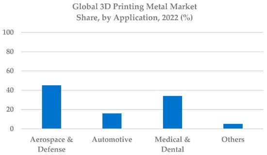
Figure 1. Market share of additive manufacturing in several industries.
There are many reasons for the increasing use of AM technology, for example, its ability to produce components with complex geometry in a single step, which is very difficult and sometimes impossible with conventional manufacturing technologies. Another major advantage of AM is that components are built layer by layer, which allows for more efficient use of materials because no material is wasted. In addition, AM methods can produce lighter components, which is highly valued in the aerospace industry, where a combination of safety and weight is important. Many other reasons contribute to the exploration of AM technology. The fact that a model is sent directly from CAD to the AM machine to produce a part helps save a lot of time by eliminating intermediate steps normally involved in conventional manufacturing, thus reducing time to market.
Many AM techniques have been developed, but they are all based on the same basic principle: a component is built up layer by layer until the component is complete. According to ASTM [1], additive manufacturing processes are divided into the following categories: material jetting, VAT polymerization, binder jetting, powder bed fusion, sheet lamination, and directed energy deposition, as shown in Figure 2.
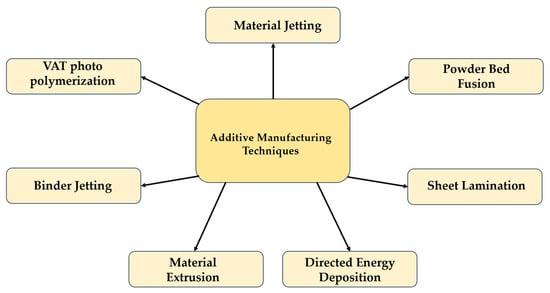
Figure 2. Additive manufacturing techniques.
In the early stages of AM technology development, the focus was on paper laminates, waxes, and polymers, but in subsequent years, the scope expanded to include other types of materials such as metals, composites, and ceramics. The AM techniques shown in Figure 2 can process all of these materials, but there are specific techniques that are best suited for each type of material. For example, for metallic materials, PBF, sheet lamination, binder jetting, and directed energy deposition are best suited, which is referred to as metallic additive manufacturing (MAM). In practical engineering applications, ensuring the reliability and safe operation of additively manufactured components is important, particularly for components that include notch features since the areas of geometrical discontinuities are recognized as stress concentration points. To ensure the integrity of AM-built components, Niu et al. [10] proposed a defect-tolerant approach that considers size effect, notch effect, and fatigue scatter. One great advantage of the proposed approach is the ability to estimate the AM part allowable defect size, and it has been shown that the size effect influences the lifetime of components [11].
Although the use of AM technology offers great advantages over conventional manufacturing processes, parts produced with AM processes still have shortcomings, such as surface defects, void formation, undesirable residual stresses, and anisotropic microstructure. All of these problems are known to negatively impact part strength and shorten part life. To counteract the problems associated with AM, several researchers have conducted several studies. For example, Gong et al. [12] studied the SLM samples of Ti6Al4V intentionally fabricated with defects by changing the manufacturer’s standard parameters to find an explanation for the defect formation. Based on the porosity results, a process window was created with four zones: “completely dense” (zone I), “overmelting” (zone II), “incomplete melting” (zone III), and “overheating” (zone OH) to show how the process parameters affect defect formation. Among these zones, it has been shown that only Zone I samples, which are free of porosity, can be produced with specific parameters that must be tuned to the material [13]. According to Li et al. [14], there are more than 100 parameters in the literature that affect the performance of an additively manufactured material. For this reason, it is not possible to solve the AM problems only by an optimization process.
To extend the lifetime of components manufactured with AM techniques, numerous surface post-treatment techniques have been developed, namely heat treatment (HT), hot isostatic pressing (HIP), nanocrystalline surface modification with ultrasound (UNSM), shot peening (SP), and LSP. Among the post-treatment methods, heat treatment is used to reduce the residual stresses generated in AM processes due to the high thermal gradient and rapid cooling rate. HIP has been successfully used to reduce porosity in IN718 [15,16], and the reduction in porosity resulted in an increase in lifetime. While the authors [17] found in one study that treatment with HIP alone improved fatigue strength by more than 100% compared to printed and stress-relieved specimens, in another study, better fatigue performance was achieved by stress relief rather than a combination of SR and HIP [18]. The authors concluded that the reduction in fatigue life was due to the presence of surface defects during HIP and that the complete elimination of pores was not achieved even at pressures greater than 100 MPa. Studies conducted with other post-processing methods such as UNSM [19], SP [20,21], and LSP [22] have shown that they were able to improve fatigue life by introducing CRS as well as by creating grain refinement.
Among all these surface post-treatment methods, LSP is currently considered one of the most efficient post-treatment technologies for improving the mechanical properties of the materials. Several advantages are associated with LSP technology. For example, Plessis et al. [23] applied the LSP technique to AlSi10Mg prepared by laser powder bed fusion (LPBF). The results showed that the LSP technique is able to close surface pores. It is known that areas with pores usually act as crack initiators, so LSP increases the fatigue strength of the material. Compared to SP, LSP treatment results in CRS with higher stability because it causes less cold deformation. Moreover, the LSP method achieves greater CRS depth [24]. In addition, LSP treatment allows the application of shock peening to components with different geometries as well as in certain areas of complex geometries that cannot be achieved with other surface treatments, which increases component lifetime. Since the CRS produced by LSP depends on the LSP parameters, they can be modified to produce a desired compressive residual stress field and avoid tensile stresses at critical locations.
2. PBF Working Principle
Powder Bed Fusion is known as the first commercially available AM technology; it is also the most widely used AM process for metallic materials. The operating principle of PBF is shown in Figure 1. The process takes place in a 3D printer with a controlled atmosphere (under argon/nitrogen), so that oxidation can be avoided during the process and the powder can be deposited after each layer. The PBF device also consists of a build plate, also called a substrate, which is usually made of metal. The powdered material is applied to the build plate in a thin layer using a roller. Then, energy from a heat source is directed specifically to melt the powder on the substrate and create a cross-section of that layer. The process continues layer by layer until the complete component is finished.
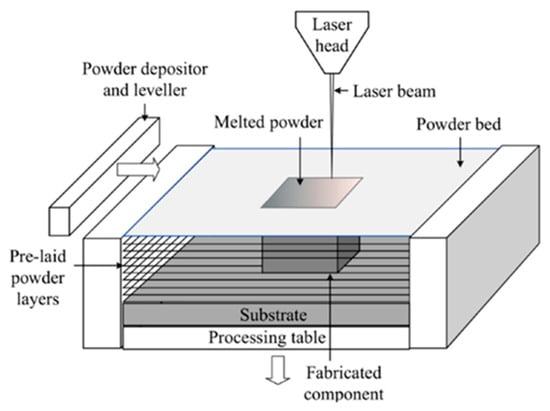
Figure 1. PBF schematic [31].
PBF technology usually uses an electron beam gun or a laser beam as an energy source, but other types of thermal energy sources can also be used. The most commonly used energy source in PBF is lasers. Many types of PBF technology have been developed, the most common of which are Selective Laser Sintering (PBF-LB/P, SLS), Electron Beam Melting (PBF-EB/M, EBM), Selective Laser Melting (PBF-LB, SLM), Selective Heat Sintering (SHS), Multi Jet Fusion (PBF-IrL/P, MJF), and Direct Metal Laser Sintering (DMLS). The full description of each of these PBF variants can be found in [32].
As for the materials to be used for PBF, materials that can be melted and re-solidified are suitable for this method. The most commonly used metals in PBF are steel, stainless steel, nickel-based alloys, aluminum, and titanium. Despite their great advantages, PBF components, like all AM techniques, also have some internal and external defects, namely high tensile residual stresses [33,34] anisotropic and inhomogeneous microstructure [35], a high degree of surface roughness [34], and porosity [12,36,37]. The fatigue performance of as-built materials is greatly affected by the combined effects of the as-built defects in the materials.
3. Processing Parameters
The success of PBF processing depends on many parameters, as shown in Figure 2. For this reason, PBF parameters are usually optimized to ensure a high quality of the final product. Often, PBF machine manufacturers offer their customers optimized parameters for a specific condition.
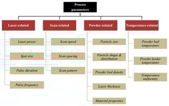
Figure 2. PBF processing parameters [36].
The dependence of the final product on many parameters increases the complexity of the process. For this reason, Jia et al. [38,39] and Sateesh et al. [40] combine laser power, scan speed, hatch spacing, and layer thickness/beam diameter into a single parameter called volumetric energy density, laser energy density, and linear laser energy density. For example, in the SLM process, the scan speed, laser power, hatch spacing, and layer thickness have the most influence [36], and many studies have used these parameters to increase the density of the final product [41,42]. The processing parameters in the PBF process can be calculated using the following equations:
where E is the energy density in J/mm2, P is the laser power in J/s; � is the scan speed in m/s; � is the hatch spacing in mm, � is the linear energy density in J/mm, � is the volumetric energy density in J/mm3; h is the hatch spacing in �m; and � is the layer thickness in �m.
�=���
�=��
�=��ℎ�
4. Mechanical Properties
To understand how build orientations and HT affect both the microstructure and mechanical properties of additively manufactured IN718, dog bone specimens were fabricated with four different build orientations 0°, 45°, 55°, and 90° [43]. The results of tensile tests showed that the highest yield stress and UTS were obtained at 55°, followed by 90°, while the highest elongation was observed at 45°. The results also showed that higher mechanical properties were obtained for vertically fabricated specimens than for horizontal specimens, which is contrary to the results obtained by Podgornk et al. [44] and Alsalla et al. [45].
Regarding aluminum alloys, Read et al. [46] studied the influence of the parameters used in the SLM process. The mechanical properties of the study were obtained using optimized parameters determined using a statistical approach called the design of experiments. Two different buildup directions (horizontal and vertical) were considered in this study. From the results of the tensile properties (see Figure 3), it was concluded that the buildup direction has only a minor influence on the tensile properties. However, compared to the die-casting alloy A360, higher tensile strength properties were obtained for both the vertical and horizontal orientations BD, except for elongation, which is three times lower. Table 1 shows the tensile strength properties of the specimens produced with different BD.
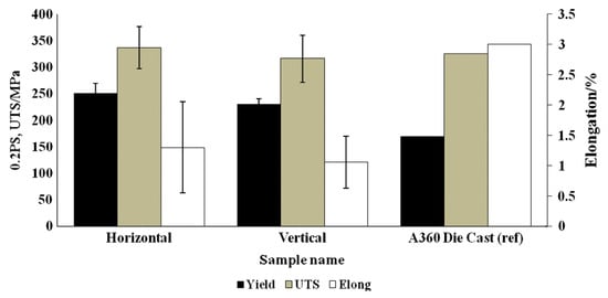
Figure 3. Comparison of tensile properties of SLM fabricated samples and die-cast A360 alloy [46].
Table 1. Tensile properties of PBF materials.
| Materials | UTS (MPa) | YS (MPa) | E (%) | ||||||
|---|---|---|---|---|---|---|---|---|---|
| 0° | 45° | 90° | 0° | 45° | 90° | 0° | 45° | 90° | |
| 316L [45] | 668 | 564 | 397 | 387 | 37 | 35 | |||
| MS1 [44] | 2000 | 2020 | 1850 | 1940 | 1935 | 1915 | 5 | 4.6 | 4.8 |
| 316L [47] | 630–635 | 610–630 | 460–475 | 450–470 | 50 | 60 | |||
| Ti6Al4V [48] | 833 | 851 | 783 | 812 | 2.7 | 3.6 | |||
This entry is adapted from the peer-reviewed paper 10.3390/met13101762
This entry is offline, you can click here to edit this entry!