Your browser does not fully support modern features. Please upgrade for a smoother experience.
Please note this is an old version of this entry, which may differ significantly from the current revision.
Mechanically stabilized earth (MSE) walls are recognized for their cost-effectiveness and superior performance as earth-retaining structures. The integration of internally reinforced walls has transformed soil preservation practices, garnering significant attention from the global technical community. The construction method of MSE walls has recently gained widespread popularity, likely due to its cost efficiency and simplicity compared to traditional externally reinforced walls.
- mechanically stabilized earth walls
- soil–structure interaction
- internally stabilized fill
- lateral displacements
1. Introduction
The history of retaining walls dates back to ancient Egypt when they were constructed to protect against the flooding of the Nile River. To combat erosion caused by the flooding, gabion-style retaining structures were built using reeds. These walls served not only as conduits for waterways on the land but also functioned to redirect Nile floods into reservoirs, proving to be efficient flood control solutions. Throughout history, an array of materials including sizable rocks, barrels filled with smaller stones, treated timber, cast-in-place concrete, and concrete slabs were employed in the construction of these retention walls. Mechanically stabilized earth (MSE) walls, a composite framework integrating soil and strengthening methods, were pioneered by Henri Vidal in the 1960s and gained popularity in the US during the 1970s [1][2]. These walls present benefits like reduced costs, construction simplicity, inherent stability that withstands settlement without fracturing, and improved seismic resistance in contrast to alternative retaining wall systems. Owing to these advantages, MSE walls have emerged as the favored choice for diverse applications [3]. They have been effectively utilized as embankments, coastal defenses, stabilizing elements for bridges (abutments), towers, buildings, industrial storage enclosures, roads, railways, and various other construction undertakings [4], as well as for conventional soil and rock mass retention purposes [5]. AASHTO criteria [6] recommend high-quality, free-draining granular materials for backfill in the construction of MSE walls. Yu et al. [7] stated that the performance of MSE walls is complex, making it difficult to simulate these walls effectively with numerical modeling approaches (such as the finite element and finite difference approaches). The intricate interactions between the soil and the supporting components, the soil and the exterior panels, and the incremental building process all contribute to this difficulty. Damians et al. [8] described the latest case study in which they implemented the finite element technique to model the behavior of an instrumented, 17 m high steel strip wall built in the USA [9].
Soil frequently comes into direct contact with structures, and its behavior under external dynamic forces such as seismic events or vibrations can profoundly impact the way the construction responds. The concept of dynamic SSI encompasses the relationship between the soil and the structure. In engineering design, it is a common assumption that the base of the wall possesses fixed support when evaluating the earthquake resistance of structures. However, this assumption is overly simplified and holds true only if the wall is supported by exceptionally rigid soil or hard rock strata [10]. Among the most important topics in the field of seismic engineering, SSI has received extensive focus internationally in the past few years [11]. Construction projects built on the ground surface are examples of an interrelated system that is subject to SSI effects. Initial developments date back to the late 19th century, but they did not fully evolve and reach their peak until the following decades and the first half of the 20th century. In the second half of the century; however, they advanced quickly owing primarily to the demands of the offshore and nuclear power industries, the introduction of powerful computers and simulation tools like finite elements, and the requirement for increased earthquake safety. Studies related to the interaction between soil and structure have demonstrated that a structure available on a loose base may respond dynamically differently than the same structure available on rigid strata [12][13]. The difference in vibrational force absorption between a flexible structure and the supporting surface is primarily attributed to stress wave radiation and hysteretic action. Numerous well-established analytical methods are accessible for computing the impacts of dynamic interactions between soil and structures [14]. The issue of soil–structure interaction becomes intricate when multiple edifices coexist in close proximity, as their structural responses within the ground influence one another. Owing to spatial limitations in urban areas and swift urban development, the construction of tall buildings grouped together has been progressively surging, particularly in regions with soft soil layers, such as the urban zones in Kobe, Japan [11]. In such scenarios, the energy released from shaking structures is transmitted to the soil and neighboring structures, leading to dynamic interactions among the buildings. Consequently, the dynamic characteristics and earthquake responses of a structure cannot be studied in isolation from those of nearby buildings.
2. An Overview and Applications of MSE Retaining Walls
Soil, being a natural material, exhibits various characteristics depending on its type. The cohesion (C) and angle of internal friction (Ø) are key parameters that define its properties. Dry soil, when unrestrained, often results in sloping profiles rather than vertical surfaces. In certain applications, such as bridge abutments, underwater walls, submerged walls, wing walls, and stabilized slopes, it becomes necessary to maintain the soil in a perfectly vertical position, particularly on either side of a roadway. This vertical support is achieved through the use of ground-retaining structures. These structures play a crucial role in keeping the soil in a vertical and stable position. Retaining frames were previously made of reinforced concrete and designed as gravity or cantilever walls, resulting in rigid or flexible structures incapable of withstanding significant variations in settlement without the support of pile foundations. As the level of soil that must be kept vertically straight increases and the subsoil layers weaken, the cost of reinforced concrete retaining walls increases considerably. In response to earth pressure, the foundation is prone to collapse [15][16]. However, porous or unstable underlying soils need significant construction and design challenges. The vertical length of these walls usually ranges from 3 to 12 ft (about 0.9 to 3.70 m), and based on the wall design, stresses close to the wall face can range from 4000 to 7000 psf (about 192 to 335 kPa). The increasing extent of the walls presents a number of geotechnical issues, including insufficient safety factors for global stability, bearing capacity, differential settlement, and others. This problem can be resolved using the MSE technique (Figure 1). This configuration is referred to as an MSE wall, whereas the front sections work as a basis for support and the soil serves as a strengthening structure (as shown in Figure 1). The facing of MSE walls is commonly constructed using various thin components, including precast concrete tiles, dry cast modular boards, metal sheets and plates, welded metal mesh, bonded wire mesh panels, shotcrete, hardwood lagging and columns, and bundled sheets of geosynthetics [17]. The soil behind the facing is then compacted and supported by materials such as steel strips or bars, welded wire mats, polymer surfaces, or geotextile supports, which mechanically stabilize the entire structure [18]. A facing structure facilitates the creation of perpendicular and sloping mechanically stabilized earth (MSE) walls. Often, the soil is positioned as an unreinforced layer between the stable section and the existing ground surface, forming what is termed “retained backfill”. In the construction of MSE walls, coarse soil is utilized as a foundational fill. These walls, classified as earth-retaining structures, comprise three main components: metallic or geosynthetic supports, facing elements, and soil-reinforced walls. As being developed in civil engineering over thirty years ago, MSE structures have gained popularity as a cost-effective alternative to traditional concrete-reinforced retention structures and started to spread to many nations and ended up being more widely used. MSE walls have emerged as the preferred method of earth retention filling due to their powerful load-bearing capacity, adaptability, and economy achieved by supplying granular fill and reinforcing components [19].
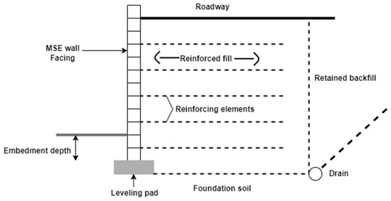
Figure 1. The essential parts of an MSE Wall.
In addition to the previously mentioned applications, MSE retaining walls find use as temporary walls for road construction, soil preservation, filtration systems for oil storage containers, protection walls around gas storage facilities, extensions for levees, capacity enhancements for dams, and delineation of storage spaces in areas with unsuitable soil conditions for construction. The construction of MSE walls involves a diverse range of methods, tailored to meet specific project requirements and site conditions. Key steps include site preparation, excavation for a level foundation, installation of reinforcements such as geogrids or steel strips, backfilling with appropriate material, incorporation of facings for structural support and aesthetics, ensuring proper reinforcement and facing connections, implementation of drainage systems, and strict adherence to quality control measures. Construction techniques may vary based on design needs, wall type, and available resources. It is essential to follow the guidelines provided by project engineers to ensure the construction of a secure and durable MSE wall.
Some previous studies focused on the numerical and experimental study of models for MSE walls. For instance, Burke et al. [20] used computational analyses on a complete geosynthetic soil reinforcement system by adopting the finite element technique. The model had a height of 2.8 m and a 20 cm thick earth foundation. It was subjected to Kobe earthquake vibrations with an amplitude of 0.4 g. The structure’s borders and facings were designed as linearly elastic materials. The geosynthetic material was modeled using an ambling surface model of power reinforcing roles, and the backfill and foundation soil were modeled using an existing plasticity approach. The research was carried out assuming 2D plane strain settings using a modified DianaSwandyne-II program.
3. Mechanisms of MSE Wall Failure
Although MSE walls are known for their reliability, ease of construction, and cost-effectiveness, the occurrence of MSE wall failures has become a concerning issue for various agencies that implement them. MSE walls exhibit two distinct forms of stability: internal stability and external stability. Consequently, addressing and discussing these two modes can be approached separately. Although the principle of soil reinforcement shares some resemblance to reinforced concrete, the interaction between soil and reinforcement differs significantly from the chemical bonding observed in steel-concrete structures. In the case of MSE walls, the interaction between soil and reinforcement relies on friction and interlocking of soil particles with the reinforcement aperture, creating a pseudo-cohesive effect, as depicted in Figure 2a [21]. The frictional characteristics and interlocking between materials depend on various factors, such as the crushability of soil particles and the surface roughness of reinforcement. For instance, the presence of water in the soil can act as a lubricant between particles, leading to a decrease in internal friction. The frictional and interlocking behavior is closely linked to the shear strength and the transfer of force in the reinforced materials. Additionally, the length and quality of reinforcement significantly impact the pullout resistance of the earth reinforcement [22]. For the MSE wall to resist external failures like overturning at its toe, sliding along the base, differential settlement, and loss of bearing capacity of the foundation, the earth reinforcement structure must function as an effective gravity retaining wall. Figure 2b illustrates a schematic representation of a typical reinforced soil retaining wall, indicating the forces involved in both internal and external stability analysis [23]. Despite making several assumptions, the behavior of MSE walls remains highly complex. As a result, engineers strive to develop standardized procedures and codes of practice for designing such walls. In general, the specifications AASHTO [6] and NCMA [22] provide the necessary criteria for earth reinforcement design to ensure it satisfies all failure modes.
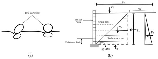
Figure 2. (a) The schematic of interaction between soil and (b) reinforcement and a reinforced soil retaining wall with the forces considered in the analysis of its external stability.
External stability in soil structures relies on their ability to withstand external forces based on their weight and stiffness. Earth reinforcement structures, when behaving like rigid bodies, exhibit external failure mechanisms similar to conventional gravity walls, including sliding failure, bearing failure, and overturning failure [24][25], as shown in Figure 3. Sliding failure primarily occurs at the base or foundation level. The numerical analysis shows that the backfill failure follows classical Rankine’s or Coulomb’s model, but the reinforced soil remains outside the failure envelope [22]. This supports treating reinforced soil as gravity walls. The key factors affecting sliding stability are the friction and interlocking between these zones, which depend on the weight of the reinforced soil, the contact surface between reinforcement and soil particles, and the area of reinforcement and foundation. The study on overturning stability [26] identifies key factors: wall height, unit weight of reinforced soil, friction angle of backfill, and surcharge load. Notably, there exists a close relationship between the failure modes of overturning and bearing capacity.
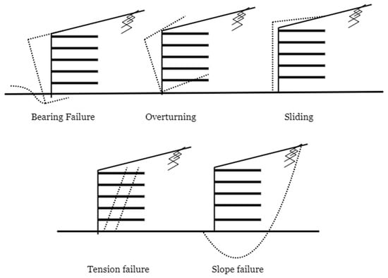
Figure 3. The primary way in which reinforced soil systems tend to fail is the principal mode of failure.
Internal stability is determined by the strength and stiffness of the reinforced soil mass. Experimental data demonstrate that reducing the spacing between reinforcements increases the soil’s stiffness and reduces tension within the reinforcement [27]. Accordingly, AASHTO requires the spacing of vertical soil reinforcement to be limited to 0.80 m. The design of reinforced soil retaining walls considers two critical factors: the bond rupture strength between the reinforcement and soil, and the strength of the reinforcement itself. The occurrence of failure in such walls is determined by the rupture of reinforcement and pullout strength (Figure 3). If the tensile force in the reinforcement exceeds the friction force between the reinforcement and soil, the reinforcement may be pulled out from the soil mass, leading to local failure. Pullout failure typically arises when the reinforcement length is insufficient to resist tension or when the soil’s strength is inadequate to handle the tension force [22]. Additionally, another potential failure mode occurs when the tensile force in the reinforcement surpasses the rupture strength of the reinforcement itself, resulting in elongation or breakage and causing rupture failure [28]. Currently, panel elements are widely utilized on the front face of earth reinforcement structures to enhance the strength and stability of the reinforced soil zone and mitigate surface erosion. The stiffness of the earth reinforcement facing has a significant impact on the tension failure of the reinforcement [27]. Reducing the reinforcement length in the reinforced soil zone moves the maximum stress position closer to the facing due to limited surface area for tension force distribution. Shorter reinforcement selection forces the maximum reinforcement load towards the facing blocks to ensure sufficient anchorage. However, the maximum tension force in the reinforcement is independent of reinforcement length [27]. The result indicates that the rupture failure surface of the reinforced soil is closer to the facing blocks than Rankine’s rupture failure surface. This rupture surface is another scenario that may lead to tension failure.
Friction between the soil and reinforcement plays a crucial role in determining the pullout force, acting as a pseudo-cohesion for the earth reinforcement. If the reinforcement length is too short to mobilize sufficient friction force against the prevailing tensile force, pullout failure often occurs at the end of the reinforcement, particularly at the top of the wall. AASHTO recommends a safety factor of 1.5 for the pullout failure mode and requires a minimum reinforcement length of 0.9 m [6].
It is important to consider that the Ultimate Limit State (ULS) of MSE walls involves evaluating the wall’s structural integrity under severe loading conditions to ensure it can withstand the forces without failure. Important considerations at the ULS include the wall’s bearing capacity, resistance to sliding and overturning, pullout resistance of reinforcement, and overall stability, including seismic factors and interactions with adjacent structures. For instance, an MSE wall supporting a highway embankment is designed to withstand the maximum traffic loads and seismic forces. The wall’s facing is engineered to provide adequate friction with the underlying soil, preventing sliding or overturning during extreme loading. On the other hand, the Serviceability Limit State (SLS) of MSE walls focuses on their performance under normal conditions to maintain functionality and aesthetics. Key aspects at the SLS are deflection control, cracking prevention in the facing and reinforcement, settlement avoidance, and proper water drainage to prevent hydrostatic pressure and maintain serviceability. For example, an MSE wall used for residential landscaping is designed to meet specific deflection limits for a smooth appearance. The facing material is chosen to resist cracking, and an effective drainage system is installed to avoid water accumulation and potential damage.
4. Advantages and Disadvantages of MSE Retaining Walls
The application of mechanically stabilized earth (MSE) walls, which come in diverse dimensions and arrangements, hinges on their designated function and particular surroundings. These walls capitalize on their intrinsic gravitational forces to resist external factors like lateral earth pressures, water pressures, and seismic occurrences. This allows for the efficient dispersion of bearing pressure across a substantial area. When contrasted with concrete walls, MSE retaining walls present advantages in terms of cost efficiency and their capacity to withstand greater overall settlements and differential movements without experiencing failure. Their construction is also simpler and quicker, as they do not require external structures like scaffoldings or curing time. MSE walls are often capable of withstanding complex dynamic loads, including earthquakes, as well as static loads [21]. Due to their cost-effectiveness and strength, MSE structures are highly favored by contractors and architects. These walls present numerous advantages, including ease of construction, limited reliance on heavy equipment, swifter assembly in comparison to traditional concrete walls, and the potential to utilize more land area for construction purposes. Furthermore, MSE walls eradicate the necessity for specialized labor, wall finishing, and extensive site preparation. They can be installed in tight spaces or areas where building a concrete wall would be challenging. However, this approach may reduce the amount of land required. While MSE walls exhibit high resilience to earthquake forces, they are susceptible to elastomeric distortion. Combined with additional reinforcing components, MSE walls can reach heights of 60 ft (about 18 m) and could be compared to other tall retaining structures. Since MSE walls might be available in a variety of dimensions and forms, their use can eliminate the requirement for drilling foundations, enabling their use in areas with shallow ground [22]. The design of MSE walls comes with certain drawbacks, such as the need for a minimum diameter to achieve stability. Moreover, the availability of coarse-grained soil for the reinforced soil mass can be costly, making the construction process less profitable in regions with a scarcity of granular material. Proper drainage systems must also be incorporated. Additionally, the reinforced components must be designed to withstand weathering and deterioration, which could potentially diminish the mechanical advantages of the composite framework.
5. Factors Affecting Horizontal Displacement of MSE Walls
MSE walls serve as an alternative to traditional gravity walls, offering simplified construction methods, aesthetic design, and cost-effective options. To ensure satisfactory performance, thorough investigation of building and design is necessary. During MSE wall construction, reinforcements are layered into the backfill soil. This reinforced material utilizes the relative movement between the reinforcement and soil to withstand soil stress induced by the retained soil. As a result, the interaction that occurs between an MSE wall’s elements, particularly the interaction between soil and reinforcement, determines the wall’s effectiveness [23]. Additionally, the structure should give careful consideration to the ground stress brought on by preserved soil [22]. Federal Highway Administration [22] and AASHTO [6] proposed a factor of 0.7 of the height of the wall (H) with a minimum of 2.4 m for the length of reinforced soil in current construction methods. Even so, a minimum reinforcing length of 0.6 H was mandated by the National Concrete Masonry Association [24]. The implementation of the required reinforcing length could be limited in cases when natural formations of stones, artificial shoring infrastructure, or similar retaining walls are evidently associated with an MSE wall [29]. Stability problems and excessive lateral movement may arise in these circumstances. The choice of backfill soil is crucial along with reinforcing length, since Soong and Koerner [30] documented 20 cases of geosynthetic-reinforced wall collapses brought by the poor functioning of restricted backfill. Such unacceptable horizontal movement or possibly the failure of an MSE wall can result from an insufficient amount of strengthened soil. Therefore, since in many situations there is not much space back the wall, lateral movement brings a significant risk [31].
Kibria et al. [28] studied how strengthening the soil affected the MSE wall’s instability. The researchers used two inclinometers, which were set up on the scene as a component of the forensic examination to track the future movement of the MSE wall. The inclinometer readings revealed that throughout the examination time, the wall maintained moving at a regular rate of 4.5 mm/month. To analyze the impacts of soil strengthening on horizontal displacement at various wall heights and backfill conditions, a parametric approach was carried out. Findings from the FE simulations were employed in a statistical evaluation software for evaluating sensitivity. Depending on the assessments, it was shown that reinforcement length and stiffness had a significant impact on how much MSE walls would move horizontally at a given height. According to the analysis, it was determined that one of the reasons impacting the durability of the wall may be insufficient reinforcing length. At a fixed wall height, horizontal movement reduced when reinforcement strength, length, and backfill soil friction angle increased. For a wall height of 4 m, it was found that the influence of reinforcement stiffness was insignificant. On the other hand, with an 8 m wall elevation, the horizontal displacement expanded to 389 mm at reinforcement stiffness and length (L) of 250 kN/m and 0.6 H, respectively. According to the fluctuations in movement with reinforcement length, displacement significantly decreased with an increase in the L/H ratio from 0.5 to 0.7.
Abdelouhab et al. [29] built a 2D computer model of an MSE wall in the finite difference program FLAC 2D. It could be found that the MSE walls’ durability and deformations are most significantly impacted by the soil shear strength factors, and the capability of adhesion is increased by using composite strips that are two times larger than metallic strips. When employing high-adherence synthetic strips, the stability is considerably higher. Additionally, the parametric analysis of the strip modulus of elasticity reveals, for the longitudinal stiffness, a value less than 3500 kN/m2 for the wall face. This factor has a considerable influence on wall durability and displacement. Moreover, the analysis of interface characteristics reveals that variations in interface shear stiffness significantly affect wall displacement fluctuations. For an accurate assessment of structural movements, the authors recommend obtaining an appropriate estimate of this variable, such as through laboratory pullout tests, for each type of reinforcement. Wang et al. [31] used field investigations to assess the load distribution features of MSE walls during cyclical load conditions, and implemented computational models to assess the influence of the length of reinforcement, the friction factor of the reinforcement–soil interface, as well as the strength of reinforcement regarding the stress-distribution attributes of MSE wall. The findings indicated that a vertical dynamic soil pressure exhibits a discernible diminishing pattern ranging from high to low throughout the wall height while the number of load cycles increases. Throughout the length of reinforcement, the vertical dynamic soil pressure goes up first before decreasing. Additionally, the stress-distribution angle of the MSE wall does not alter significantly as the load cycles reach beyond 100,000; the upper section maintains at 35~79°, and the central part maintains at 47~68°. In MSE walls, the depth of stress distribution has a significant impact, approximately 1.13 times the overall wall height. The dimension and modulus of the reinforcement also influence the stress distribution in the MSE wall, with their effects ranking second and third, respectively.
This entry is adapted from the peer-reviewed paper 10.3390/civileng4030053
References
- Mitchell, J.K. North American practice in reinforced soil systems. In Proceedings of the ASCE Conference on the Design and Performance of Earth Retaining Structures, Ithaca, NY, USA, 18–21 June 1990; pp. 3233–3346.
- Jones, C. Earth Reinforcement and Soil Structures; Thomas Telford: Thomas Telford; ASCE Press: London, UK; New York, NY, USA, 1996.
- Christopher, B.R.; Leshchinsky, D.; Stulgis, R. Geosynthetic-Reinforced Soil Walls and Slopes: US Perspective. In Proceedings of the Geo-Frontiers Congress, ASCE, 12, Austin, TX, USA, 24–26 January 2005.
- Han, J.; Leshchinsky, D. Analysis of back-to-back mechanically stabilized earth walls. Geotext. Geomembr. 2010, 28, 262–267.
- Adams, M.; Nicks, J.; Stabile, T.; Wu, J.; Schlatter, W.; Hartmann, J. Geosynthetic Reinforced Soil Integrated Bridge System, FHWA Synthesis Report, USA; 2011; 68p. Available online: https://www.semanticscholar.org/paper/Geosynthetic-Reinforced-Soil-Integrated-Bridge-Adams-Nicks/49ddb880c987cea8d6a328dc94dd7f4ff41f6ea8 (accessed on 28 August 2023).
- AASHTO. Standarad Specifications for Highway Bridges (17th Edition) Retaining Walls; American Association of State Highway and Transportation Officials, Inc.: Washington, DC, USA, 2002.
- Yu, Y.; Bathurst, R.J.; Miyata, Y. Numerical analysis of a mechanically stabilized earth wall reinforced with steel strips. Soils Found. 2015, 55, 536–547.
- Damians, I.P.; Bathurst, R.J.; Josa, A.; Lloret, A. Numerical analysis of an instrumented steel reinforced soil wall. ASCE Int. J. Geomech. 2015, 15, 04014037.
- Runser, D.J.; Fox, P.J.; Bourdeau, P.L. Field performance of a17m- high reinforced soil retaining wall. Geosynth. Int. 2001, 8, 367–391.
- Jonathan, P.S.; Fenves, J.L.; Seed, R.B. Seismic Soil-Structure Interaction in Buildings. II. Empirical Findings. J. Geotech. Geoenvironmental Eng. 1999, 125, 38–48.
- Al-Jeznawi, D.; Jais, I.B.M.; Albusoda, B.S.; Khalid, N. Numerical Assessment of Pipe Pile Response under Seismic Excitation. Al-Nahrain J. Eng. Sci. 2023, 26, 96–101.
- Chopra, A.K.; Gutierrez, J.A. Earthquake response analysis of multistory buildings including foundation interaction. Earthq. Eng. Struct. Dyn. 1974, 3, 65–77.
- Iguchi, M. Dynamic interaction of soil–structure with elastic rectangular foundation. In Proceedings of the Fifth Japanese Earthquake Engineering Symposium, Tokoyo, Japan; 1978; pp. 457–464.
- Wolf, J.P. Dynamic Soil–Structure Interaction; Prentice Hall: New York, NY, USA, 1985.
- Zainab, S.A.K.; Zainab, A.M.; Jafer, H.; Dulaimi, A.F.; Atherton, W. The effect of using fluid catalytic cracking catalyst residue (FC3R) as a cement replacement in soft soil stabilisation. Int. J. Civ. Eng. Technol. 2018, 9, 522–533.
- Hussain, A.J.; Al-Khafaji, Z.S. The fields of applying the recycled and used oils by the internal combustion engines for purposes of protecting the environment against pollutions. J. Adv. Res. Dyn. Control Syst. 2020, 12, 666–670.
- Muteb, H.H.; Falah, M.W. Mechanically Stabilized Earth MSE Walls Applications: Review. IOP Conf. Ser. Earth Environ. Sci. 2021, 856, 012031.
- Al-Khafaji, Z.S.; AL-Naely, H.K.; Al-Najar, A.E. A review applying industrial waste materials in stabilisation of soft soil. Electron. J. Struct. Eng. 2018, 18, 16–23.
- Anderson, P.L.; Gladstone, R.A.; Brabant, K.; Sankey, J. Back-to-Back MSE Walls–A, Comprehensive Understanding. In Innovations in Geotechnical Engineering; ASCE: Reston, WV, USA, 2018; pp. 431–447.
- Burke, C.; Ling, H.I.; Liu, H. Seismic response analysis of a full-scale reinforced soil retaining wall. In Proceedings of the 17th ASCE Engineering Mechanics Conference, Newark, DE, USA, 13–16 June 2004.
- Coduto, P.D. Foundation Design Principles and Practices; Prentice Hall: New York, NY, USA, 2001; p. 738.
- Desai, C.S.; El-Hoseiny, K.E. Prediction of field behavior of reinforced soil wall using advanced constitutive model. J. Geotech. Geoenviron. Eng. 2005, 131, 729–739.
- Lim, C.S.; Tan, S.M. Collapse of a reinforced soil segmental retaining wall. IEM-GSM Oktoberforum 2005.
- Leshchinsky, D.; Han, J. Geosynthetic reinforced multitiered walls. J. Geotech. Geoenviron. Eng. 2004, 130, 1225–1235.
- Collin, J.G. Design Manual for Segmental Retaining Walls, 2nd ed.; National Concrete Masonry Association (NCMA): Herndon, VA, USA, 2002.
- Uppakarn, T. Review: Failure Mechanism of Earth Reinforcement Structure; Prince of Songkla University: Songkhla, Thailand, 2011; Available online: https://www.researchgate.net/publication/292835485_Review_Failure_mechanism_of_earth_reinforcement_structure (accessed on 30 June 2023).
- Bilgin, Ö.; Kim, H. Effect of soil properties and reinforcement length on mechanically stabilized earth wall deformations. In Proceedings of the Earth Retention Conference, ASCE, Bellevue, DC, USA, 1–4 August 2010; pp. 556–563.
- Kibria, G.; Hossain, S.; Khan, M.S. Influence of Soil Reinforcement on Horizontal Displacement of MSE Wall. Int. J. Geomech. 2014, 14, 130–141.
- Abdelouhab, A.; Dias, D.; Freitag, N. Numerical analysis of the behaviour of mechanically stabilized earth walls reinforced with different types of strips. Geotext. Geomembr. 2010, 29, 116–129.
- Soong, T.; Koerner, R.M. Geosynthetic Reinforced and Geo-Composite Drained Retaining Walls Utilizing Low Permeability Backfill Soil; GRI Rep. 24; Geosynthetic Research Institute: Folsom, PA, USA, 1999.
- Wang, H.; Ma, J.; Yang, G.; Wang, N. Study of Stress Distribution Characteristics of Reinforced Earth Retaining Walls under Cyclic Loading. Appl. Sci. 2022, 12, 10237.
This entry is offline, you can click here to edit this entry!