Your browser does not fully support modern features. Please upgrade for a smoother experience.
Please note this is an old version of this entry, which may differ significantly from the current revision.
5G Cell Search (CS) is the first step for user equipment (UE) to initiate communication with the 5G node B (gNB) every time it is powered ON. In cellular networks, CS is accomplished via synchronization signals (SS) broadcasted by gNB. 5G 3rd generation partnership project (3GPP) specifications offer a detailed discussion on the SS generation at gNB, but a limited understanding of their blind search and detection is available.
- 3GPP
- 5G cell search
- 5G physical layer
- RFNoC
1. Introduction
In a cellular network, user equipment (UE) performs initial access (IA) to establish communication with the base station (BS) every time it is powered ON [1,2,3,4,5,6]. The IA comprises the downlink and uplink synchronizations. The downlink synchronization involves the cell search (CS), and acquisition of minimum system information (MSI) at the UE [2,7,8,9]. The first step, CS, allows the UE to obtain cell identity and synchronize with the BS in terms of symbol, slot, subframe, and frame timings [7,8,9]. After the CS, MSI acquisition provides information such as access type (barred, restricted, or unrestricted), carrier frequency and bandwidth, cell selection information (minimum receiver level), scheduling information, downlink/uplink configurations, etc. [2,10,11,12]. The uplink synchronization, via physical random access channel (PRACH), allows the base station to locate and instruct the UE to fine-tune the uplink timings such that uplink transmissions from multiple UEs are aligned in time irrespective of their distances from base-station [10,13,14]. In [15], CS is moved from UE to BS via code-book-based approach. However, this approach is not compatible with existing 3GPP standards.
5G 3rd generation partnership project (3GPP) specifications offer a detailed discussion on the SS generation at gNB, but limited understanding about their blind search and detection at UE is available [7,8,9,10,16,17,18]. Historically, it is left to be designed by equipment manufacturers.
The CS in 5G substantially evolved from 4G Long Term Evolution (LTE) [19,20,21,22,23]. The significant difference is the location of SS in the frequency domain. In 4G LTE, the SS is transmitted over the subcarriers in the middle of the carrier [19]. In 5G, the location is not fixed and is unknown, which means the UE needs to blindly search the SS over the entire carrier bandwidth [10]. To simplify the blind search, 3GPP introduced Global Synchronization Channel Number (GSCN) in 5G, which pre-defines possible positions where gNB can transmit SS. The SS bandwidth and overall transmission bandwidth in 5G are significantly wider; hence, SS detection requires multiple large-size correlators [4]. This makes the blind search computationally complex and time-consuming. Deep learning for CS may not be suitable for low latency applications [24]. Other blocks of the CS physical layer (PHY), including message generators, channel encoders, data modulators, scramblers, interleaves, and their counterparts in the receivers, are redesigned in 5G [25,26]. Thus, efficient design of 5G CS and in-depth performance analysis are essential to understand computational complexity and identify the limitations for future standard releases.
2. Specifications of 5G CS
2.1. 5G CS PHY
Researchers consider the n78 frequency band (3300–3800 MHz) in the frequency range 1, i.e., FR1 (410–7125 MHz) as it is being widely chosen for initial deployment of the 5G networks [5,6]. As per the 3GPP specifications, the maximum transmission bandwidth in the n78 band is 100 MHz, and sub-carriers (SC) spacing (SCS) is fixed to 30 kHz for SS [17]. Thus, the maximum number of SC in the n78 band is 3276. In 5G, a resource block (RB) is the smallest bandwidth unit for resource allocation and 1 RB consists of 12 SCs. Thus, the maximum number of RBs available in the n78 band is 273.
The 5G PHY is based on orthogonal frequency division multiplexing (OFDM) based waveform modulation [25]. Each OFDM symbol consists of the number of SCs which must be a power of two due to IFFT/FFT operations. This results in 4096 SCs per OFDM symbol in n78 [17]. In the time domain, each frame duration is 10 ms, and it consists of 10 sub-frames. Each sub-frame consists of 2 slots, and each slot consists of 14 OFDM symbols. Then, a single frame of 10 ms comprises 280 OFDM symbols. Then, the symbol duration is 33.33 μs with a cyclic prefix size of 2.86 μs for the first symbol of each slot and 2.34 μs for the remaining 13 symbols. Different size of cyclic prefix allows a common frame structure for multiple SCS newly introduced in 5G [5,25].
The SS signals are transmitted in a burst, known as SS burst (SSB), and the size, duration, and periodicity of the SSB depend on the operating frequency range. For n78, SSB is transmitted in every other frame, and each SSB comprises 8 SS [7,8,9,10,16,18]. In a frame, the starting OFDM symbol of the SS is {4,8,16,20,32,36,44,48}. The duration of each SS is 4 OFDM symbols which means SSB spans over 52 OFDM symbols in a frame of 280 symbols.
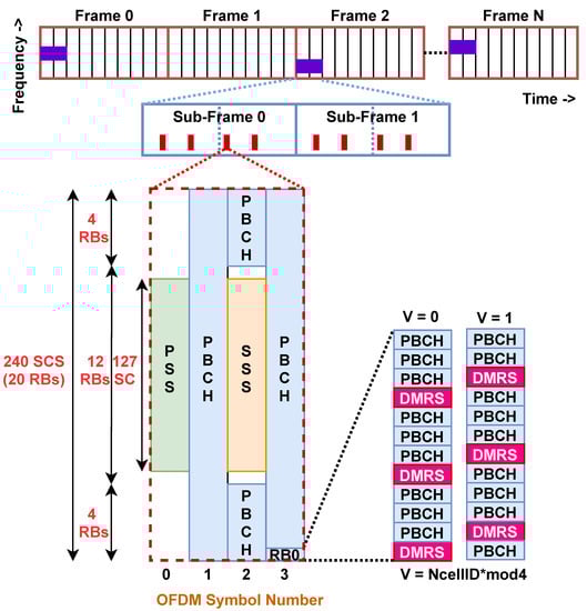
Each SS consists of 240 sub-carriers (SC) in the frequency domain, i.e., 20 resource blocks (RBs) and 4 OFDM symbols in the time domain [7,8,9,10,16,18]. As shown in Figure 1, the middle 127 SC of the first and third OFDM symbols are occupied by PSS and SSS, respectively. Since PSS and SSS are the first signals detected by UE during IA, they are carefully designed to enable blind detection with high reliability. 3GPP has adopted m-sequences to generate PSS 𝑑𝑃𝑆𝑆(𝑛) and SSS 𝑑𝑆𝑆𝑆(𝑛), 0≤𝑛<127 [16]. The rest of the 113 SCs of the first symbol are fixed to zero. The PSS and SSS allow the UE to detect the physical cell ID (PCI). In 5G, there are 3 candidate PSS sequences and 336 candidate SSS sequences which means the PCI range is from 0 to 1007 [16,18]. In the third symbol, there are 7 upper and 6 lower SC adjacent to the SSS fixed to zero, and the remaining SCs are occupied by a physical broadcast control channel (PBCH) carrying MIS and DMRS. The DMRS occupies 25% of the remaining SC, i.e., 144 SC. Since DMRS is quadrature phase shift keying (QPSK) demodulated, it consists of 288 bits which are generated using 3GPP defined pseudo-random sequence generator using two parameters: (1) PCI, 𝑁𝐶𝑒𝑙𝑙𝐼𝐷, and (2) SS index, 𝑆𝑆𝑖, of the SS in SSB, 𝑆𝑆𝑖 𝑖∈{1,2,…,8} [16,18]. At UE, DMRS is detected after PSS and SSS detections which means DMRS allows estimation of the SS index which is critical for a frame, sub-frame, slot, and symbol synchronization. DMRS also allows channel estimation for MIS reception via PBCH [11,12,23].
The location of all SS in SSB among 4096 SCs is not fixed in 5G and it is decided by the GSCN value. Furthermore, gNB can dynamically change the GSCN of the SSB. As per 3GPP specifications, there is a one-to-one mapping between the GSCN value and corresponding SSB center frequency [16,18]. In n78, the GSCN range is from 7711–8051 and the frequency resolution is 1.44 MHz. For example, the carrier frequency of 3305.28 Mhz is assigned a GSCN of 7711. Then, the GSCN of 7712 corresponds to the carrier frequency of 3305.28 + 1.44 = 3306.72 MHz. The last GSCN of the n78 band is 8051 and it corresponds to 3794.88 MHZ [16,18]. Such a GSCN raster of 1.44 MHz resolution allows UE to quickly detect SS by limiting the search over a limited number of center frequencies compared to the search over carrier frequencies with a channel raster of 15 kHz resolution.
2.2. Review: Mapping of 5G CS PHY on Hardware
The design, theoretical analysis, and simulation-based performance evaluation of 5G PHY have been an active research topic in the last few years [7,8,9,13,14,29,30]. Various works on the design and optimization of PHY sub-blocks such as channel encoders [31,32,33,34], OFDM modulator [35,36], beamforming [37,38] and channel estimation [39,40,41] have been explored to improve the PHY performance compared to 4G PHY. However, only a few works have focused on 3GPP standards and further improvements without compromising the compatibility with existing and previous standards [7,8,13,14,19,30]. From 5G CS perspectives, works in [8,9] provide an in-depth understanding of the SS generation while [7] offers an innovative intelligence-based CS approach. However, these works do not highlight the challenges in SS detection and applications of SS detection for timing synchronization.
Another important aspect of 5G PHY deployment is an efficient implementation on the software and hardware platforms. Compared to 4G, there are numerous scenarios that have resulted in the split of PHY depending on positions of radio, distribution, and centralized units [42,43,44]. This demands hardware-software co-design of the PHY. In [45,46], authors have explored the hardware-software co-design of IEEE 802.11 PHY on Zynq system-on-chip (SoC) platform. In [35,47], authors have explored reconfigurable OFDM waveform with dynamically controlled out-of-band emission. In [48], authors have proposed reconfigurable OFDM-based PHY to support multi-standard operations. However, none of these works consider 3GPP compatible 5G PHY. The work in [26] is limited to OFDM-based transceivers but does not consider various control and data channels in 5G while the work in [49] is limited to software-based CS implementation using USRP.
This entry is adapted from the peer-reviewed paper 10.3390/chips2040014
This entry is offline, you can click here to edit this entry!