Your browser does not fully support modern features. Please upgrade for a smoother experience.
Please note this is an old version of this entry, which may differ significantly from the current revision.
Subjects:
Engineering, Mechanical
A lattice structure is made by a unit cell that is repeated in the space, making a larger functional structure; thus, it is a peculiar kind of cellular structure. The basic idea of cellular structures evolved from natural organic structures such as bamboo, bone, cork, etc. According to the literature, in many applications, lattice structures have been found to be superior to their other cellular counterparts, such as foam and honeycomb structures.
- lattice structures
- cellular structures
- topology
- cell’s element geometry
- cell’s size
- replication pattern
- mechanical behavior
- TPMS
1. Introduction
For the very first time, the concept of cellular structures was introduced by Gibson and Ashby [1,2]. Initially, they classified cellular structures into foam (open cell and closed cell) and honeycomb. Foam’s cell shape and pattern are usually defined by random distributions, while the honeycomb structure has a regular 2D hexagonal unit cell and the cell walls are uniformly oriented in the space. In open-cell foam, the cells are not totally enclosed by their walls, while in closed-cell foam, the cells are entirely enclosed by their walls. Despite these differences, the component is always defined from a micro/mesoscale cell, replicated to fill the overall macroscale volume. However, the cellular structures were later classified [3,4] into three main categories: foam, honeycomb, and lattice.
According to the literature, in many applications, lattice structures have been found to be superior to their other cellular counterparts, such as foam and honeycomb structures. A more in detail strength-to-weight ratio and mechanical performance, such as energy absorption or compliance, is generally better due to the tailored shape of the cell and the replication pattern [6,7]. Moreover, they can support functional designs, such as heat exchangers or fluid conveyors, as demonstrated in [8]. More recently, taking inspiration from natural organic structures such as bones and plant stems, the concept of graded densities increased the spread of lattice structures, for example, being used to optimize load distributions [9,10]. It also furthers the evolution towards multigrade lattice structures, coupled with different materials. From this, the concept of multigrade and multifunction lattices arises. These are the solutions in which not only the type of unit cells but also the cell’s density and materials are distributed to gain a specific performance or function. Multigrade lattice structures have numerous applications, i.e., to enhance stiffness [11], to increase energy absorption capability [12,13,14,15,16,17], to improve thermal exchange efficiency [18,19], to tailor specific behaviors such as a negative Poisson’s ratio [20,21,22], etc.
According to [23], lattice structures may be classified based on:
-
The unit cell’s characteristics, which include topology, cell’s element geometry, and cell’s size.
-
The characteristics of the cell’s replication pattern.
However, in [26,27], the classification of the lattice structure has been discussed in more detail; therefore, the latest classification of lattice structure can be shown in Figure 1.
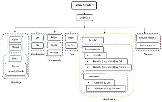
Figure 1. Classification of lattice structure.
2. Unit Cell Characteristics
A topology-based classification defines whether the cells are closed or open and how many cells’ faces are open, while a cell’s element geometry, according to [2], distinguishes between cells made of struts and cells made of plates or shells, introducing a structural behavior classification of the cells. A cell’s element geometry includes a geometrical definition of the structural elements (sections, number of edges, …) [6,7,23,28], and the size, including all the dimensional elements that define a cell (e.g., section size and axial length for struts, length, width, and thickness for plate/shell). The cell’s element geometry, indeed, may also constrain the topology of the cell (e.g., strut cells are always open, shells and plates may be open with different geometrical shapes). Concerning the cell’s size, the distinction between homogeneous and heterogeneous defines whether the structural elements of the cell are constant or not. Figure 2 and Figure 3 show an overview of strut-based and surface-based lattice cells, respectively.
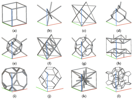
Figure 2. Beam Lattice (generated with nTop and the colored lines show the 3D reference system useful for comparison): (a) Simple Cubic Cell; (b) Body Centered Cubic Cell; (c) Face Centered Cubic Cell; (d) Diamond Cell; (e) Fluorite Cell; (f) Octet Cell; (g) Truncated Octahedron Cell; (h) Re-entrant Cell; (i) Truncated Cube Cell; (j) Kelvin Cell; (k) Iso Truss Cell; (l) Weaire–Phelan Cell.
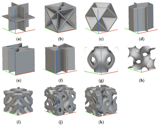
Figure 3. Surface-based lattice (generated with nTop and the colored lines show the 3D reference system useful for comparison): (a) Simple Cubic Foam Cell; (b) Body Centered Cubic Foam Cell; (c) Face Centered Cubic Foam Cell; (d) Hexagonal Honeycomb Cell; (e) Triangular Honeycomb Cell; (f) Re-entrant Honeycomb Cell; (g) Schwartz Cell; (h) Gyroid Cell; (i) Diamond Cell; (j) Split-P Cell; (k) Lidinoid Cell.
Concerning strut-based unit cells, Simple Cubic (SC), Body-Centered (BC), and Body-Centered Cubic (BCC) are derived from the same cubic cell, just with an increasing number of beams [23,29,30,31]. The Octet Truss (OT) cell comes from the face-centered cell [32]. Other frequently used cells are the modified Gibson–Ashby (GA) and the modified Wallach–Gibson (WG) cells [6,7,23,28]. Figure 2h shows an example of a re-entrant cell.
It is an auxetic cell designed to present a negative Poisson’s ratio, which means that the cell enlarges when stretched and contracts when compressed [33,34,35,36].
Concerning surface-based unit cells, we can distinguish between plate and shell cells, and, more generally, surface-based cells like Triply Periodic Minimal Surface (TPMS). In [37], according to Gibson, the plate cells were investigated connecting some struts of Figure 2 with plates, as shown in Figure 3a–c. These solutions, although may be replicated as periodic and regular, are often considered a type of closed foam, as commented in [38]. A honeycomb lattice [28], shown in Figure 3d–f, may have unit cells that are hexagonal or triangular; recently, the re-entrant configurations have also been studied.
Triply Periodic Minimal Surfaces (TPMSs) are being widely investigated. They are bio-inspired cells with boundary surfaces with a zero-mean curvature at every point [39,40]. TPMSs are relevant as functionally graded structures since their geometric characteristics allow them to reach different surface-related properties (e.g., manufacturability, fluid permeability, electrical and thermal conductivity). According to the procedure adopted to model them, they can be classified as skeletal and sheet TPMSs. In the first case, a volume is trimmed by the TPMS and the remaining part is thinned (skeletonized) with an assigned thickness. In the second case, the TPMS represents the shell sheet that is subsequently thickened.
TPMS Formulation
From a mathematical point of view, a TPMS is an infinite surface, periodic along three mutually orthogonal directions, which satisfies the following conditions:
where k1 and k2 stand for the principal curvatures of the surface at a general point P. Many authors studied the theoretical formulations of TPMS, starting from different mathematical points of view. In [39], the level set method, an approach applied in mechanical engineering to optimize topology in accordance with structural requirements, is adopted to study five TPMSs, namely Primitive, Gyroid, IWP, Diamond, and Fisher–Koch. Assuming that a TPMS may be described by a sum of Fourier terms and that its leading term is the basis function of the TPMS, i.e., φ(x,y,z), the TPMS can be achieved as iso-level curves:
Subjected to Equation (1). Equations (3)–(5) show three formulations achieved according to such reasoning, reported in Figure 3g–i.
Schwartz primitive:
Schwartz diamond:
Gyroid:
where:
The 𝐿𝑥, 𝐿𝑦, and 𝐿𝑧 are the unit cell size in the X, Y, and Z directions. x, y, and z are the periodicities, while X, Y, and Z are the cell’s repetitions.
3. Characteristics of the Cell Replication Pattern
Characteristics of the replication pattern are concerned with the cell’s connection, orientation, and density in the space, as discussed in [7,41,42]. It also pertains to the cell size in the sense that the cell’s length may also change along the replication pattern randomly or according to a gradient as a request of the design intent (e.g., functionally graded lattice structures) [43,44,45,46].
Replication patterns can be:
-
Regular.
-
Pseudo-regular.
- ○
-
Hybrid,
- ○
-
Warped (or gradient) by cell size,Warped (or gradient) by thickness,
- ○
-
Conformal.
-
Stochastic.
- ○
-
Random by cell size,
- ○
-
Random also by thickness.
In a regular replication pattern, no changes regarding the unit cell characteristics occur at all (Figure 4). Hybrid patterns include different unit cells that may also have different geometric characteristics (Figure 5). They can be considered as part of pseudo-regular patterns that provide several replications based on the variation in the unit cell’s size.

Figure 4. Examples of regular replication patterns (generated with nTop): (a) Kelvin Cell; (b) Re-entrant Cell; (c) Re-entrant Honeycomb Cell; (d) Split-p Cell.
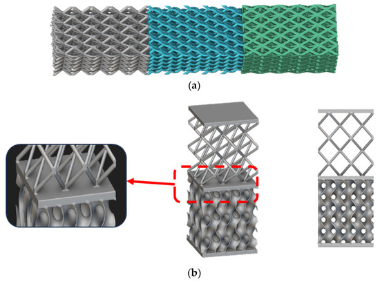
Figure 5. Examples of hybrid replication patterns achieved by changing the unit cells (generated with nTop): (a) BCC Lattice + Diamond Lattice + FCC Lattice; (b) BCC lattice + Gyroid TMPS.
Pseudo-regular patterns also include warped (gradient) and conformal structures (Figure 6). The gradient by cell size is a replication pattern that provides a structure in which the unit cell’s size varies gradually along a specified direction, while the thickness of the elements remains the same (Figure 6a). In the case of the gradient by thickness, the structure maintains a constant cell size, but its thickness is changed (Figure 6b). Conformal lattice structures consist of cells changing in length and shapes non-homogeneously, so that the replication pattern may follow the boundaries of the part (Figure 6c) [47,48].
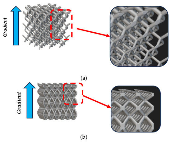
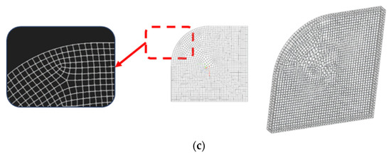
Figure 6. Examples of pseudo-regular pattern replications (generated with nTop): (a) BCC cells with gradient by thickness; (b) BCC cells with gradient by cell size; (c) Simple cubic cells conformal.
In stochastic patterns, the cell size varies randomly, while the thickness remains the same. However, in stochastic random patterns, the thickness varies randomly or along a gradient throughout the structure (Figure 7).
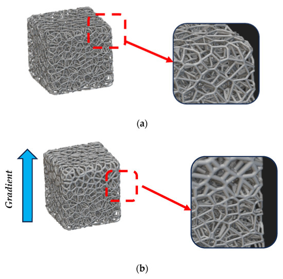
Figure 7. Examples of stochastic replication patterns (generated with nTop): (a) cell’s size variation; (b) thickness variation by gradient.
4. Mechanical Behavior
The mechanical behavior of cellular materials is affected by the micro/mesoscale characteristics (unit cell and replication pattern), in addition to the macroscale topology and shape of the overall component [49,50]. This means that the local behaviors determine the global mechanical response and its related performance. Based on their local mechanical response, the lattice structure is generally classified into [51]:
-
Bending dominated.
-
Stretch dominated.
Bending-dominated structures react locally with a bending deformation. This makes them extremely useful (such as compliant structures) for applications related to mechanical energy absorption, especially in crashworthiness design [52,53]. Stretch-dominated structures experience a stretch deformation under the action of a uniaxial compression or tension within their material linear elastic limit (e.g., yielding strength, ultimate strength). This makes them useful for a lightweight design without losing the global stiffness of the component.
The Maxwell stability criterion may help to determine the local behavior of a truss-based cell by its Maxwell number (M):
where s is the number of struts, n is the number of joints in the unit cell, and 6 is the d.o.f. in cases of three-dimensional structures. When M equals zero or is greater than zero, it means that the isostatic or over-constrained solutions undertake a stretch-dominated category. The condition of M as less than zero means that the structure is a mechanism assumed to weld the joints (as it will be in a real lattice cell) and it undertakes a bending-dominated category.
According to this reasoning, the bending-dominated cells are BCC and Kelvin structures, while honeycomb (if axially loaded) and Octet cells are stretch dominated (concerning the application of M to the honeycomb, it is worthwhile to remember that shell-based cells are derived from the truss-based cells, assuming the cells are closed by their walls).
In [54], the classification between stretch- and bending-dominated structures is enriched by proposing a third class, named “programmable active”, able to actively merge the two categories. Active structures are functionally graded materials, such as auxetic cells, which have the ability to switch their behavior from stretched dominated to bending dominated. This is extremely suitable for crashworthiness designs when the defined impact loads may activate the plastic bending.
According to the Gibson and Ashby power criterion [51], the elastic modulus of the unit cell can be calculated with the help of the following equations:
For a bending-dominated lattice,
For a stretch-dominated lattice,
where 𝐸∗ is the elastic modulus of the cellular structure and 𝐸𝑠 is the elastic modulus of the equivalent solid. Similarly, 𝜌∗ is the density of the cellular structure and 𝜌𝑠 is the density of the equivalent solid. C is the Gibson and Ashby constant which depends on the unit cell’s topology and is determined by experimental tests. From Equations (8) and (9), the modulus density chart of the lattice cells can be defined to assess performance of the cells in respect to the ideal behaviors. In addition, similar equations are available for finding the strength density chart.
Lattice structures made by Additive Manufacturing (AM) are currently studied from the resistance point of view to validate both the structures and the technological process. More in detail data are necessary to assess the repeatability of the stress–strain behavior to be used in the integrated product–process design. The AM discontinuities at a small scale may penalize the fatigue behavior, as discussed in [55]. In the literature, many other examples of mechanical characterization on lattice structures are provided. Ref [56] studies the compression and three-point bending resistance of 3D Kagome lattices, while [57] provides a comparative study of the auxetic cells that are systematically compared in terms of the Poisson ratio, maximum volume or area reductions, and the equivalent Young’s modulus by CAD-CAE tools. In [40], five TPMS structures are characterized from a dynamic point of view with the Hopkinson bar, finding the strain-rate effect on the stress–strain response. This result is also discussed in terms of the strain-rate sensitivity of the base material and the accuracy of the AM process.
This entry is adapted from the peer-reviewed paper 10.3390/met13101666
This entry is offline, you can click here to edit this entry!
