Your browser does not fully support modern features. Please upgrade for a smoother experience.
Please note this is an old version of this entry, which may differ significantly from the current revision.
Subjects:
Engineering, Electrical & Electronic
The mud channel is an essential component of MPT communication systems. During the transmission process, the mud pulse signal will be distorted by various factors, which increases the difficulty of signal recognition and processing at the surface. However, there are still some ambiguous and even contradictory conclusions regarding the signal transmission mechanism such as the mud channel model.
- logging while drilling (LWD)
- mud pulse telemetry (MPT)
- communication system
1. Mud Channel Modeling
The MPT channel is a parameter-unknown, continuously varying, and highly unreliable time-variant channel [31]. Constructing an accurate channel model is beneficial for better understanding the channel characteristics and the impact of the mud channel on the signals. This enables the correct and appropriate design of mud pulse transmitters and receivers, thereby improving the communication performance of the MPT system.
The following Lamb formula is often used to predict the attenuation model of mud pulse signals in the drill string [42,43]:
 where 𝑃𝑜 is the reference pressure at zero distance, d is the inner diameter of the mud channel, ω is the angular frequency of the signal, η is the viscosity of the mud, v is the mud flow velocity, and P(x) is the pressure of the signal after propagating the distance x. Equation (1) indicates that the amplitude of the mud pulse signal exponentially decays with increasing transmission distance. However, this model only describes the attenuation characteristics of the signal and does not consider dispersions caused by reflections, thus it cannot fully simulate the propagation process of mud pulses. Liu et al. [41] proposed a mathematical model based on the Allievi equation, which establishes a relationship between pressure and time distance, and provides specific differential equations and general solutions. The differential equation is
 where H′ is the variation of the hydraulic head, Q′ is the variation of the quantity of flow, 𝑄𝑜 is the invariant of the quantity of flow, a is the wave velocity, A is the cross-sectional area, D is the inner diameter of the drill pipeline, x is the longitudinal distance of the pipeline, and t is the time. Via simulation of the model, it can be observed that the pressure wave signal is distributed in a standing wave pattern. As the signal frequency increases, the amplitude does not attenuate linearly but exhibits periodic attenuation characteristics with many peaks.
In recent years, more sophisticated electric transmission line theories have been used to study the transmission characteristics of pressure waves in drill pipelines [44]. An infinitesimal section of a fluid transmission line is shown in Figure 5. The pressure waveform at position x and time t of the mud pulse signal, P(x) in Pascals, is equivalent to a voltage waveform and the mass flow waveform, Q(x) in kg/s, is equivalent to current [42]. Han et al. [45] established an integrated model of the mud pulse pressure wave signals and pipelines based on transmission line theory. They also proposed a grid coupling division process, which provides a reliable and efficient research model for studying the optimization, reflection, and attenuation of pressure wave signals. Nath et al. [42] utilized distributed transmission line theory and fluid simulations of transmission line components to establish the first model characterizing the frequency selectivity of mud pulse channels. This model takes into account the influence of pipeline connection nodes and the impedance mismatch caused by the connection of end-of-drill string equipment, and it can effectively predict signal attenuation and reflection within the drill pipeline. Jia et al. [46] considered the influence of boundary layer thickness on viscous friction and the effect of pipeline materials on characteristic impedance and proposed a frequency-domain transfer function model for mud pulse channels based on the 2D Navier–Stokes equations and distributed transmission line theory. This model is suitable for analyzing the attenuation, superposition, and dispersion caused by multipath reflections in low-frequency and high-frequency mud pulse signals.
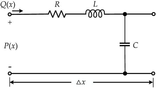
Figure 5. An infinitesimal section of a fluid transmission line.
2. Fading and Multipath Propagation
During the propagation of mud pulse signals in the drill pipeline, power loss occurs due to the viscous dissipation and friction of the borehole wall, which is influenced by various factors such as well depth, mud viscosity, mud density, signal frequency, drill pipeline diameter, the number of drill pipeline sections, and annular clearance [46,47].
The mud fluids have high viscosity, and when combined with other high-concentration leakage substances, they can cause significant signal energy attenuation under long-distance transmission conditions [3]. Moreover, different frequency ranges of the signal experience varying different attenuation degrees, with higher frequencies suffering more severe attenuation. Advanced MPT systems often use higher frequencies for data transmission, which can further exacerbate the signal attenuation [48,49]. High-frequency components are more attenuated than low-frequency components, causing different frequency components of the signal to propagate at different speeds, and the time-domain signal will be smeared, resulting in signal dispersion. Therefore, it is possible to lower the carrier frequency appropriately, reduce mud viscosity by raising the mud temperature [46] or injecting nitrogen, and employ more advanced signal processing techniques to mitigate signal attenuation and improve the SNR of the received signal.
Mud pulse signals experience reflections at the nodes of mud pipelines, vibration dampeners, mud pumps, and drill bit connections due to impedance mismatch caused by the change in pipeline diameter, material, and structure [48]. These different transmission line segments have different instantaneous impedances. When there is a significant change in instantaneous impedance, the signal propagates in different directions, with a portion continuing forward and a portion reflecting back as echoes, resulting in multipath propagation. In the drilling system, there are only a limited number of multipaths that have a great impact on mud signal transmission. If the multipaths with less energy are ignored, it can be considered that there are six effective multipaths in the typical multipath system depicted in Figure 6 [21]. Multipath propagation leads to asynchronous reception of symbols at the surface, causing ISI and severely degrading the quality of the received signal. Additionally, the superposition of the main wave and multiple echoes causes destructive interference [50], resulting in severe signal attenuation and a low SNR at the surface. Equalizers are commonly used to overcome multipath propagation and compensate for signal distortion, and they are a key technology in surface signal processing. They will be discussed in more detail later.
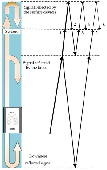
Figure 6. Reflection characteristics of mud pulse signal when the pipeline diameter of drill string changes.
3. Noise Analysis
Noise is generally considered to be anything other than the desired target information. Mud pulse signals are affected by a significant amount of noise during transmission in the communication channel. The amplitude of the noise is greater than that of the pulse signal, and its frequency spectrum partially overlaps with the signal, resulting in a low SNR of the transmitted signal. Therefore, separating the noise from the received signal and obtaining a high SNR signal becomes a challenging and crucial task in surface signal processing. Conducting thorough research on the types and characteristics of noise present in the channel helps in employing more accurate and scientific methods to filter out noise. To better study the impact of noise on the signal, special training sequences (TS) can be transmitted, and then the received waveform at the surface is compared with the transmitted waveform to estimate channel distortion [51].
Noise that affects mud pulse signals includes mud pump noise, reflection noise, bottom-hole mechanical vibrations, drill string vibrations, electromagnetic interference, pulse noise, and mud friction [52,53]. Among them, mud pump noise is the largest noise source. It is a periodic noise signal with a regular pattern, while other noises can be considered non-periodic random Gaussian white noise. Generally, the transmission model for mud pulse pressure waves can be described in Figure 7.
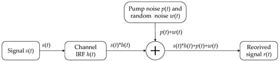
Figure 7. Schematic diagram of the MPT signal transmission model.
The data transmission formula can be described as follows:
 where s(t) is the original mud pulse signal, p(t) is the mud pump noise, w(t)is random Gaussian white noise, r(t) is the signal collected by the pressure sensor, h(t) is the impulse response function (IRF) of the channel, and * means convolution. The output result of the downhole signal via the channel is the convolution of the channel IRF h(t) and the signal s(t).
The mud pump is a device that provides power to the mud, and the pressure sensor on the surface is installed close to the mud pump, making the mud pump a strong noise source. When the mud pump operates under stable conditions, the pump noise is a relatively stable periodic signal, with a fundamental frequency that remains fixed and corresponds to the frequency of the mud flow discharged by the pump. Unfortunately, the operating state of the mud pump is often unstable, and therefore the pump noise is not entirely periodic. The pump noise includes the fundamental frequency component and multiple distinct harmonic components, and its spectrum is distributed in a comb shape. If the mud pump speed or the number of cylinders changes, the frequency of the pump noise will change accordingly. Mud pumps usually adopt reciprocating triplex pumps, the cyclic angular variation of the mud flow is 2π/3 [54]. Therefore, the mathematical model of mud pump noise can be simply regarded as a periodic signal composed of the superposition of three sinusoidal signals with different frequencies as follows [55]:

where different types of mud pump noise can be simulated by adjusting the coefficients a, b, and c.
However, there is currently no fixed and accurate mathematical model that describes the characteristics of mud pump noise. The pump stroke signal, which describes the parameter information of the reciprocating motion of the pump piston can be detected by using a pump stroke sensor [56]. Yang et al. [57] attempted to estimate the channel impulse response function of the pump stroke signal using the coherent accumulation method and established a Longuet-Higgins probability distribution for the pump stroke frequency to model the pump noise using statistical methods. Chen et al. [58] constructed three pump noise models applicable to ordinary n-cylinder mud pumps under normal operation: linear time-invariant, linear time-varying, and nonlinear models. The energy of the pump noise is relatively high, causing the mud pulse signal to be submerged in the pump noise. Therefore, the denoising of pump noise has always been a focus and challenge in surface signal processing. The other random Gaussian white noise has less energy and is easy to handle, so it will not be analyzed too much.
This entry is adapted from the peer-reviewed paper 10.3390/electronics12183930
This entry is offline, you can click here to edit this entry!