The integration of renewable energy sources (RES) as distributed generation units to the power grid has been accelerated by the rising demand for energy and the growing concern over the environmental effects of conventional sources. At the same time, modern electric vehicles (EV) are demonstrating a promising ability to decrease the consumption of fossil fuels. The issues related to a combination of various renewable energy sources to fulfil the load requirements can be solved by the application of multi-input–output architecture that is properly designed. In order to increase the driving range of EVs, several energy sources, including ultracapacitors and fuel cells, should be connected and operate in combination with a battery storage system. To manage these energy sources with various voltage-current characteristics, the same concept can be applied.
1. Introduction
The demand for renewable energy sources (RES) has been steadily rising in recent years. A dependable solution to the current global energy problem brought on by unstable political and economic conditions can be found in the production of electricity using diverse renewable energy sources, such as solar, hydro, wind, tidal, and biomass [
1]. Given the limited availability and high CO
2 emissions of conventional fossil fuels such as coal, natural gas, and oil, the importance of renewable energy sources is growing [
2]. Over the following decades, renewable energy sources will become the most important and fundamental components in achieving energy efficiency, energy savings, and environmental protection [
3].
The unpredictable zero-power periods brought on by different renewable energy sources, such as photovoltaics (PV) and wind turbines, can be reduced with the help of the hybridization of the system. As a result, the use of PV modules, energy storage (ES) batteries, and wind power production systems have a larger potential to provide continuous electrical energy than the use of only one renewable energy source [
4].
Although there have been great advancements in the use of renewable energy sources, there are still some substantial limitations. These limitations are a result of issues with voltage and frequency variance, grid protection, safety, and solidity of the system, as well as power quality.
The concept of microgrids (MG) is being developed as a solution to these problems in order to meet local energy demands while also enabling the connection of diverse renewable energy sources to the main distribution grid via nearby substations [
5,
6,
7]. Because they can interface renewable energy sources, DC loads, and the majority of energy storage systems, MGs are able to reduce the number of times when direct current (DC) is converted to alternate current (AC) and vice versa, thus increasing the system’s overall efficiency. The additional stages of energy conversion make the system more complex, increase energy losses, and reduce system efficiency in general [
8,
9].
It is required to use separate conversion stages for the load, energy storage systems, and renewable energy sources in order to allow power transfer between them, due to the fact that energy storage devices often have standard outputs that are different from the output of renewable energy sources based on their voltage-current characteristics. According to recent statistics, static power electronic converters are used to transport over 70% of electrical energy produced to the grid. Classical DC-DC converters such as the Boost, Buck, Buck-Boost, CUK, SEPIC, and ZETA require a significant number of components to provide adequate output voltages and integrate renewable energy sources into the microgrid [
10,
11]. It causes the end product to be expensive and the equipment to be complex. Therefore, integrating numerous ports using separate power converters is not an effective approach.
A different strategy was suggested as an alternative to creating a power converter with integrated numerous ports, or multiport converter (MPC). The multiport converter’s major objective is to connect several power sources with inputs and outputs through a single power converter to enable power flow between each port. These multiport converters are designed to remove redundant and superfluous power conversion stages and excessive semiconductor switching devices that would often be present in classical topologies. When compared with the benefits offered by multiport converters, using numerous conventional converters becomes less appealing, especially in hybrid systems that combine renewable energy sources, energy storage, the grid, and a variety of loads or consumers. In some cases, the multiport converters perform other important control functions in addition to regulating the low-level direct current voltages of the renewable energy sources to the proper level for supplying the inverter. Therefore, there are currently two main approaches, including the use of an individual converter for connecting each energy source to the grid or a multiport converter for connecting several sources that can be used to link various renewable energy sources, including the battery, to supply load or the grid.
Another field of multiport converters’ application is electric vehicles (EV). The automotive industry has a significant impact on the development of human civilization and the economy. Internal combustion engine (ICE) cars have a significant impact on pollution and carbon dioxide emission [
12]. Vehicles equipped with ICE account for 20–30% of overall emissions of greenhouse gases [
13]. As an alternative to ICE vehicles, electric vehicles emerged on the market [
14]. Electric vehicles are given more attention as a result of their replacement of ICE with an environmentally friendly option. Modern EVs have different energy sources such as batteries, ultracapacitors (UC), and fuel cells (FC). These energy sources require a reliable means of power transfer. Power delivery from energy sources is greatly aided by power electronic circuits. The DC-DC converter is essential for managing various energy sources and stabilizing DC buses, as was mentioned for the renewable energy systems [
15].
2. General Classification and Operation Principles
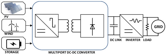
The multiport converter’s main objective is to integrate numerous power input nodes into a single device while still allowing power to flow between each node. A photovoltaic panel, a battery energy storage system (BES), a DC-DC converter used for multiple inputs, an inverter, and a load are the components of a two-stage multiport system shown in Figure 1. In addition, the multiport system is linked to the distribution grid.
Figure 1. Structure of a double stage MPC system connected to a distribution grid line.
The entire power flow expression for the multiport converter system in Figure 1 is as follows:
where:
PBES—is battery energy storage power, W
PPV—is solar power obtained by the photovoltaic panel, W
PWIND—is wind generated power, W
PLOAD—is the power corresponding to load demands of the local consumers, W
PGRID—is grid power, W
Depending on the power demands,
PGRID is either injected into the grid or withdrawn from it. As a result, grid power can have positive or negative signs based on the direction of power flow in the energy. Multiport converters, as was previously noted, provide some advantages over traditional converters [
24].
The multiport converter’s architecture helps to prevent the use of the communication bar and aids in achieving centralized control of the energy system [
31,
32]. In the literature, numerous topologies for multiport converters have been presented.
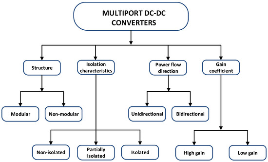
Figure 2 depicts the broad classification of multiport based on the selection criteria such as structure, isolation characteristics, power flow direction, and gain factor. In general, three major groupings can be used to classify the majority of the known and reported multiport converters based on the isolation characteristics:
-
Non-isolated multiport converters;
-
Fully isolated multiport converters;
-
Partially isolated converters.
Figure 2. General classification of multiport converters.
2.1. Non-Isolated Multiport Converters
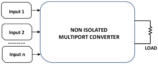
Each category of converters is explained in general terms, and the corresponding comparisons are made in the current section. The converters that do not provide electrical isolation between the input and output stages fall under the category of non-isolated multiport converters (Figure 3).
Figure 3. Structure of non-isolated n-port MPC system.
The input power ports share the same ground in a non-isolated multiport converter design. High power density, fewer switches, a relatively simple control scheme, and a compact design are a few benefits of non-isolated multiport converters. In addition, these types of MPCs not only help lower the overall cost but also achieve low electromagnetic interference (EMI).
In order to feed a household load ranging from 50 watts to 3500 watts, the research presented by authors in [
34] proposes a novel multi-stage non-isolated three-port converter with a 5H inverter where an additional semiconductor switch is connected to a conventional H bridge circuit. Both grid-connected and island power modes are supported by the proposed three-port converter. A description of a demand-side management algorithm with eight operational modes is also provided.
Another NI-TPC is proposed in [
36]. The use of a novel single-inductor non-isolated three-port converter in a photovoltaic fed DC microgrid with a battery storage system is suggested. Since two of the three ports can handle reversible currents, as opposed to one bi-directional port in existing NITPCs, a more flexible power flow can be obtained. The authors state that the developed NITPC can operate and switch between islanded mode and DC grid-connected mode without any issues.
2.2. Isolated Multiport Converters
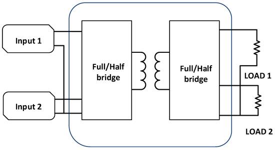
Galvanic isolation between the input and output stages is a typical feature of the isolated multiport converters, as shown in Figure 4.
Figure 4. Structure of isolated double-input-double-output (DIDO) port converter system.
Thanks to the pulse transformer’s turns ratio, it can also be used for buck and boost applications in addition to galvanic isolation. The isolated multiport converters’ primary feature is the use of separate windings for each power input. The fluxes of each main winding contribute to the voltages induced in the secondary winding. Isolated multiport converters are typically employed in RES and hybrid electric vehicle (HEV) applications. Isolated multiport converters have a number of benefits, such as less risk of electric shock, a wide range of voltage gain, noise filtering, and integration of various voltage ratings.
A novel isolated current-fed DC-DC boost type converter is suggested and developed in [
39]. The converter is using two input power sources based on a multi-transformer structure. This converter is suitable for the application of fuel cells and super-capacitors in a hybrid energy system. The proposed multiport converter can draw power from two different DC sources with lower voltage and send it separately or simultaneously to the higher voltage DC bus or load using a specific transformer windings connection technique.
2.3. Partially-Isolated Multiport Converters
The so-called partially isolated multiport converters represent a different category of multiport converters (Figure 5).
Figure 5. Structure of partially isolated double-input-double-output (DIDO) port system.
The single winding of the high-frequency transformer can be connected to the input power port of an isolated multiport converter. Connecting to the input ports’ common ground point is required. This converter’s topology can be described as a hybrid of fully isolated and non-isolated multiport topologies. High power density, adjustable voltage ranges, and galvanic isolation of the load from the primary side are only a few of the main benefits of partially isolated multiport converters.
2.4. Modular and Non-Modular Multiport Converters
The quick rise in demand for the integration of renewable energy with numerous applications is what brought attention to modular multiport converters. These multiport converters make it very simple to add or remove a new energy source with fewer components than in the case of the application of conventional converters. As shown in [
52], a modular multiport converter with a bidirectional port for battery charging applications (
Figure 6) consists of six ports, from which three ports are input and the other three ports are output. Using Matlab/Simulink environment, the proposed topology is simulated, and the output results are plotted. The authors also provide a report that shows output data and a hardware prototype of the system.
Figure 6. Structure of modular multiport system proposed.
A similar approach is used in [
53]. The proposed multiport converter with a modular structure is able to handle a number of sources and loads. A modular converter topology has been designed for usage in energy systems with multiple sources and multiple loads. The converter is based on a specific switching scheme, and this switching scheme has been used to examine the converter’s working principle. In continuous conduction mode (CCM) and discontinuous conduction mode (DCM), the converter’s steady-state operation has been described. It has been possible to identify and characterize many DCM modes. Studies on sensitivity analysis, loss and efficiency modeling, and dynamic characterization are also carried out.
For non-modular multiport topology, the extension can be performed with the help of incorporating the fundamental structures in series. Two novel bridge-type dual input DC-DC converter topologies for combining two input energy sources are presented in [
54]. The second topology is an upgraded version of the first of the two topologies. The load can receive power from the input energy sources concurrently from both converters.
2.5. High-Gain and Low-Gain Multiport Converters
An important aspect of classifying multiport converters is the gain factor. Based on an application-oriented strategy and the demands of high gain or low gain, multiport converters can be chosen. This is important for the transfer of electrical power from the hybrid system based on various energy sources to the load. Various techniques, including the use of standard interleaved and cascaded boost converters, can be employed to attain a high gain [
57,
58,
59]. The circuit’s cost and control complexity are raised as a result of the application of these topologies, though.
The high gain is essential in fields such as motor drives and renewable energy. To meet load requirements, these converters raise the low voltage from energy storage systems and renewable energy sources to high voltage. By raising the turns ratio in the high-frequency transformer, it is possible to achieve high gain in isolated multiport converters. In [
60] a multiport high-gain converter is proposed. The power source has one port, the battery has two ports, and the high voltage DC bus has three ports. In both boost/battery discharge and buck/battery charging modes, the operation of the converter is examined. The converter’s operation and in-depth theoretical analysis are presented. The proposed converter is capable of bidirectional and inter-source power transfer. A gain comparison with other converters is performed.
2.6. Bidirectional and Unidirectional Multiport Converters
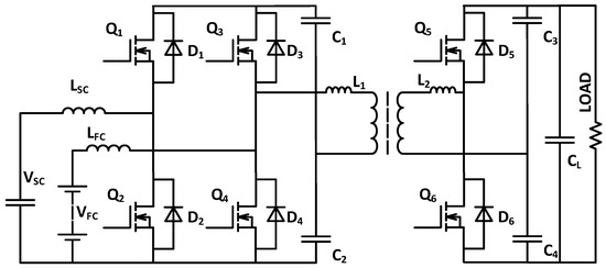
Applications for energy storage systems are driving the demand for multiport bidirectional converters. The power flow in these converters can pass either direction. These converters are mostly used in EV or HEV, including trains, nano and microgrids, and other types of electric drivetrain systems. The well-known isolated bidirectional converter is a dual active bridge (DAB).
In order to operate with a higher switching frequency, achieve a better power density, and improve the efficiency of the bidirectional converter authors in [
66] suggests a zero-voltage-transition (ZVT) three-level DC-DC converter. To test the converter operation mode, a 650 W prototype has been created. At a switching frequency of 200 kHz, it achieved the maximal efficiency of 95.5%.
The power flow in unidirectional types of multiport converters is only in one direction. The energy source can be used only to supply power to the load. These converters are widely used in renewable energy applications in the absence of energy storage systems. A bidirectional multiport converter can be developed by substituting unidirectional semiconductors with bidirectional ones.
3. Common Multiport Topologies
Figure 7, displays one of the earliest non-isolated multiport converter topologies recorded. Two typical boost converters are connected in series to form the topology [
70]. At that time, creating a new multiport topology by connecting two or more converters in series or parallel was typical practice. Numerous topologies of this kind were employed for the creation of independent power.
Figure 7. Topology of 3-port, 2-input boost multiport converter.
The following equation can be used to express the voltage on the output port that is linked to the load:
where δ1, δ2 are duty cycles for Q1, Q2 are respectively.
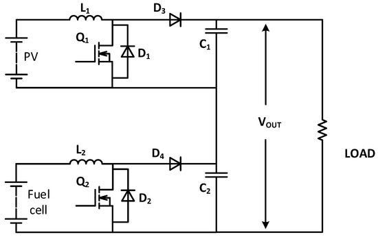
Figure 8, shows the partially isolated multiport converter, which combines direct and magnetic coupling. The converter was created specifically for application in combination with fuel cells [
71].
Figure 8. Topology of 3-port, 2-input boost multiport converter.
The six semiconductor switching devices used in the multiport converter (Q1–Q6). The application of a high-frequency transformer helps to isolate the output port from the input. While Q5 and Q6 form a bidirectional half-bridge for the output side, Q1 and Q2 together with Q3 and Q4 make two boost half-bridges.
The following equation represents the power flow to the converter’s load side:
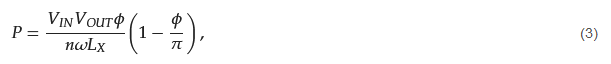
where
P—is the power flow from input to output side, W
VIN—is the input side DC voltage, V
VOUT—is the ouput side DC voltage, V
ω—is the angular frequency, rad/s
n—is the number of turns of the high-frequency transformer,
φ—is the phase shift angle between control signals, rad
LX—is the leakage inductance, H.
According to Equation (3), at a particular switching frequency, the phase shift angle and leakage inductance have a significant impact on the output power. This architecture was created for the integration of fuel cells.
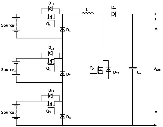
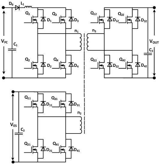
Figure 9, presents the topology of a fully isolated multiport converter. This topology is suggested in [
72,
73], and it is created as a modular system with three ports for each module.
Figure 9. Topology of three port fully isolated multiport converter.
The purpose of diode D0 in Figure 9 is to protect the fuel cell by preventing the flow of reverse current. Current ripples are filtered and softened by choke L1. Power flow in the system is regulated by the phase shift of the gate control signals for the active bridge that connects the fuel cell port and output ports.
4. Control Systems for Multiport Topologies
Control strategies are essential for multiport converters to achieve their maximum efficiency. This is because control techniques can make these converter topologies’ overall operations more efficient. Power flow management between ports of a multiport converter can be implemented using various control methods. The input voltage, duty cycle ratio, reference voltage, and output voltage are among the control parameters for MPCs. The operation of multiport converters can be controlled by taking into account these parameters. For the best control of multiport converters, the switching operation should fulfill the output requirements. Control techniques are performed while taking into account all possible scenarios.
he multi-input multi-output systems’ open-loop shaping is the basis for the controller design. The control design process consists of:
-
determination of a family of nonparametric models of the SIDO converter at operating points of interest;
-
determination of the class of the controller;
-
convex minimization of the summation of the square second norm of the errors between the system open-loop transfer function matrices and a desired open-loop transfer function matrix shapes the system’s open-loop transfer function.
The suggested multivariable controller shows satisfactory performance in the cross-regulation suppression of the output voltages of a SIDO converter, according to modeling and experimental results. The suggested approach is all-encompassing and adaptable to a SIMO converter for the various number of output voltages.
This entry is adapted from the peer-reviewed paper 10.3390/app13042579