Your browser does not fully support modern features. Please upgrade for a smoother experience.
Please note this is an old version of this entry, which may differ significantly from the current revision.
Subjects:
Energy & Fuels
Hydrogen carriers are one of the keys to the success of using hydrogen as an energy vector. Indeed, sustainable hydrogen production exploits the excess of renewable energy sources, after which temporary storage is required. The conventional approaches to hydrogen storage and transport are compressed hydrogen (CH2) and liquefied hydrogen (LH2), which require severe operating conditions related to pressure (300–700 bar) and temperature (T < −252 °C), respectively. To overcome these issues, which have hindered market penetration, several alternatives have been proposed in the last few decades.
- hydrogen carrier
- compressed hydrogen
- liquefied hydrogen
- ammonia
- methanol
1. Introduction
Hydrogen is an attractive energy vector due to its high gravimetric energy density (e.g., 120 MJ/kgH2 vs. 55.6 MJ/kgCH4 for methane), and the potentiality to make power production carbon-neutral. Nevertheless, its production is still highly dependent on fossil fuels and only 4% is derived from water electrolysis [1], and so relevant efforts are required in making hydrogen an energy carrier suitable for a sustainable green economy. In the last decades, researchers have focused on several kinds of water electrolyzers, such as polymer electrolytes membrane (PEMWEs) [2,3], alkaline water electrolyzers (AWE) [4,5], and solid oxide electrolyzers cells (SOEC) [6,7], which differ in component materials and operating conditions. Moreover, in green hydrogen production, electrolyzers must exploit the excess energy from the renewable energy sources (RES) grid, and then, in a reasonable scenario, hydrogen is not immediately used when produced, and so storage systems are required [8,9,10,11,12,13]. The hydrogen storage systems must display key features to be competitive with conventional fuels (gasoline, methane, liquid natural gas) and other energy storage systems (batteries). They must provide high safety standards, allow fast hydrogen release when required, and be economically sustainable. Moreover, with hydrogen being the lightest element, it has the intrinsic limitation of a low volumetric energy density under ambient conditions, thus introducing storage and transport issues.
Currently, the most common method of hydrogen storage is to pressurize the gas in high-pressure tanks (350–700 bar) [14,15]. The high pressure has the benefit of reducing the volume required, but the compression work required has a negative impact on the global energy balance, with a consumption equivalent to 11–13% of the energy contained in the stored H2 [16]. In addition, other technological issues are still unsolved, limiting the application of such an approach. The severe operating pressure places strong mechanical stress on the vessels, which are mainly made of steel or aluminium. As such, the shell must have a thickness able to tolerate the tension and meet safety requirements not only under conventional operating conditions, but also during undesirable events such as collisions [17]. The direct consequence is an increase in the weight of the hydrogen vessel, which strongly impacts the suitability of this methodology for mobile applications. Furthermore, molecular hydrogen can cause serious damage to infrastructure (metal tanks and pipelines) due to the activation of phenomena such as H2 embrittlement, which reduces the lifetime service of the structure itself [18,19]. Alternative materials such as carbon fiber reinforcements have been investigated for lighter vessels, preserving mechanical resistance, but despite the promising results, the material costs limit large-scale applications. Nevertheless, hydrogen storage at high pressures could be interesting for stationary applications, and for creating “hydrogen banks” able to store a high volume of hydrogen. This concept would exploit the possibility of storing an elevated amount of hydrogen in salt caverns. These are particularly favorable for this area due to their low permeability to H2, thus reducing gas leakages [20,21].
Hydrogen can be also stored in a liquid state, but this requires extremely low temperatures (−253 °C), which can be reached only by high energy-consuming cryogenic loops [22,23,24]. The keeping of such low temperatures consumes at least 30% of the stored energy, thus decreasing global efficiency [25,26]. On the other side, liquid storage operates at a lower pressure than gaseous, reducing the vessel weight and improving safety conditions. Nevertheless, the costs are still too high for widespread usage, and this method is suitable only for niche applications where the release of hydrogen occurs in a short time, based on relevant investments.
Lately, other alternatives have been developed for hydrogen storage; among them, liquid carriers such as ammonia [27,28,29], methanol [30,31,32] and formic acid [33,34], as well as systems based on more complex liquid organic hydrogen carriers (LOHC) [35,36,37] or solid materials such as metal hydrides, could play a relevant role in the near future. The interest in alternative hydrogen carriers has increased due to the possibility of their operating in milder conditions (pressure and temperature) than those required by CH2 and LH2.
2. Hydrogen Carriers Supply Chain: From Production to Hydrogen Release
In the last two decades, several alternatives have been proposed to overcome the severe conditions required to employ CH2 and LH2 technologies. The most promising approaches discussed in the following sections are based on the storage of hydrogen through the formation of chemical bonds in a more complex molecule: the hydrogen carrier. In Table 1, key physical features of the hydrogen carriers discussed in the next section are compared with hydrogen and methane. In this review, methane is not closely discussed as a next-generation hydrogen carrier, despite its large usage and the role that it can play during the current energy transition. Although the CO2 methanation reaction allows for the storage of hydrogen in methane by exploiting captured carbon dioxide, and it shows full compatibility with the energy infrastructure, methane storage requires severe conditions relating to temperature or pressure due to the physical properties of methane (boiling temperature −161.5 °C, volumetric energy density at ambient pressure 0.0378 MJ/L). Such intrinsic limitations have already been raised for pure hydrogen storage, and high-pressure or cryogenic loops are used as they are competitive with other possible energy vectors. These two approaches have a negative impact on process energy balance, justifying the interest in the development of energy carriers that can store hydrogen under milder conditions.
Table 1. Main physical characteristics of hydrogen, methane, and hydrogen carriers considered in this review.
| Carrier | Boling Temperature (°C) |
Flash Point Temperature (°C) |
Inflammability Range (Vol%) |
H2 Capacity (wt. %) | Volumetric Energy Density (MJ/L) |
|---|---|---|---|---|---|
| Hydrogen | −252.9 | Flammable gas |
4–75% | 100 | 0.0107 (amb. pressure) 2.757 (CH2 @ 350 bar) 4.712 (CH2 @ 700 bar) 8.506 (LH2 @ −253 °C) |
| Methane | −161.5 | −188 | 4.4–17% | 25 | 0.0378 (amb. pressure) 5.800 (150 bar) 9.200 (250 bar) 22.200 (−163 °C, 1 bar) |
| Ammonia | −33.4 | / | 15–33.6% | 17.8 | 12.700 (10 bar, −34 °C) |
| Methanol | 64.7 | 9.9 | 6–50% | 12.5 | 15.8 |
| Formic Acid | 100.8 | 69 | 18–51% | 4.3 | 7.2 |
| Benzene Cyclohexane |
80 81 |
−11 −18 |
1.2–8% 1.3–8.4% |
7.2 | 6.660 |
| Toluene Methylcyclohexane |
111 101 |
4 −6 |
1.1–7.1% 1.2–6.7% |
6.2 | 5.640 |
| Naphthalene Decalin |
218 185 |
80 57 |
0.9–5.9% 0.7–5.4% |
7.3 | 7.777 |
| Dibenzyltoluene Perhydrodibenzyltoluene | 390 287 |
212 | / | 6.2 | 6.786 |
| NaBH4 | / | / | / | 10.8 | 15.48 |
| MgH2 | / | / | / | 7.6 | 15.84 |
Independent of its chemical composition, a suitable hydrogen carrier must provide:
-
A sufficient hydrogen capacity (>5 wt. %);
-
Easy and environmentally friendly production process;
-
Not too harsh conditions and high stability during storage;
-
Easy and safe handling during transport;
-
Low energy consumption during hydrogen release;
-
Option to be recycled.
This list identifies the main features that characterize the supply chain of hydrogen carriers: production, storage and transport, and hydrogen release for final utilization. All these stages, sketched in Figure 1.
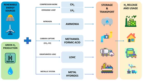
Figure 1. Schematic representation of the supply chain for hydrogen storage and carriers considered.
This entry is adapted from the peer-reviewed paper 10.3390/en16166035
This entry is offline, you can click here to edit this entry!