Your browser does not fully support modern features. Please upgrade for a smoother experience.
Please note this is an old version of this entry, which may differ significantly from the current revision.
Subjects:
Energy & Fuels
Energy storage systems (ESSs) are commonly used to shift the electric energy time and reduce operation costs by storing electrical energy during low-cost and excess power periods and injecting power during peak hours. Energy storage technologies have a wide range of applications in microgrids, including providing backup power and balancing the supply and demand of energy.
- assessment indices
- batteries
- energy access
- energy storage
- energy management
1. Introduction
At present, microgrids (MGs) and nanogrids (NGs) are becoming increasingly important in current power systems, due to several aspects, such as resilience, renewable energy integration, energy efficiency, cost savings, and energy access [1,2]. MGs and NGs are designed to operate independently or in parallel with the main power grid, providing a more resilient and reliable power source. This is particularly important in areas prone to power outages, natural disasters, or wars, as MGs can provide backup power and help maintain critical services. Also, they can integrate renewable energy sources (RESs) such as solar, hydropower, hydrogen, and wind power, reducing the reliance on fossil fuels and lowering greenhouse gas emissions [3]. They can be designed to optimize energy efficiency, using energy storage systems, smart grid technologies, and energy management systems (EMSs) to reduce energy waste and improve overall system performance. Moreover, MGs and NGs can reduce the cost of electricity for consumers by providing a more localized and efficient power source. They can also reduce the need for expensive infrastructure investments by utilities, such as transmission lines and substations. They can provide electricity access for communities not currently connected to the main power grid, such as rural areas or developing countries. Overall, MGs and NGs provide a more flexible, efficient, and resilient power system that can better meet the needs of consumers and communities. As such, they will become increasingly important in power systems as the demand for renewable energy, energy efficiency, and resilience grows.
Electrically speaking, the MG describes a small-scale power network that comprises a cluster of load centers, energy storage systems (ESSs), and distributed generators (DGs), whether RESs, micro-turbines, or diesel generators, operating together with an EMS, control units, and protection components. The purpose of MGs is to break up the massive traditional utility network into smaller, more manageable grids [4]. These smaller electrical networks can manage their DGs, load demands, storage systems, and protective devices. If each MG operates accurately and efficiently, then the utility grid as a whole can be correctly operated [5].
From a scale and complexity point of view, MGs, NGs, and picogrids (PGs) are all small-scale power systems designed to operate independently or in parallel with the main power grid. While they share some similarities, there are also some key differences between them. MGs are the largest of the three, and typically serve communities or small towns. MGs often incorporate advanced control systems and EMSs to optimize performance. NGs are smaller than MGs, and typically serve individual buildings or small clusters. They may consist of a single RES, such as a solar panel or a wind turbine, along with an ESS, and may be connected to the main grid or operate independently. NGs often incorporate smart grid technologies to optimize energy use and minimize waste. PGs are the smallest of the three, and typically serve individual homes or small businesses. They may consist of a single RES, such as a solar panel or a wind turbine, along with a small ESS. PGs are typically designed to operate independently of the main grid, providing a localized and reliable power source.
In summary, MGs, NGs, and PGs provide localized and reliable power sources but differ in scale and complexity. MGs are the largest and most complex, while NGs and PGs are smaller and more focused on individual buildings or homes.
ESSs are widely used in MGs for several purposes, as shown in Figure 5 [3,4]. ESSs are commonly used to shift the electric energy time and reduce operation costs by storing electrical energy during low-cost and excess power periods and injecting power during peak hours. ESSs help reduce the MG total operating cost, considering the time of charging and discharging and the fluctuating price of kWhs on the markets [7]. In MGs, the consumption is stochastic and unpredictable, which may affect the system’s stability. Some storage systems have a quick response time, and can be used to adapt to load changes and securely maintain MGs [8]. ESSs are also suitable for improving system reliability by avoiding unintentional interrupts and speeding up MG restoration time. Furthermore, they can be used to balance generation and load demands. ESSs help MGs avoid cascading failure by ensuring N-1 and N-2 security [9]. ESS can be used as a spinning reserve support for MGs, to cover energy shortages during unexpected and abnormal situations by storing extra power during off-peak periods and assisting the MG during uncounted interruptions [10]. Generally, low-inertia MGs are prone to frequency and voltage fluctuations, particularly in the presence of RESs. Quick-response ESSs are commonly preferred to mitigate this issue [11]. Many research studies recommend using ESSs to improve power quality [12,13,14], especially if RES is widely installed. They also play a vital role in increasing renewables’ hosting capacity (HC) [15,16].
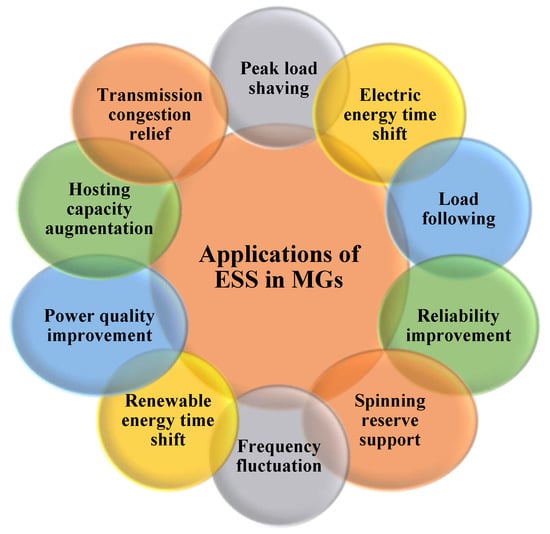
Figure 5. Applications of ESSs in MGs.
The output of RES is stochastic, and continuously varies during the day. For example, photovoltaic (PV) system output energy varies with changes in solar radiation and ambient temperature. The output energy of a wind turbine is affected by wind speed. The use of ESS is critical, particularly for isolated MGs, to firm RES capacity and provide a constant power supply in MGs [17]. Electric consumption steadily increases, which may cause congestion on the transmission lines. ESS can be installed near heavy loads to reduce power flow through power lines [18].
Moreover, due to the stochastic or intermittent nature of RESs, integrating RES into MGs may deteriorate the system’s reliability and threaten the MG’s stability. In order to achieve the optimal operation of an ESS-integrated MG, an EMS and an accurate forecasting algorithm must be integrated into the MG central controller to keep the MG secure and reduce reliance on the primary grid [19]. The EMS is the brain of MGs, and should meet both the long-term and short-term requirements. Many energy management optimization strategies have been presented in the literature [20]. They depend mainly on properly scheduling alternative energy resources or storage to preserve stability and optimally dispatching the generated power to maximize economic profits [21].
2. ESSs in Microgrids: Integration Strategies and Models
This section will explore the integration strategies of ESSs into MGs, and their design models.
2.1. Integration Strategies
As shown in Figure 7, ESSs are generally integrated into MGs through four configurations: distributed, aggregated, isolated, and grid-tied. In the distributed configuration, ESSs are placed in different locations in the MG, while in the aggregated configuration, all ESSs are placed in the same location. In the isolated configuration, ESSs are disconnected from the grid, whereas in the grid-tied configuration, the main grid is available, which promotes all the system inertia.
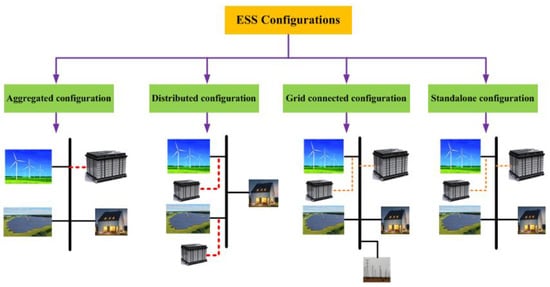
Figure 7. Configurations of ESSs in MGs.
For instance, in Hemeida et al. [83], a hybrid MG comprised of a PV system, a wind turbine, an ESS, and a diesel generator was introduced to meet load demands in Bernice, Egypt, a remote area on the Red Sea. Different configurations for the MG, such as a PV-battery configuration, wind-battery configuration, PV-wind-battery configuration, PV-battery-diesel configuration, wind-battery-diesel configuration, and PV-wind-battery-diesel configuration, were also suggested and analyzed. The goal of the design process was to optimize the cost of electricity, the renewable factor (RF), and the power supply’s loss probability.
Hemeida et al. [84] introduced an optimal design approach for a remote MG in Makadi Bay, Red Sea, Hurghada, Egypt, consisting of an aggregated ESS, a PV generation source, and a wind turbine. The load demand data, solar radiation, temperature, and wind speed were recorded for a year, and used to find the optimal configuration of the system. The results demonstrated that constructing a hybrid MG comprising a wind generation source, PV, and ESS is cheaper than building each individually. Jalilpoor et al. [68] described an approach for determining the optimal size and management of distributed ESSs integrated into shipboard power systems. The system comprised four conventional generation units, two wind turbines, and two ESS units. The objective was to minimize the power generated from fuel oil-based generation units, the greenhouse gas emissions, and the cost. In Al-Ghussain et al. [85], a techno-economic analysis of an MG consisting of a wind turbine and a PV system was performed using four configurations—no ESS, PHS only, HBS only, and a hybrid PHS and HBS. The results revealed that integrating PHS and HBS with the PV and wind energy sources increased the RES fraction.
A grid-tied MG consisting of a PV unit, an ESS, and electrical loads was suggested by Xie et al. [86] to verify the effectiveness of a proposed optimal sizing approach for a two-layer battery, taking into account the dispatch of a virtual ESS in a smart MG with a high PV penetration level. Sharma et al. [87] presented quasi-oppositional swine influenza model-based optimization with quarantine to reduce the total operation cost and optimize the size of a grid-tied MG, consisting of an aggregated Li-ion battery system, a wind turbine, a PV unit, a fuel cell, and a micro-turbine. In Sharma et al. [88], twelve suggested configurations of an MG with and without a grid-tied system for the rural community in India were studied in terms of the levelized cost of energy and total net present cost. Various generation sources were used, like a PV source, a wind turbine source, a hydropower source, and the main utility grid. The simulations showed that the hybrid configuration of a PV-wind-hydro-based utility grid-tied network was economically the best. Further, Yang et al. [89] investigated the fluctuation reduction problem of a grid-connected MG with a wind turbine and a battery ESS. The objective was to decrease the fluctuation of grid power by dynamically charging or discharging the battery ESS.
2.2. Integration Models
The key mathematical challenge in incorporating ESS into an MG is determining the optimal ESS size to prevent MG instability and collapse. The installation of ESS at a random or non-optimal size can result in increased costs, system losses, and increased ESS capacity. The MG sizing problem is commonly formulated as an optimization problem with single or multi objectives, and is subjected to a set of linear/non-linear constraints, as shown in Figure 8. Chen et al. [90] presented, for example, a method for the optimal allocation and economic assessment of ESS in MGs, based on net present value. It aimed to maximize the difference between the MG operating costs without ESS (𝐶𝑜𝑝𝑁𝑆) and with ESS (𝐶𝑜𝑝𝑆). Bahramirad et al. [91] provided a methodology for finding the appropriate size of an ESS in an MG when reliability criteria were considered. A larger ESS necessitates greater investment costs but reduces microgrid operational expenses. The problem’s goal was to reduce both the ESS investment cost and the MG operation cost. The power balancing constraints and ESS charging (𝑃𝑐ℎ) and discharging (𝑃𝑑𝑐ℎ) rating power and capacity (𝐸𝐸𝑆𝑆) constraints were considered. The reliability constraint was designed so that the expected load lost (ELL) did not exceed the maximum allowable limit (ELLmax).
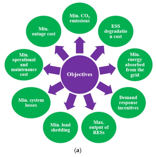
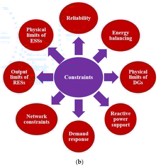
Figure 8. Energy management models (a) Objectives; (b) Constraints.
Sharma et al. [92] suggested that an ESS sizing model decreases the MG operating cost. The study considered the output power limits of DGs like wind turbines, PV systems, micro-turbines, and fuel cells. Furthermore, ESS limitations were modeled, and power grid constraints were used to limit grid sharing. In Xie et al. [93], the size of the ESS was determined based on the daily cost of the ESS. Besides the power generation limits, ESS constraints, and the power balance equation, the loss of power supply probability constraints were also considered. The value of losses in the MG was the main point in determining the required ESS capacity [94]. The current and voltage limitation equations were considered, to maintain the system’s thermal and voltage stability. Furthermore, the reactive power capability constraints were taken into account. In Liu et al. [95], the size of ESS was calculated so that the lifecycle cost of the MG was decreased. The time interrupt limit was considered. The load interrupt time should not exceed a specific period. Nojavan et al. [96] aimed to reduce the MG operating costs, besides minimizing the expected load loss. The minimum downtime and uptime of DGs were considered in the proposed model.
Furthermore, MGs use either an MG central controller to manage a decentralized layout or a centralized EMS to ensure that all devices operate optimally. Although an EMS is necessary for the operation of the MG, its deployment necessitates the resolution of control, communication, and timing problems. The EMS models are usually formulated as mixed-integer, linear, or non-linear optimization problems [97]. As shown in Figure 9a, the EMS commonly aims to minimize CO2 emissions, outage costs, ESS degradation costs, energy absorbed from the grid, operating and maintenance costs, system losses, and load shedding. In addition, the EMS aims to maximize the use of RES and control demand response programs. The EMS constraints can be categorized into reliability constraints, energy balancing constraints, physical limits of ESSs and DGs, reactive power support constraints, network constraints, RES constraints, and demand response constraints, as depicted in Figure 9b.
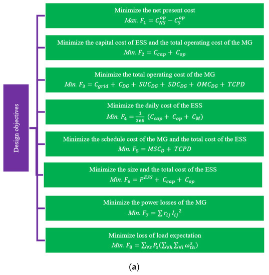
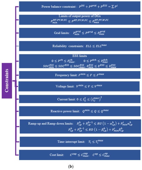
Figure 9. Sizing models (a) Objectives; (b) Constraints.
This entry is adapted from the peer-reviewed paper 10.3390/en16165930
This entry is offline, you can click here to edit this entry!