There has been an increase in the use of renewable energy resources, which has led to the need for large-scale Energy Storage units in the electric grid. Compressed Air Energy Storage (CAES) and Pumped Hydro Storage (PHES) are the main commercially available large-scale energy storage technologies. Among the in-development, large-scale Energy Storage Technologies, Pumped Thermal Electricity Storage (PTES), or Pumped Heat Energy Storage, stands out as the most promising due to its long cycle life, lack of geographical limitations, the absence of fossil fuel streams, and the possibility of integrating it with conventional fossil-fuel power plants. There have been a number of PTES systems proposed using different thermodynamic cycles, including the Brayton cycle, the Rankine cycle, and the transcritical Rankine cycle.
1. Introduction
Renewable sources of energy have become increasingly employed in recent years, in particular wind power and solar photovoltaic technology. The overall aim of this has been to decarbonise the energy sector. The International Energy Agency (IEA) reported that, in 2020, 29% of the electricity generated worldwide came from renewable sources [
1]. It is predicted that this percentage will rise to 49% by 2030 [
2]. One of the main drawbacks of renewable energy sources is that they are unable to supply power in a reliable and stable manner, as their sources are intermittent. This means that there is often a misalignment between the amount of energy being generated and the demand via the grid. One of the ways to mitigate this challenge is through the use of energy storage systems [
3].
They can offer large-scale energy storage and have a number of advantages: their operational lifetimes are long; energy losses are low during storage; they are not subject to the same geographic limitations; and they offer a high volumetric energy density [
4].
Pumped thermal energy storage (PTES) is a highly promising and emerging technology in the field of large-scale energy storage. In comparison to the other thermal energy storage technologies, this method offers high round-trip efficiency (RTE), high capacity, a life span of up to 30 years, as well as a short response time [
5,
6,
7]. Aside from being environmentally friendly and having a smaller carbon footprint, PTES systems have a fast startup time [
8,
9].
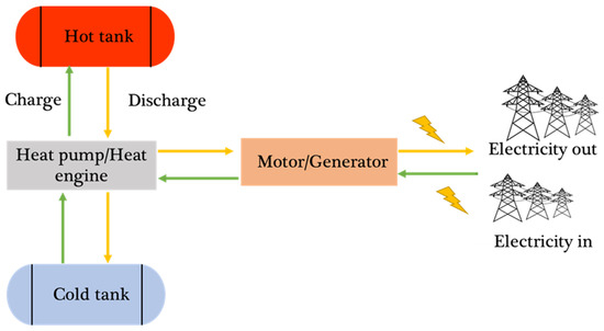
Electrical energy is stored in PTES as thermal energy. A heat pump uses electrical energy to move heat from a low-temperature reservoir to a high-temperature reservoir during the charging process. Various heat pump configurations are proposed [
10], and any heat pump technology could be used for the task. When the thermal reservoirs are discharged, the thermal reservoirs are used to power a heat engine, which converts the thermal energy back into electrical energy. The heat engine technology could be of any type, and different configurations have been proposed [
9,
11]. The conventional PTES layout is shown in
Figure 1.
Figure 1. PTES standard layout and main components, charging and discharging cycle.
The most significant losses occur during expansion and compression, as well as the heat transfer processes that are characteristic of heat pumps and heat engines. Considering this, current studies are being conducted to reduce such losses through the optimisation of components and operating conditions. Several PTES systems have been proposed over the past decade. Based on the thermodynamic cycle, PTES technology can be divided into two groups: (i) Joule–Brayton cycles, (ii) Rankine cycles [
9]. A packed-bed sensible heat storage system is commonly used for storing thermal energy [
10]. There have also been proposals to use latent heat storage, particularly for applications at low temperatures; furthermore, hybrid configurations of latent and sensible energy storage have been suggested [
7,
12,
13].
2. PTES Historical Background
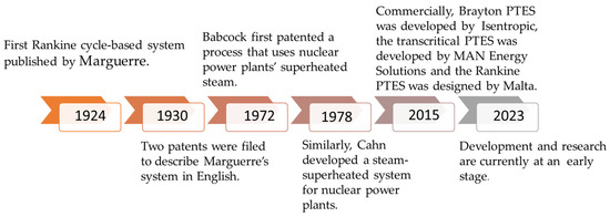
The concept of storing energy with a heat pump and the engine has been developed for several generations since Marguerre first introduced a system consisting of two Thermal Energy Storage Systems (TESs) filled with wet steam in 1924 [
14]. Two patents were filed in the 1930s that described Marguerre’s system in English [
15].
In 1972, Babcock [
16] first patented a process that uses nuclear power plants’ superheated steam. At 450 °C and 200 bars, a ceramic refractory accumulator was employed to compress and store the steam. A second early heat pump system was described in 1977 by Smith [
17]. In the process of charging, the air is compressed, cooled, and then liquefied. Regenerators or packed beds are used to store the energy extracted during cooling, while tanks are used to store the liquefied air produced by the process. An open supercritical system is discharged by the Rankine cycle; compressed liquid air is reheated in a regenerator and then expanded to produce work through a turbine. During the charging process, the cool air obtained from the process is stored in the cool store and used for the liquefaction process. Similar to Babcock’s approach, a system was developed by Cahn [
16] in 1978. Cahn proposed an energy system that could use thermal waste and would be independent of a power plant. In contrast to solid stores such as Babcock’s, the Cahn design does not have thermal fronts (a naturally unsteady phenomenon that reduces the maximum capacity utilisation of the tanks, and enhances self-discharge losses during storage, making the operation of the system relatively complex) and does not experience conductive losses.
The Highview Power system was developed between 2011 and 2014 and was a precursor to the LAES [
18], as described by Morgan et al. [
19]. However, there are some differences between these systems including: (i) compression–expansion processes (adiabatic or isothermal); (ii) liquefication processes (Claude cycle or Linde cycle); (iii) the number of compression and expansion phases; as well as the manner in which energy is recuperated. According to [
20], Highview Power’s prototype was only 8% efficient; this value is low due to the small size of the plant and the ineffective use of the regenerator.
Park et al. [
21] stated that the Highview design was constrained by pinch points that restricted the RTE (round-trip efficiency) to 36%. It is expected that further enhancements of

the system will result in efficiency levels that exceed 50%. Accordingly, LAES may be able to achieve similar efficiencies to other PTES systems and also have the advantages of using proven technologies, geographical flexibility, and abundant storage media [
21].
Joule–Brayton cycles and Rankine cycles have been used in recent studies to develop PTES systems. As part of the ISENTROPIC project, construction of a prototype based on a Joule–Brayton cycle began in 2015, while ABB is interested in building a prototype based on a Rankine cycle [
21]. In the commercial sector, a number of PTES solutions exist or are being developed. These include the Brayton PTES developed by Isentropic [
15], the transcritical PTES developed by MAN Energy Solutions [
22] and the Rankine PTES designed by Malta. While development and research are currently at an early stage, some controversial results regarding key performance indicators, such as round-trip efficiency, have been reported. There has been no systematic investigation of how thermal energy storage impacts system performance; studies are urgently needed to maximise the potential of PTES [
23]. The PTES development timeline is illustrated in
Figure 2.
Figure 2. PTES historical timeline.
3. PTES Thermodynamic Cycles
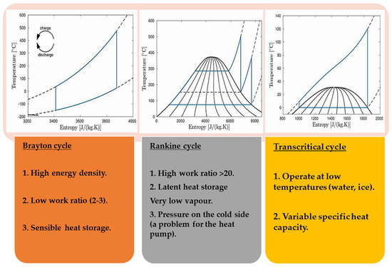
The PTES systems can be broadly categorized into three groups based on the type of cycle they incorporate. Within each category, several variations have been proposed, including Joule–Brayton cycles, Rankine cycles, and transcritical cycles. Figure 3 demonstrates the difference between the three types of PTES thermodynamic cycles.
Figure 3. Comparison between the common PTES thermodynamic cycles.
Table 1 below summarises and compares the three technologies (Brayton, Rankine and transcritical cycles).
Table 1. A comparison between the three PTES’s thermodynamic cycles (transcritical, Brayton and Rankine).
|
PTES Cycle
|
Working Fluid
|
Operating Temperatures
|
Advantages
|
Disadvantages
|
|
Brayton cycle
|
Air/Argon are commonly used
|
Hot storage: (500–1000) °C
Cold storage: as low as −70 °C
|
-
It is highly efficient at any temperature limit and pressure ratio.
-
Energy and power density are increased with a higher temperature ratio.
-
There is less friction loss in fluids.
-
Low emission.
|
-
The round-trip efficiency is highly dependent on turbomachinary efficiency.
-
Using low-grade heat integration to support PTES is also difficult due to the high temperature requirements.
-
High cost associated with high requirements and design.
-
A large air heater is required.
|
|
Rankine cycle
|
Thermal oil/pressurised water are commonly used
|
Operate at low temperature (100–250) °C
|
-
Widely available and cheap.
-
Low friction losses (low viscosity).
-
Less material requirements (chemical stable).
-
High heat capacity (excellent medium for heat transfer).
-
Heat pump cycles with lower cycle temperatures reduce thermal losses and maximise efficiency by incorporating low-grade waste heat with the classical cycle.
|
-
Big insulation needed (turbine, condenser), high specific volume and very low pressure due to low condensation temperature.
-
Efficiency loss and limited suitability to waste heat recovery
-
Expensive multistage turbine needed.
|
|
Transcritical cycle
|
CO2
|
Around 31 °C
|
-
Good match with heat source profile.
-
High exergy efficiency.
-
Environmentally friendly.
-
Inexpensive and nontoxic working fluid (CO2)
|
|
4. Analysis and Performance Enhancement of PTES
Recently, several PTES systems have been presented using a variety of thermodynamic cycles, including Joule–Brayton and Rankine [
32]. Currently, a variety of plant configurations have been studied for Brayton-based PTES, comprehensive thermodynamic analyses have been undertaken, and performance has been evaluated under various operating conditions [
9]. A study done by Guo et al. [
65] examined the effects of the design solution on key performance indicators, such as cycle temperatures and pressure ratios, and identified an optimal design of a Brayton-based PTES configuration. In spite of this, McTigue et al. [
24] concluded that round-trip efficiency is highly dependent on losses incurred during compression and expansion.
Exergy analysis conducted by Zhao et al. [
66] indicated that the expander discharge caused the greatest amount of exergy loss. In addition, advanced exergy analysis indicated that cold heat exchangers during discharge account for a significant portion of avoidable exergy destruction (95%) among the system components studied. Wang et al. [
29] analysed the PTES performance such as the effects of the heat transfer and the thermodynamics processes. A number of key factors in the design of TES systems, for example, aspect ratio and particle size, among others, are crucial for ensuring a stable discharging power and optimum round-trip efficiency. PTES performance has been investigated in this regard by Wang et al. [
67], who examined TES arrangements based on the number and mode of reservoirs and operating modes. As a result of their findings, the operational modes significantly impact on the variation ratio of delivery power, and the round-trip efficiency of the system, while the tanks count has an insignificant influence. Previous studies have focused on sensible packed-bed heat storage systems using argon as the working fluid in the TES section. A number of other gases have also been studied, including helium, carbon dioxide, and air [
28].
Dumont et al. [
68] reported that academics frequently report round-trip efficiencies of approximately 60% to 70%; however, such levels of efficiency can only be conducted by extremely large polytropic efficiency rates of turbines and compressors, which are typically greater than 90%. Due to the fact that the Brayton-PTES system’s efficiency is greatly impacted by polytropic efficiency, assuming slightly lower polytropic efficiency would result in a significant reduction in round-trip efficiency. Therefore, various innovative solutions should be examined to enhance the competitiveness of such storage systems. A [
15] suggestion was made to incorporate an electrical heater after the compressor, in order to convert electrical energy into thermal energy, which would enable the maximum cycle temperature to be independent of the pressure ratio of the compressor. The study demonstrated that despite a reduction in round-trip efficiency due to an electric heater, the cost of PTES could be reduced by reducing the heat exchange area and compressor size.
Zhang et al. [
69] investigated the potential of a PTES system as a power and cooling/heating system. Based on their findings, active and appropriate heat delivery through the hot tank could significantly enhance the outlet’s temperature stability during the working fluid’s discharging phase, thereby improving the system’s power delivery stability and electrical efficiency. According to Dumont et al. [
68], thermal integration can significantly reduce electricity losses when combined with other systems. Accordingly, Jockenhofer et al. [
13] investigated the impact of adding additional heat sources to PTES systems in terms of enhancing the round-trip efficiency and the exergy efficiency of the system. According to Wang et al. [
55], LNG cold energy may be able to be used as a heat sink for the PTES and a natural gas distribution system. The authors confirmed that thermal integration is feasible, as is the potential for enhancement of round-trip efficiency.
A Brayton cycle-based PTES system may also be suitable for integration into concentrated CSP. Solar energy can be captured and converted into electricity through a CSP system; however, solar radiation is intermittent, thus limiting the capacity factor. The integration of CSP plants with PTES systems may provide a solution to this limitation: Petrollese et al. [
7] presented and evaluated a novel PTES system integrated with a CSP. As part of this system, the same working fluid (argon) is used as in the CSP, and several components can be operated simultaneously or independently. TES consists of three thermocline packed-bed tanks. During this study, the performance of a PTES-CSP plant integrated with TES tanks was modelled in MATLAB using specific mathematical models under nominal conditions. A study was conducted to investigate the impact of the key design parameters of TES systems (e.g., the operating temperatures and pressure ratio) on the key performance indicators. A pressure ratio of about 5:2 was found to be optimal for the integrated plant’s exergetic round-trip efficiency. From this, an efficient PTES-CSP system with an exergetic round-trip efficiency of approximately 60% has been developed [
7].
5. Summary of Literature Review PTES
Recent research has focused on using PTES systems for power density applications. Table 2 and Table 3 summarise the various PTES systems described in the literature.
Table 2. A summary of the Joule–Brayton cycle studies in the literature.
Table 3. A summary of the transcritical Rankine cycle studies in the literature.
|
Efficiency [%]
|
HTF
|
Thermal Energy Store
|
Reference
|
|
ƞ RTE = 65 1;
ƞ RTE = 51 2
|
CO2
|
Storage tanks (ice, hot water)
|
[39]
|
|
ƞ RTE = (48–64)
|
CO2
|
Storage tanks (ice, hot water)
|
[48,49,87]
|
|
ƞ RTE = (65–73)
|
CO2
|
Storage tanks (ice, hot water)
|
[35]
|
|
ƞ RTE = 30
|
CO2
|
Storage tanks (water)
|
[88]
|
|
ƞ RTE = (43–56)
|
CO2
|
Phase-change materials and grounded heat storage
|
[54,89]
|
|
ƞ RTE = (52–66)
|
CO2
|
Hot thermal energy storage (tube-in-concrete)
|
[89,90,91,92]
|
|
ƞ RTE = 139
|
CO2/NH3
|
Heat exchanger and storage tanks
|
[55]
|
|
ƞ RTE = 58
|
R13I1 and CO2
|
Storage tanks (oils and water)
|
[46]
|
1 Commercial plant; 2 Pilot plants.
This entry is adapted from the peer-reviewed paper 10.3390/thermo3030024