Image-Based Fault Monitoring in Additive Manufacturing: History
Please note this is an old version of this entry, which may differ significantly from the current revision.
Contributor: , , ,

Fault monitoring in AM refers to the systematic process of monitoring and detecting deviations, anomalies, or faults during printing to ensure the printed parts’ quality, integrity, and reliability. It involves continuously monitoring the AM process’s critical parameters, variables, or characteristics and comparing them against predetermined thresholds or expected values. The goal is to identify and address any faults or anomalies that may compromise the final part’s quality or performance. It involves using various techniques, such as in-process monitoring, real-time data analysis, and automated systems, to identify faults or deviations from desired specifications. By monitoring parameters such as temperature, pressure, laser power, material flow, layer deposition, or surface quality, fault monitoring allows for the early detection of defects, material inconsistencies, structural irregularities, or printing errors.

  • additive manufacturing
  • fault monitoring
  • image-based
  • image acquisition
  • preprocessing
  • image analysis
  • defect identification

1. Introduction

The use of additive manufacturing (AM) in various manufacturing fields is expanding quickly due to its ability to create parts with complex features. It is a process of developing physical objects from a geometrical representation by fusing materials in discrete planar layers, but non-planar processes also exist [1]. Other terminologies used to describe AM processes include 3D printing (3DP), rapid prototyping (RP), direct digital manufacturing (DDM), rapid manufacturing (RM), and solid freeform fabrication (SFF) [2]. The whole AM process involves 3D computer-aided design (CAD) models to build parts in a layer-wise pattern. Some examples of software that create CAD are SolidWorks, Inventor, Google SketchUp, and Autodesk Revit [3]. Materials used in AM include metals and alloys, ceramics, polymers, composites, smart materials, concrete, and biomaterials [4]. Overall, this process allows individuals to fabricate structures with complex geometric parts that cannot be achieved through traditional methods [5][6][7]. Consequently, it caused a paradigm shift in product design and manufacturing [8].
The 1984 invention of 3D printers by Charles Hull has the potential to revolutionize industries and alter the production line. Over the years, this technology has experienced a phenomenal expansion [9]. AM has applications in electronics, electrochemistry and energy storage, catalysts, thermal management, aerospace, healthcare monitoring, food, sensors, and robotics. For example, AM is used in medical modeling for clinician training and clinician preparation, such as impact planning and pre- and post-operative planning. AM enables surgeons to create operative models for planning and surgical simulations by using imaging datasets as the geometric definitions to model 3D shapes by a variety of software for specific applications. The models are useful for education, but they can also be used to describe risky and difficult surgical procedures to patients and their families [10]. In construction, AM is used to enable automation. Doing so can lower labor for safety reasons, reduce construction onsite, reduce production costs, address sustainability issues, and increase architectural freedom [3]. In general, freedom of design, mass customization, waste minimization, fast prototyping, and the ability to manufacture complex structures are the main benefits of AM [11]. In addition, compared to conventional manufacturing techniques, AM has more controllable process parameters and more vital interaction between the material properties and process parameters [2].
The AM process involves three main phases: (1) the preprocessing phase, (2) the manufacturing phase, and (3) the post-processing phase. Each of these phases is further divided into sub-phases. Several phases, especially post-processing, depend on which AM technology is used. The preprocessing phase has two sub-phases: 3D model creation and data preparation. The 3D model creation sub-phase involves the creation of a 3D model of the object using CAD software or a 3D object scanner. Generally, the data preparation sub-phase converts a CAD model into a format for data handling in AM such as the standard tessellation language (STL) file. This file is then processed by a slicer program, which creates a job file that is saved in the format for the specifically designed machine. Furthermore, the manufacturing phase has two sub-phases: machine setup and building. During the machine setup, the material that will be used is loaded, and the process parameters in the printer are set. Afterward, the printer builds the model by depositing material layer by layer (building sub-phase). Lastly, the post-processing phase identifies the following sub-phases: part removal, support structures, heat treatment, shot-peening, and finishing [12].
The most popular way to classify AM processes is based on the product formation method. According to the American Society for Testing and Materials (ASTM F42), AM processes can be classified into seven categories, namely, material jetting (a drop by drop of build material is selectively deposited), binder jetting (a liquid binding agent is selectively deposited to join powder particles), vat photopolymerization (curing of photo-reactive polymers by the use of a laser, light or ultraviolet), powder bed fusion (uses an electron beam or laser to melt or fuse the material powder), material extrusion (material is extruded through a heated nozzle), energy deposition (similar to material extrusion but the nozzle is not fixed to a specific axis and can move in multiple directions), and sheet lamination (sheets of materials are bonded together to produce a part of the object) [7][13]. Table 1 shows an updated comprehensive overview of the advantages and drawbacks of each process [14][15][16]. Furthermore, these processes are subdivided into a few more related AM technologies. Another way to classify AM technologies is by the type of material used and the medium used for its processing (laser beam, ultraviolet rays, thermal means). Three main types of materials are used in AM: liquid-based, solid-based, and powder-based, as shown in Figure 1 [17]. Other ways to classify AM process are the material preparation, layer generation technique, phase change phenomenon, material type, and application requirements [2].
Figure 1. The AM process can be classified in many ways. One of which is the classification based on materials used: liquid, solid, and powder.
Table 1. The seven AM processes, according to ASTM F42, with their advantages, drawbacks, and related AM technologies.
The Seven AM Processes
AM Process Advantages Drawbacks Related Technologies
Material Jetting High accuracyLow wasteMultiple material parts and colors under one process Support often requiredLimited materialsNozzle blockage is commonLow viscosity and strength NanoParticle Jetting (NPJ)Drop On Demand (DOD)
Binder Jetting Different colorsHigh range of materialsFast processAllows two materials Not always suitable for structural parts due to the use of binder materialLong time post-processingHigh porosity, low surface quality Powder Bed and Inkjet Head (PBIH)Plaster-Based 3D Printing (PB3D)
Vat Photopolymerization High level of accuracy and good finishAllows transparent materialRelatively quick processTypically, large build areas Relatively expensiveLong post-processing timeLimited materialsRequires support structures Stereolithography (SLA)Digital Light Processing (DLP)Continuous Liquid Interface Production (CLIP)Daylight Polymer Printing (DPP)
Powder Bed Fusion Relatively inexpensiveAbility to integrate technology into small scaleLarge material optionsWide range of materials Relatively slow speedLack of structural properties in materialsSize limitationsHigh power usageFinish dependent on powder grain sizeThermal stress and degradation is common Selective Laser Sintering (SLS)Selective Laser Melting (SLM)Electron Beam Melting (EBM)Multi Jet Fusion (MJF)Direct Metal Laser Sintering (DMLS)
Material Extrusion Widespread, inexpensiveGood material propertiesLow material wasteFairly high fabrication speed Nozzle radius limitedLow accuracy and speedRequired constant pressure of materialDelamination is common Fused Deposition Modeling (FDM)Fused Filament Fabrication (FFF)
Energy Deposition High quality, functional partsSpeed often sacrificed for high accuracy May require post-processing for desired effectLimited materialThermal stress, requirement for atmosphere control Laser Engineering Net Shape (LENS),Electron Beam Additive Manufacturing (EBAM)Laser Deposition Modeling (LDM)Wire Arc Additive Manufacturing (WAAM)
Sheet Lamination High speed, low costEase of material handling Shrinkage, significant amount of wasteDelamination is common Laminated Object Manufacturing (LOM)
Despite the advantages of AM, such as design freedom, customization, waste reduction, and the ability to print complex structures, a few disadvantages require additional research and technological development. These particular difficulties include porosity brought on by inadequate material fusion, the anisotropic nature of the materials, and warping due to residual stress brought on by the rapid cooling nature of AM processes. Cracks, delamination, distortion, rough surfaces, lack of fusion, porosity, foreign inclusions, and process instability (keyhole, balling) are specific processing-related faults or defects in AM. These faults are frequently the result of the layer-by-layer material deposition process. In this process, some faults may propagate from one layer to the subsequent layers, causing the entire build to fail [18]. These faults become the cause for high costs and limited applications in large structures and mass production in AM.
The AM output is affected by various essential parameters, including layer thickness, printing speed, printing temperature, and material properties. A detailed understanding of the AM process—from the ability of materials to be processed to the relationship between the process–structure–properties of the AM parts—is crucial to ensure high product quality [5][8][18]. The first step in mitigating faults in AM is understanding the defects and their causes. Listed below are some of the common faults and their definitions. These can be categorized according to how AM affects the by-product, e.g., whether it affects the geometry and dimensions, surface quality, microstructure, or mechanical properties as shown in Figure 2 [19].
Figure 2. The common errors or faults in AM can be categorized in four ways, according to how it affects the by-product.
  • Geometrical Inaccuracy: the deviation of a printed object’s shape or geometry from its intended design due to issues in the printing process, such as incorrect bed leveling, insufficient cooling, or buildup of residual stress [20].
  • Warping: occurs when the edges of a printed object curl up or lift from the print bed due to uneven cooling, poor adhesion to the bed, low bed temperature, or residual thermal strain accumulated during the printing [21].
  • Balling: occurs when excess material collects and forms a ball or blob on the printed object during the printing process [22].
  • Splatter: the unintentional extrusion of material during printing, resulting in excess material or a messy print [23].
  • Anisotropy the variation in the mechanical or physical properties of a printed object in different directions, resulting from the layered nature of 3D printing [24].
  • Porosity: the presence of voids or holes within a printed object, which can result from incomplete or insufficient printing [25].
  • Cracking: occurs when a printed object develops cracks or fractures due to sudden changes in temperature during printing or other issues [25].
  • Delamination: the separation or detachment of layers in a printed object due to poor adhesion between layers caused by the improper gap between the nozzle height and print [21].
  • Over-Extrusion and Under-Extrusion: Over-extrusion occurs when the 3D printer deposits more material than necessary for each layer of the printed object. On the other hand, under-extrusion occurs when the 3D printer does not deposit enough material for each layer, resulting in incomplete or weak prints. It is caused by too much or a lack of filament flow, respectively [26].
One approach to fault monitoring is image-based fault monitoring. During printing, image-based fault monitoring in AM involves capturing visual data using cameras or imaging systems to analyze and detect faults or defects. Using computer vision techniques, this method analyzes captured images or videos and extracts relevant information for fault detection. Image-based monitoring focuses on the visual aspects of the printed part and its printing process, providing valuable information regarding surface quality, layer deposition, feature accuracy, and overall print integrity [27][28]. In image-based fault monitoring, captured images or video frames are examined for irregularities, deviations, or anomalies that may indicate printing defects. Combining multiple techniques, such as using different imaging modalities (e.g., visible light, infrared, X-ray) or employing advanced ML algorithms for automated defect classification, can improve image-based fault detection. The goal is to accurately and efficiently identify defects, ensuring high-quality and reliable AM outcomes. The images can also be used to inspect the surface quality of the printed part, detecting surface defects, warping, or roughness. Additionally, image-based monitoring can detect and analyze specific features or geometries on the printed part to ensure accurate reproduction. By continuously analyzing the visual data in real time, image-based fault monitoring enables operators or quality control personnel to identify and address faults early in the printing process, reducing the risk of producing defective or non-conforming parts [8][29]. Figure 3 illustrates the process of image-based fault monitoring in AM. Each step is further discussed in the following [30].
Figure 3. The image-based fault detection process is divided into five main steps: image acquisition, preprocessing, image analysis, defect identification, real-time monitoring and analysis, and decision making and quality control.

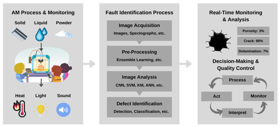
2. Image Acquisition

High-resolution cameras or imaging systems capture images of the manufactured parts at various stages of the AM process. These images can be obtained either during the printing process or after its completion. In this step, cameras are strategically positioned to capture the printing area or specific regions of interest. The number and placement of cameras depend on factors such as the size of the printing setup, the complexity of the part, and the desired level of coverage. Multiple cameras may provide different views or angles for comprehensive monitoring. The camera settings and parameters are configured to optimize image acquisition. This includes adjusting parameters such as exposure time, aperture, ISO sensitivity, white balance, focus, and frame rate. These settings are adjusted to ensure clear and correctly exposed images or video frames [31].
The images are captured at appropriate intervals based on the specific requirements of the AM process. Factors including layer deposition time, cooling periods, or critical stages of the printing process can determine this. The camera is also calibrated to ensure accurate and reliable measurements from the captured images. This involves determining the camera’s intrinsic parameters, such as focal length, lens distortion, and pixel size. It helps correct geometric distortions and ensure accurate measurements in subsequent image analysis steps. Two types of cameras are used in image acquisition, namely, optical and thermal.

2.1. Optical Camera

Optical cameras capture images within the visible light spectrum. These cameras function similarly to conventional cameras and can capture images with high resolution and color accuracy. Versatile and widely used in AM for monitoring the printing process and detecting visible flaws or inconsistencies, they are adaptable and versatile. Optical cameras can provide visual data on the printed object, such as layer deposition, surface quality, and geometry. They can capture images of each layer or specific regions of interest, enabling real-time monitoring and detection of flaws such as surface roughness, delamination, warping, or missing layers. Optical cameras are beneficial for detecting visible anomalies that may compromise the printed part’s structural integrity or final quality.
Other notable types of optical cameras are high-speed cameras, charge-coupled device (CCD) cameras, and complementary metal oxide semiconductor (CMOS) cameras. High-speed cameras capture images at a rapid frame rate, allowing for the detection of fast dynamic events during the printing process. These cameras can capture fine details and be used to monitor the deposition of each layer or detect defects in real time. CCD cameras offer several advantages regarding image quality, sensitivity, and dynamic range. They can capture high-resolution images with low noise, making them suitable for detailed imaging and analysis. CCD cameras are often used in scientific and industrial applications where image quality and accuracy are crucial [32]. CMOS cameras, on the other hand, have become popular alternatives to CCD cameras due to their lower power consumption, faster readout speeds, and cost-effectiveness. CMOS cameras are also widely used in AM and often provide comparable image quality [31].

2.2. Thermographic Camera

Thermographic cameras, also called infrared cameras, capture images based on objects’ heat or thermal radiation. These cameras operate in the non-visible infrared spectrum and are sensitive to temperature differences. By detecting variations in thermal patterns, thermographic cameras can identify areas of heat generation or dissipation, enabling the detection of thermal anomalies during the AM process [33]. Thermographic cameras help monitor AM-related issues, such as overheating, cooling inconsistencies, or thermal gradients. These anomalies may indicate faults such as improper material fusion, insufficient cooling, or insufficient energy input. By detecting these thermal irregularities, thermographic cameras can help ensure the integrity and quality of the printed part.

3. Preprocessing

The acquired images may undergo preprocessing steps to enhance the quality and extract relevant information [34]. Preprocessing aims to improve the clarity and consistency of the images for subsequent analysis. This includes steps such as image cleaning to remove unwanted artifacts, image filtering to reduce noise, contrast enhancement to improve the visibility of details, image registration to align multiple views, calibration to correct geometric distortions, image resampling for specific requirements, illumination correction to equalize lighting conditions, and image segmentation to isolate relevant regions or objects. These preprocessing steps ensure the captured images are high quality, free from disturbances, and adequately prepared for subsequent fault detection and analysis. This enables accurate and reliable identification of faults or defects in the AM process.

4. Image Analysis

Image analysis techniques are then applied to examine the preprocessed images. This involves extracting meaningful features from the images that can be used to identify defects. Different methods may be employed, including:
  • Image segmentation: This process involves partitioning the image into meaningful regions or objects. It separates the defects from the background or surrounding structures, making them easier to analyze separately [35].
  • Feature extraction: Relevant features are extracted from the segmented regions or the entire image. These features can include geometric characteristics (e.g., shape, size, or aspect ratio), texture patterns, intensity profiles, or statistical measures [36][37].
  • Classification: ML algorithms or pattern recognition techniques can classify the extracted features and distinguish between normal and defective parts. This may involve training a classifier on labeled data, where the defects are identified and associated with specific feature patterns [31].

5. Defect Identification

After classifying the features, the presence and type of defects can be determined. Surface irregularities, cracks, voids, porosity, warping, and other flaws may constitute defects. The analysis can provide information regarding the defects’ location, size, severity, and nature. Listed below are the steps involved in the process of identifying defects:
  • Fault localization: The first step in defect identification is to determine the precise location of the detected fault within the captured images or video frames. This involves mapping the identified features or anomalies to the corresponding regions of the AM process. Localization helps pinpoint the specific area where the fault or defect has occurred [31].
  • Categorization and classification: Once the fault is localized, it is categorized and classified based on its nature and characteristics. This step involves assigning a specific category or type to the detected fault, such as missing layers, surface irregularities, dimensional deviations, or structural defects. Classification helps understand the fault’s nature and facilitates subsequent analysis and decision making [31].
  • Severity assessment: The severity of the detected fault is assessed to determine its impact on the quality and functionality of the printed part. This involves evaluating the extent of the defect, its potential to compromise structural integrity, or its effect on critical dimensions or functional properties. Severity assessment helps prioritize the detected faults and guides subsequent actions for mitigation or correction.
  • Reference comparison: In some cases, a reference comparison is performed to assess the detected fault against a known reference standard. This involves comparing the features or characteristics of the faulty part with those of a defect-free reference part or an ideal model. Reference comparison provides a basis for evaluating deviations or abnormalities and determining the acceptability of the printed part.

6. Real-Time Monitoring and Decision Making

The defect detection and classification process is performed in real time as new images are acquired during the AM process. The system continuously monitors the images and provides immediate feedback on defects or anomalies. Real-time monitoring allows for timely intervention and adjustment of the manufacturing process to prevent further defects. The system generates alerts or notifications to inform the operators or control systems based on the detected defects or anomalies [38]. The alerts can trigger actions such as pausing the process, adjusting parameters, or initiating corrective measures. The decision-making process relies on predefined criteria or quality standards to determine the acceptability of the manufactured part. Data collected, including images, extracted features, and defect classifications, can be logged for further analysis and quality control. These data can be used for process optimization, defect trend analysis, and continuous improvement of the AM process.

This entry is adapted from the peer-reviewed paper 10.3390/s23156821

References

  1. Ahlers, D.; Wasserfall, F.; Hendrich, N.; Zhang, J. 3D printing of nonplanar layers for smooth surface generation. In Proceedings of the 2019 IEEE 15th International Conference on Automation Science and Engineering (CASE), Vancouver, BC, Canada, 22–26 August 2019; pp. 1737–1743.
  2. Abdulhameed, O.; Al-Ahmari, A.; Ameen, W.; Mian, S.H. Additive manufacturing: Challenges, trends, and applications. Adv. Mech. Eng. 2019, 11, 1687814018822880.
  3. El-Sayegh, S.; Romdhane, L.; Manjikian, S. A critical review of 3D printing in construction: Benefits, challenges, and risks. Arch. Civ. Mech. Eng. 2020, 20, 34.
  4. Ranjan, R.; Kumar, D.; Kundu, M.; Moi, S.C. A critical review on Classification of materials used in 3D printing process. Mater. Today Proc. 2022, 61, 43–49.
  5. Mahmood, M.A.; Visan, A.I.; Ristoscu, C.; Mihailescu, I.N. Artificial Neural Network Algorithms for 3D Printing. Materials 2020, 14, 163.
  6. Valizadeh, M.; Wolff, S.J. Convolutional Neural Network applications in additive manufacturing: A review. Adv. Ind. Manuf. Eng. 2022, 4, 100072.
  7. Shahrubudin, N.; Lee, T.; Ramlan, R. An Overview on 3D Printing Technology: Technological, Materials, and Applications. Procedia Manuf. 2019, 35, 1286–1296.
  8. Goh, G.D.; Sing, S.L.; Yeong, W.Y. A review on machine learning in 3D printing: Applications, potential, and challenges. Artif. Intell. Rev. 2021, 54, 63–94.
  9. Ryan, K.R.; Down, M.P.; Banks, C.E. Future of additive manufacturing: Overview of 4D and 3D printed smart and advanced materials and their applications. Chem. Eng. J. 2021, 403, 126162.
  10. Rezvani Ghomi, E.; Khosravi, F.; Neisiany, R.E.; Singh, S.; Ramakrishna, S. Future of additive manufacturing in healthcare. Curr. Opin. Biomed. Eng. 2021, 17, 100255.
  11. Ngo, T.D.; Kashani, A.; Imbalzano, G.; Nguyen, K.T.; Hui, D. Additive manufacturing (3D printing): A review of materials, methods, applications and challenges. Compos. Part B Eng. 2018, 143, 172–196.
  12. Calignano, F.; Galati, M.; Iuliano, L. A Metal Powder Bed Fusion Process in Industry: Qualification Considerations. Machines 2019, 7, 72.
  13. Sefene, E.M. State-of-the-art of selective laser melting process: A comprehensive review. J. Manuf. Syst. 2022, 63.
  14. Bermudo, C.; Trujillo, F.J.; Martín, S.; Herrera, M.; Sevilla, L. Fatigue behaviour analysis of AISI 316-L parts obtained by machining process and additive manufacturing. IOP Conf. Ser. Mater. Sci. Eng. 2021, 1193, 012101.
  15. Gao, W.; Zhang, Y.; Ramanujan, D.; Ramani, K.; Chen, Y.; Williams, C.B.; Wang, C.C.L.; Shin, Y.C.; Zhang, S.; Zavattieri, P.D. The status, challenges, and future of additive manufacturing in engineering. Comput. Aided Des. 2015, 69, 65–89.
  16. Gibbs, D.M.; Vaezi, M.; Yang, S.; Oreffo, R. Hope versus hype: What can additive manufacturing realistically offer trauma and orthopedic surgery? Regen. Med. 2014, 9, 535–549.
  17. Auriemma, G.; Tommasino, C.; Falcone, G.; Esposito, T.; Sardo, C.; Aquino, R.P. Additive Manufacturing Strategies for Personalized Drug Delivery Systems and Medical Devices: Fused Filament Fabrication and Semi Solid Extrusion. Molecules 2022, 27, 2784.
  18. Wang, C.; Tan, X.; Tor, S.; Lim, C. Machine learning in additive manufacturing: State-of-the-art and perspectives. Addit. Manuf. 2020, 36, 101538.
  19. Malekipour, E.; El-Mounayri, H. Defects, Process Parameters and Signatures for Online Monitoring and Control in Powder-Based Additive Manufacturing. In Mechanics of Additive and Advanced Manufacturing, Volume 9; Conference Proceedings of the Society for Experimental Mechanics Series; Wang, J., Antoun, B., Brown, E., Chen, W., Chasiotis, I., Huskins-Retzlaff, E., Kramer, S., Thakre, P.R., Eds.; Springer International Publishing: Cham, Switzerland, 2018; pp. 83–90.
  20. Francis, J.; Bian, L. Deep Learning for Distortion Prediction in Laser-Based Additive Manufacturing using Big Data. Manuf. Lett. 2019, 20, 10–14.
  21. Jin, Z.; Zhang, Z.; Gu, G.X. Automated Real-Time Detection and Prediction of Interlayer Imperfections in Additive Manufacturing Processes Using Artificial Intelligence. Adv. Intell. Syst. 2020, 2, 1900130.
  22. Wang, W.; Ning, J.; Liang, S.Y. Analytical Prediction of Balling, Lack-of-Fusion and Keyholing Thresholds in Powder Bed Fusion. Appl. Sci. 2021, 11, 12053.
  23. Young, Z.A.; Guo, Q.; Parab, N.D.; Zhao, C.; Qu, M.; Escano, L.I.; Fezzaa, K.; Everhart, W.; Sun, T.; Chen, L. Types of spatter and their features and formation mechanisms in laser powder bed fusion additive manufacturing process. Addit. Manuf. 2020, 36, 101438.
  24. Hmeidat, N.S.; Pack, R.C.; Talley, S.J.; Moore, R.B.; Compton, B.G. Mechanical anisotropy in polymer composites produced by material extrusion additive manufacturing. Addit. Manuf. 2020, 34, 101385.
  25. Yuan, L. Solidification Defects in Additive Manufactured Materials. JOM 2019, 71, 3221–3222.
  26. Jin, Z.; Zhang, Z.; Gu, G.X. Autonomous in-situ correction of fused deposition modeling printers using computer vision and deep learning. Manuf. Lett. 2019, 22, 11–15.
  27. Malamas, E.N.; Petrakis, E.G.M.; Zervakis, M.; Petit, L.; Legat, J.D. A survey on industrial vision systems, applications and tools. Image Vis. Comput. 2003, 21, 171–188.
  28. Megahed, F.M.; Woodall, W.H.; Camelio, J.A. A Review and Perspective on Control Charting with Image Data. J. Qual. Technol. 2011, 43, 83–98.
  29. Charalampous, P.; Kostavelis, I.; Tzovaras, D. Non-destructive quality control methods in additive manufacturing: A survey. Rapid Prototyp. J. 2020, 26, 777–790.
  30. Yan, H.; Paynabar, K.; Shi, J. Image-Based Process Monitoring Using Low-Rank Tensor Decomposition. IEEE Trans. Autom. Sci. Eng. 2015, 12, 216–227.
  31. Ren, Z.; Fang, F.; Yan, N.; Wu, Y. State of the Art in Defect Detection Based on Machine Vision. Int. J. Precis. Eng. Manuf. Green Technol. 2022, 9, 661–691.
  32. Hartnig, C.; Manke, I. MEASUREMENT METHODS | Structural Properties: Neutron and Synchrotron Imaging, In-Situ for Water Visualization. In Encyclopedia of Electrochemical Power Sources; Garche, J., Ed.; Elsevier: Amsterdam, The Netherlands, 2009; pp. 738–757.
  33. Zhu-Mao, L.; Qing, L.; Tao, J.; Yong-Xin, L.; Yu, H.; Yang, B. Research on Thermal Fault Detection Technology of Power Equipment based on Infrared Image Analysis. In Proceedings of the 2018 IEEE 3rd Advanced Information Technology, Electronic and Automation Control Conference (IAEAC), Chongqing, China, 12–14 October 2018; pp. 2567–2571.
  34. Bai, J.; Feng, X.C. Fractional-Order Anisotropic Diffusion for Image Denoising. IEEE Trans. Image Process. 2007, 16, 2492–2502.
  35. Haralick, R.M.; Shapiro, L.G. Image segmentation techniques. Comput. Vis. Graph. Image Process. 1985, 29, 100–132.
  36. Nixon, M.S.; Aguado, A.S. Feature Extraction & Image Processing for Computer Vision; Academic Press: Cambridge, MA, USA, 2012.
  37. Lin, Z.; Fu, J.; Shen, H.; Xu, G.; Sun, Y. Improving machined surface texture in avoiding five-axis singularity with the acceptable-texture orientation region concept. Int. J. Mach. Tools Manuf. 2016, 108, 1–12.
  38. Gao, Z.; Ding, S.X.; Cecati, C. Real-time fault diagnosis and fault-tolerant control. IEEE Trans. Ind. Electron. 2015, 62, 3752–3756.
More
This entry is offline, you can click here to edit this entry!
Video Production Service