Your browser does not fully support modern features. Please upgrade for a smoother experience.
Please note this is an old version of this entry, which may differ significantly from the current revision.
Subjects:
Engineering, Electrical & Electronic
A current sensor is a device exploited to measure electric currents, either alternating current (AC) or direct current (DC). These devices are used in various applications, including detecting faults, monitoring performance (for control or prognostics), and detecting changes in system behavior. Power applications employ various current-monitoring products to control, characterize, and monitor the current flow. Current sensors, for example, are used in power lines to measure the flow of the current, for controlling current flow, or detect overcurrent or excess currents.
- current sensing
- WBG power converters
- integration challenges
1. Current-Sensing Methods in Power Applications
A current sensor is a device exploited to measure electric currents, either alternating current (AC) or direct current (DC). These devices are used in various applications, including detecting faults, monitoring performance, and detecting changes in system behavior. Power applications employ various current-monitoring products to control, characterize, and monitor the current flow [14]. Current sensors, for example, are used in power lines to measure the flow of the current, which can detect overcurrent or excess currents [15]. Furthermore, current monitoring can be utilized for several purposes, such as fault detection, monitoring performance, and observing changes in system behavior [16,17]. In this section, single schemes of current-sensing methods are categorized into four branches [9] and their working principles are briefly discussed. Afterward, their integration issues within power electronics are analyzed. The four categories of sensing technologies are as follows: (1) ohmic current sensors; (2) DC magnetic-field detector; (3) inductive-based sensing schemes; and (4) magneto-optic sensing technology.
2. Ohmic Current Sensors
By passing the current through a conductor, the voltage drop across the conductor can be measured for current-sensing purposes [18]. As shown in Figure 2, knowing the impedance of the current-sensing element can yield the current vector by dividing the measured voltage by the impedance value. This type of current-sensing mechanism, which is based on Ohm’s law, can be considered a resistive or ohmic current-sensing principle. All shunt resistors (SMD or coaxial), copper trace method, MOSFET sensing (using either sense FETs or on-resistance of the MOSFET), and inductor voltage sensing (in which an integrator is needed to convert the inductor voltage to its current by assuming a constant inductance value) schemes are classified in this category [9,18].
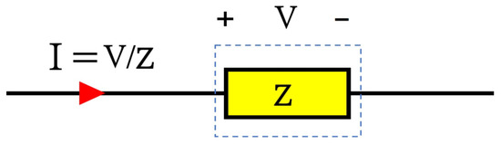
Figure 2. Ohmic current sensing principle.
In resistive methods (such as coaxial shunt), an ultra-high BW can be achieved (even up to a GHz [19,20]) by lowering parasitic inductance techniques. Their other advantages include simple passive circuitry (except the signal-conditioning part), small size, and cheap cost. Still, a significant problem of these schemes is connection (or placing the sensing element in series with the current trace), which also lacks electrical isolation, introducing parasitic elements (such as series inductance) to the power traces, and creates power loss and heat (that can also limit the current-sensing capacity of the element) [19,20,21]. One another big issue of ohmic current sensors is sensitivity change due to temperature variations [9], which is related to the temperature dependency of impedance values. Particularly, metal resistance can vary with any change in its temperature. In addition, as an ohmic current-sensing method, one technique of reading the inductor current is to read the inductor voltage and integrate it. This type of current sensing can also be affected by temperature variations in the inductor core.
3. DC Magnetometers
Magnetic sensors have evolved from ancient navigation devices to meet requirements for increased sensitivity, smaller sizes, and compatibility with electronics, for a wide range of applications, including current measurement [22]. The intensity of the magnetic field or flux density (B) (as the target of these sensors to detect) can be directly converted to the intensity of the electric current (I), based on Ampere’s law (1), in the context of current sensing:
I = 2πrB/μ,
In which r is the distance from the current-carrying conductor, and μ is the magnetic permeability. Furthermore, these sensors can now be easily integrated with other semiconductors, which is possible due to advances in miniaturization and manufacturing processes, where they have allowed for smaller and more efficient components that enable the sensors to be more accurate, reliable, and responsive [23]. However, there are some drawbacks to magnetic sensors, for example, they can be affected by outside magnetic fields, and they also require a power source [24]. Three widely used magnetic sensors for current sensing in power applications are as follows: (1) Hall-effect (HE) sensors; (2) magnetoresistive (MR) sensors; and (3) fluxgate sensors (FG).
3.1. Hall-Effect Sensors
HE sensors are based on the Hall-effect phenomenon that occurs across holes or voids in semiconductors or metals when a current is injected through contact near the edge or boundary of the gap [25]. Consequently, a voltage is produced on either side of a line connecting the current contacts when a perpendicular magnetic field is applied outside the gap within the metal or semiconductor material. Hence, HE detectors determine magnetic-field intensity according to the current sensed through the input interface, which must be subjected to signal conditioning to produce a significant output. Hall voltages are low-level signals (that can reach a maximum of a few dozen microvolts when surrounded by one gauss magnetic field), so an amplifier with low noise, high impedance, and moderate gain is required [26]. If the signal conditioner is not optimized for the application, it may not provide the highest level of accuracy. Due to interference from external fields, magnetic cores with high permeability can reduce interference effects by maximizing and concentrating magnetic fluxes from the measured current. As shown in Figure 3, the HE schemes can be implemented in either an open-loop or a closed-loop system, and depending on the needs of the application, they can be either with a magnetic core or they can be coreless. Closed-loop systems can help reduce nonlinearities by providing feedback to the system and adjusting the parameters accordingly, which allows the system to compensate for thermal drift. Furthermore, it is important to note that HE schemes typically have response speeds way lower than 100 kHz, and adding a CT configuration to the system can improve the sensing BW in the closed-loop system [9].
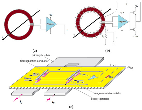
Figure 3. Different Hall-effect sensors’ topology: open loop with a core (a), closed loop with a core (b), and closed loop core-less (or compensated MR) (c) [9].
3.2. Magnetoresistive Sensors
The concept for MR sensors was first reported by Hunt in 1971, though magnetoresistance was discovered by Lord Kelvin in 1857 [27]. MR sensors can detect changes in both the strength and direction of the magnetic field by adjusting their resistance, which makes them suitable for a variety of applications, such as current sensing. Because of the special material used in making these sensors (usually a mixture of iron and nickel alloys), in addition to being exceptionally small and robust, they consume very little energy [28]. The anisotropic magnetoresistive (AMR) and giant magnetoresistive (GMR) sensors have attracted more attention among the various types of MR, owing to their ease of use and physical characteristics [22]. Other types of MR sensors, such as tunneling magnetoresistance (TMR) sensors, are usually more accurate and precise than AMR and GMR sensors [28], and due to their small size and outstanding performance, TMR sensors are now becoming more popular for power electronics applications. To enhance the linearity of the MR sensor and compensate for any thermal differences, MR sensors are usually installed within a Wheatstone bridge, which enhances the linearity of the sensor [29]. Figure 4 depicts the physical structure of three different MR sensors.
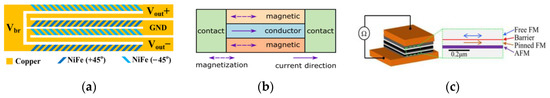
Figure 4. Physical structures of MR sensors: AMR (a), GMR (b), TMR (c) [28].
3.3. Fluxgate Sensors
FG technology sensors take advantage of magnetic core saturation, whereby passing a current close to the sensing core and measuring the flux, the core can be saturated and then unsaturated to measure the relative current that causes the magnetic field [9,28]. Parallel FG sensors are characterized by parallel excitation fields, whereas orthogonal FG sensors have excitation fields perpendicular to the sensitivity axis [28]. In Figure 5, an example of a parallel FG sensor can be seen. A sense coil is coupled with a signal-conditioning circuit, as well as a compensation coil, so that closed-loop control can be implemented within the circuit, in which the sensor output is integrated to achieve high loop gain. From a technical perspective, the integrator is connected to the differential driver that runs an opposing compensation current out of the inner compensation coil. By generating an inverse magnetic field in the compensation coil, the sense coil’s initial field returns to zero, where the compensation coil constantly generating a magnetic field and nonlinearities in the field caused by the input signals are compensated for. With outstanding accuracy, FG elements are continuously propelled in and out of saturation, maintaining zero-hysteresis control, and the shunt resistor senses the current produced by the external current in proportion to that produced by the external field, ensuring steady gain and high linearity. An FG sensor is typically considered to be the most accurate magnetometer among all the different magnetic-field detectors available today [9,28]. However, FG sensors have certain limitations, such as complex control circuitry, which was traditionally a major problem when considering their size and makes the scheme relatively expensive in comparison with other types [9], but as a result of the coming-of-age of solid-state technology, IC-level FG sensors can solve the problem of size and cost [13].
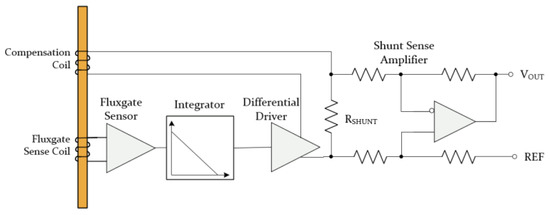
Figure 5. The block diagram and circuitry of a parallel fluxgate scheme.
Several advantages are associated with magnetic-field detectors being utilized as current sensors, including DC measurement capability, ease of application, low cost, and good isolation, while the disadvantages of these sensors typically include their low BW, interference with external magnetic fields, their susceptibility to EMI noises (especially when used in conjunction with metal plates that sense), and their limited sensing range, which must always be compromised when integrated into power electronics.
4. Inductive Current Sensors
Coils, whether they have a magnetic core, can always be subjected to a passive or electronic conditioning circuit to measure the alternative current (AC) using Faraday’s law of induction (2) [11,12]:
in which M is the mutual inductance between the coil and the conductor. From (2), induced voltages in higher-frequency ranges are larger than those in lower-frequency ranges, which means that this type of scheme is more accurate at higher frequencies (although only up to the coil’s resonant frequency, parasitic values will dampen the induced voltages at frequencies higher than the resonant frequency [30]), and there is no induced voltage when the coil is in a DC or a static magnetic field (di/dt = 0). By increasing the number of turns in the coil, the induction voltages are also increased, which will again affect the final BW to be decreased [12]. This is because the greater number of turns in the coil will also boost the overall inductance of the coil. In power applications, current transformers (CTs) (with a magnetic core and all passive circuits) and Rogowski coils (RCs) (employing electronics to compensate for the low gain of a core-less coil) are two common sensing schemes of this type [9,11,12,30].
Induced Voltage = −M di/dt,
4.1. Current Transformer
The CT is a type of coil-sensing realization that consists of three main parts, namely a coil or winding, a core, and a termination. The number of turns of the coil and the magnetic properties of the core can provide information regarding coil physics and some other electrical properties. CT sensing is versatile, as the number of turns and core properties can be adjusted to better suit various sensing requirements. The equivalent RLC of the coil can be calculated using coil and core physics, as shown in Figure 6, allowing for the determination of the upper and lower bands of working frequencies [11]. A resistor can be deployed at the termination of each CT for (RL) self-integration purposes, allowing it to be modified separately for a specific frequency range. For example, the resistor at the termination of the CT can be adjusted to shift the upper-frequency limit from 10 kHz to 100 kHz [31]. While CTs are ideal for many power applications due to their noise immunity, low cost, isolation, and passive circuitry, its integration has several drawbacks, including core saturation (limiting the sensing capacity and accuracy), fluctuations in core permeability at variable temperatures, low permeability at high frequencies, and bulkiness associated with having a magnetic core. However, for instance, to reduce the size of CTs while increasing their sensing ability and accuracy, nanocrystalline cores [32] are used instead of traditional magnetic cores.
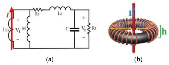
Figure 6. Equivalent circuit (a) and physical realization (b) of a toroidal current transformer [11].
4.2. Rogowski Coil
Although the RC working principle is very similar to CT, they usually use air-core coils instead of magnetic cores, so they generally require electronic integrator circuitry to compensate for the lower gain provided by an air core (especially at low frequencies) [30]. Since air-core coils do not experience magnetic saturation, they are often preferred in RC circuits because of their sensing capability, which is not as limited as it is with magnetic core coils, and they can also work at higher frequencies [31]. Air-core coils’ smaller dimensions and volume make them even more appealing for use in RC circuits because of their superior performance. In Figure 7, there are three major components of an RC current sensor: 1, coil; 2, termination; and 3, integrator [12,30,31]. Based on the RC’s frequency response, it can sense ultra-high frequencies, but like CT, it cannot detect DC/very low frequencies.
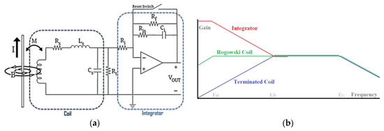
Figure 7. Equivalent circuit (a) and gain-frequency response (b) of a Rogowski Coil [30].
Technically, inductive-based current sensors are good AC transducers and are the only options to non-invasively measure high-frequency currents. In addition, they provide isolation due to their physical characteristics, and their greatest disadvantage may be their incapacity to detect DC. In Figure 7b, a typical value for Fa is usually Hz~kHz, while for Fb it is usually 100 kHz~MHz, and for Fc it is usually MHz~GHz.
5. Magneto-Optical Current Sensing
Magneto-optical (MO) current clamps, which utilize Faraday rotation when polarized light crosses an MO material in a magnetic field, have potential applications in power converters, where fiber-optic-packaging techniques can make MO current sensors relatively small, and high sensitivity can be achieved using rare-earth ion garnet materials [33]. In addition, MO current sensors are intrinsically immune to EMI noise and temperature variations. However, there are some potential challenges to implementing MO current sensors. One challenge is that MO materials currently available have limited bandwidth [9], which means that they may not be able to accurately measure HF currents. The cost-effectiveness of MO current sensors may be limited for some applications [9], which means it may not be feasible to employ them to measure very low currents. An MO current sensor application within a power electronics circuit is shown in Figure 8.
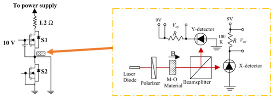
Figure 8. Schematic diagram of the optical sensing part placed in a leg test setup [33].
This entry is adapted from the peer-reviewed paper 10.3390/s23146481
This entry is offline, you can click here to edit this entry!