CO2 capture from coal- or natural gas-derived flue gas has been widely considered as the next opportunity for the large-scale deployment of gas separation membranes. Despite the tremendous progress made in the synthesis of polymeric membranes with high CO2/N2 separation performance, only a few membrane technologies were advanced to the bench-scale study or above from a highly idealized laboratory setting. Therefore, recent progress in polymeric membranes is reviewed in the perspectives of capture system energetics, process synthesis, membrane scale-up, modular fabrication, and field tests. These engineering considerations can provide a holistic approach to better guide membrane research and accelerate the commercialization of gas separation membranes for post-combustion carbon capture.
- polymeric membrane
- carbon capture
- scale up
- module
- process
1. Introduction
A promising approach to reduce the carbon emissions is post-combustion carbon capture. Under this concept, CO2 is captured at large stationary sources, such as power plants, with high purity (e.g., >95%) followed by the sequestration in geological formations (e.g., depleted oil fields and saline formations) or utilization (e.g., enhanced oil recovery and conversion into commodity chemicals)[1]. However, an inherent challenge in post-combustion carbon capture is the low CO2 concentration. Due to the use of air for combustion, flue gases are typically discharged at atmospheric pressure with 11–15% CO2 for coal-fired power plants and 4–8% for natural gas-fired power plants[2]. The limited thermodynamic driving force for CO2 separation imposes a great challenge to develop cost-effective capture technologies.
In order to close the gap between the membrane material synthesis in a lab-scale setting and the large-scale deployment in the field, however, a scalable fabrication of the membrane must be demonstrated, and the effective membrane process should be designed in accordance with the membrane performance and separation specifications. In addition, the membrane material needs to allow for a multiyear operation in the presence of flue gas contaminants, such as SOx, NOx, Hg, and particulate matter. The mass and momentum transfer in the membrane module should also be studied to guide the modular operation. Eventually, the membrane module and membrane process must be tested with actual flue gas to gain information on pretreatment, process dynamics, reliability of non-membrane components (e.g., rotating equipment), etc.
2. Membrane Process
2.1. Minimum Energy for Separation
Membrane separation is a pressure-driven process, and the process economics depends on the investment in fixed equipment and the parasitic energy extracted from the power plant to provide the transmembrane driving force. The capital cost is directly correlated with the system footprint, and hence inversely related to the CO2 permeance of the membrane. The energy penalty, however, is mainly determined by the membrane selectivity and the process design. In order to understand the energy demand for post-combustion carbon capture and the importance of the membrane selectivity, the minimum work for separation is discussed in this section.
For an ideal reversible process, the minimum work for separation is the difference in the Gibbs free energy of the streams entering and leaving the process[3]. Several researchers have investigated the minimum work to separate CO2 from flue gas based on a simplified process as shown in Figure 1a[3][4][5]. The CO2 concentration fed to the process is determined by the source of flue gas, and the composition of the nitrogen vent stream relies on the CO2 capture rate. As shown in Figure 1b, the minimum work to compress and liquefy CO2, on a per ton CO2 basis, remains constant for the condition specified[4]. The minimum work for separation, however, increases with decreasing feed CO2 concentration or increasing capture rate. For a U.S. coal-fired power plant with an average CO2 concentration of 13% in the flue gas, capturing 90% of the CO2 requires a minimum work of 42.1 kWh/ton. A more demanding minimum work of 62.6 kWh/ton is needed for 90% carbon capture from the natural gas-derived flue gas with 4% CO2.
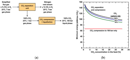
Figure 1. (a) Simplified process schematic of CO2 separation and compression/liquefaction for a simplified flue gas mixture of CO2 and N2; (b) Minimum energy per metric ton of CO2 captured as a function of CO2 concentration in a mixture of CO2 and N2. Reproduced with permission from[4]. Copyright American Chemical Society (ACS), 2012.
If the work for 90% CO2 separation is sourced from the electricity generated from the same coal-fired power plant, the minimum parasitic energy consumes 4.22% of the plant net generation[6]. It should be noted that no practical separation process can operate with the minimum work since it requires an infinitely large system footprint. In reality, separation processes typically render second-law efficiencies, defined as the ratio of minimum to actual energy consumption, in the range of 5–40%[7]. Therefore, the actual energy consumption for a membrane process is at least ca. 10% of the power plant output. It is difficult to analyze the second-law efficiency of a membrane process purely based on first principles. However, this efficiency is typically inversely related to the membrane selectivity, since a lower selectivity allows for more N2 permeation through the membrane, meaning that more lost work that cannot be used to extract any free energy. Combining the high minimum work for separation and the limited second-law efficiency, it is paramount to develop highly CO2-selective membranes and membrane processes for post-combustion carbon capture.
2.2. Process Synthesis
2.2.1. Single-Stage Process
The goal of process synthesis is to design a membrane architecture to meet the separation specifications. For given membrane properties, the operating conditions are optimized so that the capture cost and parasitic energy are minimized. The thermodynamics exercise in Section 2.1 suggests that there is a trade-off between the separation work and equipment cost. An optimization to reduce the parasitic energy tends to increase the second-law efficiency, while an optimization towards capture cost tends to decrease the second-law efficiency. This optimization problem is further complicated by the stringent separation specifications for post-combustion carbon capture, which require a >95% pure CO2 to be produced at a capture rate of 50–90%. As a pressure-driven process, the membrane is best suited for bulk separation, and a separation factor greater than 100 is rare for commercial membranes and processes[8].
The demanding separation requirement is best exemplified by various studies on the single-stage membrane process, where the flue gas is separated into a CO2-lean retentate and a CO2-rich permeate[9][10]. Gabrielli et al. studied the attainable CO2 recovery and purity for a single-stage membrane process with different permeate-to-feed pressure ratios and membrane selectivities[11]. As shown in Figure 2a, the CO2 purity increases with decreasing permeate-to-feed pressure ratio, indicating a high purity product stream can only be obtained with a large transmembrane driving force. However, even at a permeate-to-feed pressure ratio of 0.1, the product purity is less than 80% for a membrane with a CO2/N2 selectivity of 50. Further reducing the pressure ratio could improve the enrichment factor but at the expense of process economics. Therefore, a 95% CO2 purity can only be achieved by increasing the membrane selectivity or reducing the CO2 recovery.
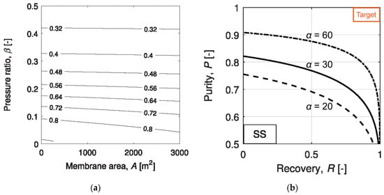
Figure 2. (a) CO2 purity map at different membrane areas and permeate-to-feed pressure ratios of a single-stage membrane process with a CO2/N2 selectivity of 50; (b) Attainable CO2 recovery and purity for a single-stage membrane process with CO2/N2 selectivities of 20–60. Reproduced with permission from[11]. Copyright Elsevier, 2017.
The trade-off between the CO2 recovery and purity was also studied by Gabrielli et al. for a single-stage membrane process[11]. As seen in Figure 2b, the purity-recovery Pareto fronts were generated for CO2/N2 selectivities in the range of 20–60 and permeate-to-feed pressure ratios between 0.01 and 1. Even at a low CO2 recovery of 50%, a CO2 purity greater than 95% is unattainable with a CO2/N2 selectivity of 60. Such a demanding selectivity is beyond the capability of most polymeric membrane materials as surveyed, except for a few reactive polymers relying on facilitated transport. Similar studies were also conducted by Zhai and Rubin[12] and Khalilpour et al.[13] with CO2/N2 selectivities up to 200. Their results suggest that a CO2/N2 selectivity > 200 and a permeate-to-feed pressure ratio < 0.05 are required for the 95% CO2 purity; however, the CO2 recovery must be restricted below 50%. In all, a single-stage process might be used for partial carbon capture provided with the availability of a highly CO2-selective membrane. The economics of such a process, however, has not been seen in the literature.
2.2.2. Multi-Stage Processes
Limited by the practical transmembrane pressure ratio and the membrane selectivity, a single-stage membrane process cannot achieve a high degree of CO2 removal while remaining a purity of >95%. In order to tackle the stringent separation goal and balance the system footprint and energy consumption, various two-stage processes have been designed. Based on the configurations, two general structures can be distinguished: (1) enriching cascade with the permeate of the first stage fed to the second stage and (2) stripping cascade with the retentate of the first stage fed to the second stage. Infinite two-stage processes can be devised based on these two basic cascades by rearranging the rotating equipment. Figure 3 summarizes some of the common designs (E1–E5 as enriching cascades[12][14][15][16][17]; S1–S5 as stripping cascades[18][19][20]).
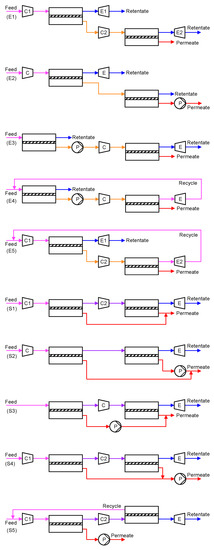
Figure 3. Two-stage membrane processes: (E1–E5) enriching cascades; (S1–S5) stripping cascades. Keys: = compressor; = expander; = vacuum pump. Stream: warmer color (e.g., red) = higher CO2 concentration; colder color (e.g., blue) = lower CO2 concentration.
In order to achieve a 90% CO2 recovery, an enriching cascade requires the first membrane stage to remove ≥90% of the CO2 in the flue gas. Recalling the purity-recovery trade-off as shown in Figure 2b, the first enrichment can, at best, render ca. 50–60% CO2 in the permeate, which is further enriched by the second membrane stage to achieve >95% CO2 purity. The high CO2 concentration fed to the second membrane stage provides a higher transmembrane driving force but also leads to a higher stage cut. Therefore, the enriching cascade configuration is typically more energy efficient but with a larger total membrane area[21][22]. On the contrary, the two membrane stages in a stripping cascade configuration each remove a portion of the CO2 from the flue gas and produce a permeate stream of >95% purity. However, the low CO2 concentration fed to the second stripping stage typically requires a large feed-to-permeate pressure ratio in order to achieve the purity. This results in an overall smaller membrane area but a high parasitic energy consumption[21].
In both configurations, pulling a vacuum on the permeate side is generally preferable to feed compression. This is because of the smaller flow rate of the permeate (CO2-rich) compared to that of the flue gas (N2-rich), albeit the lower efficiency and the larger footprint of a vacuum pump than those of a compressor[10]. In addition, current industrial vacuum pumps can only provide a practical vacuum down to 0.2 atm[23], in which case a mild feed compression should also be considered to further enhance the transmembrane driving force. The choice of the rotating equipment eventually depends on the trade-off between the capital and operational expenditures of the membrane process.
Of special interest are Processes E4 and E5 in Figure 3, where the retentate of the second enriching stage is recycled back to the feed of the first enriching stage. Because of the closed-loop recycling, the second enriching stage only needs to remove the CO2 from 50–60% down to ca. 13% (i.e., the CO2 concentration in the flue gas), which reduces its stage cut and membrane area. Zhao et al. studied Process E4 for a commercial membrane with a CO2 permeance of 185 GPU and a CO2/N2 selectivity of 43[21]. The feed pressure of the second enriching stage was set to 4 bar while the permeate vacuum of the first stage was varied to remove 50–90% of the CO2 from a flue gas containing 13.5% CO2. As shown in Figure 4, the two-stage enriching cascade can achieve 90% CO2 recovery with 95% CO2 purity. This study also compared the membrane process with the monoethanolamine (MEA) absorption. Even at 90% CO2 recovery, the membrane process exhibits a lower parasitic energy than that of the baseline MEA absorption. Specifically, the vacuum pump and the compression of the 95% CO2 account for the major energy consumptions, while the energy penalty caused by the feed compression is relatively small.
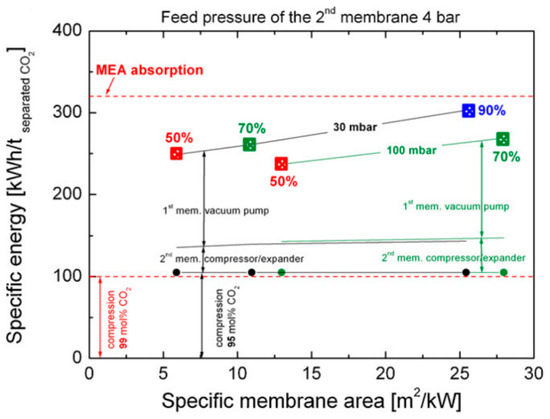
Figure 4. Comparison of parasitic energy consumptions of Process E4 in Figure 4 vs. monoethanolamine (MEA) absorption for CO2 removal rates of 50%, 70%, and 90%. A CO2 permeance of 185 GPU and a CO2/N2 selectivity of 43 were used for the membrane. Reproduced with permission from[21]. Copyright Elsevier, 2010.
The effect of membrane performance on Process E4 has also been widely investigated. Roussanaly et al. optimized the process performance for CO2 permeances ranging from 0–3500 GPU and CO2/N2 selectivities ranging from 0–200[24]. As shown in Figure 5, the relative cost efficiencies of the membrane process compared to the MEA absorption are graphically represented for different combinations of membrane permeance and selectivity. The green region represents the range of membrane properties that is definitively cheaper than the MEA-based capture with a margin greater than 25%. Clearly, a selectivity higher than 60 in combination with a CO2 permeance higher than 1000 GPU is required for the membrane to be competitive. The black line in Figure 5 corresponds to the optimal selectivity for a given permeance. For advanced membranes with a permeance greater than 1500 GPU (ca. 4 m3 (STP) m−2 h−1 bar−1 in Figure 5), a selectivity higher than 120 is required. Once again, this threshold is beyond the capability of most polymeric materials except the facilitated transport membranes.
In addition, a selectivity higher than 180 is not beneficial for the process economics. In this case, an increase in selectivity leads to a more CO2-rich permeate, which requires a larger feed compression or permeate vacuum to maintain the CO2 flux[9]. In all, this study suggests that a more permeable membrane needs to be accompanied by a higher CO2/N2 selectivity in order to fully capitalize on the benefit of the improved permeance.

Figure 5. Membrane properties required for Process E4 in Figure 3 to be cost-competitive vs. MEA absorption. Reproduced with permission from[24]. Copyright Elsevier, 2016.
The high selectivity requirement can be somewhat relaxed by using two different types of membranes in the two enriching stages. Xu et al. studied Process E5 in Figure 3 and proposed the use of a highly permeable but less selective membrane in the first enriching stage, and the use of a highly selective but less permeable membrane for the second enriching stage as shown in Figure 6a[25]. As discussed previously, the CO2 removal for the first stage needs to be as high as 90%, and the CO2 purity in the permeate is less than 50% regardless of the membrane selectivity. Therefore, a highly permeable membrane can be used in this stage for the bulk separation. In the second stage, a more selective membrane must be used in order to further purify the CO2 to >95%.
Not surprisingly, the capture cost reduces with increasing CO2 permeances of both stages (Figure 6b). However, the optimal selectivity for the first stage is at 40 with a feed pressure of 6–7 atm (Figure 6c). Contrarily, the selectivity of the second stages should be increased to 105 and the optimal feed pressure also needs to be increased to ca. 8 atm (Figure 6d). Based on this assessment, they proposed the use of the Generation 2 Polaris™ membrane (Membrane B in Figure 6a: 2000 GPU, 50 selectivity[26]) developed by Membrane Technology and Research (MTR) for the first stage and an amine-containing facilitated transport membrane (Membrane A in Figure 6a: 700 GPU, 140 selectivity[27]) developed by The Ohio State University (OSU) for the second stage.
This study indicates that the membrane performance for each stage in a multi-step process should be optimized individually due to the different feed compositions and stage cuts. In addition, only the feed compression was considered in this study, which concluded with relatively high feed pressures of 6–8 atm. A permeate vacuum should be considered at least for the second stage in order to further explore possibilities for a better process economics.
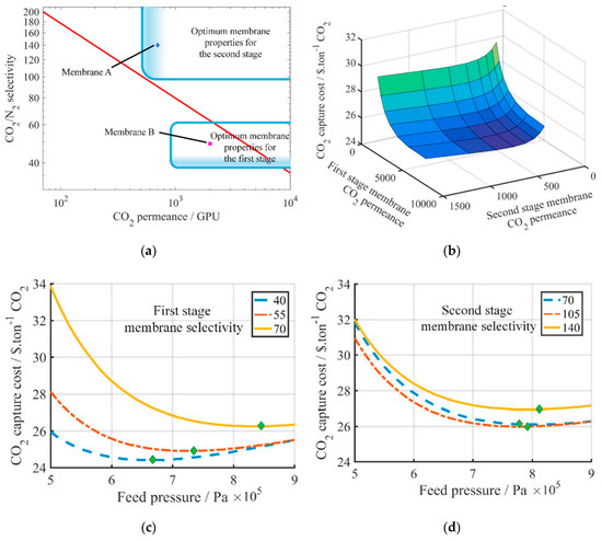
Figure 6. (a) Proposed scheme using two different types of membranes in Process E5 of Figure 3; (b) Effect of CO2 permeances of the two membrane stages on the capture cost (green = higher cost; blue = lower cost); (c) Effect of the first stage selectivity on the capture cost (second stage: 6 bar feed pressure, 140 selectivity); (d) Effect of the second stage selectivity on the capture cost (first stage: 6 bar feed pressure, 49 selectivity). Reproduced with permission from[25]. Copyright Elsevier, 2019.
Another variation of the Enriching Cascade E5 is to recycle a portion of the CO2-lean retentate as an internal sweep gas[22][28]. This option is of particular interest for highly CO2-selective membranes since the sweep gas can provide an additional transmembrane driving force to fully utilize the highly selective feature. Han and Ho proposed a two-stage retentate recycle process as shown in Figure 7a, where 15% of the retentate (ca. 92% N2) of the first enriching stage is recycled back to the permeate side as a countercurrent sweep[28]. The retentate recycle enhances the CO2 permeation through the first enriching stage; therefore, the feed pressure can be reduced to ca. 3.5 atm compared to the 6–8 atm in the work by Xu et al. (see Figure 7c,d). More importantly, the N2-rich retentate recycle reduces the N2 permeation through the first enriching stage. This feature minimizes the N2 loss from the feed to the permeate side through the membrane, thereby more compression work is recovered by the retentate expander of stage one.
Han and Ho and their coworkers also applied this design concept to an amine-containing facilitated transport membrane, in which the CO2 permeance increases with reducing CO2 partial pressure due to the mitigated carrier saturation phenomenon[29][30][31]. As shown in Figure 7b, the CO2 partial pressure reduces significantly upon the CO2 removal in the first membrane stage, especially at 90% CO2 recovery[28]. The reducing CO2 partial pressure leads to an uprising CO2 permeance along the feed flow direction. On the other hand, the N2 permeation is barely affected by the CO2 partial pressure since it depends on the solution-diffusion mechanism. Therefore, the separation becomes more efficient and selective owing to the mitigated carrier saturation. For the specific facilitated transport membrane studied, the membrane area can be reduced by ca. 12% if the carrier saturation phenomenon is considered.
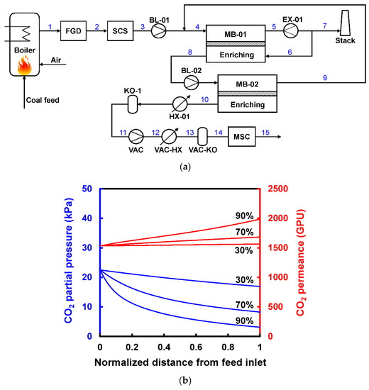
Figure 7. (a) Flow diagram of two-stage retentate recycle process to capture CO2 from coal-fired power plant; (b) Changes of CO2 partial pressure and the corresponding CO2 permeances in a facilitated-transport membrane module with 30%, 70%, and 90% CO2 recoveries. Reproduced with permission from[28]. Copyright ACS, 2020.
As discussed in Figure 3, the stripping cascade design is generally less cost-effective than the enriching cascades. By nature, it is challenging for the second stripping stage to produce high purity CO2 with a feed containing less CO2 than the flue gas. This issue can be partially addressed by Process S5 in Figure 3 via the permeate recycle. However, this option increases the feed flow rate to the first stripping stage, which inevitably requires a higher feed-to-permeate pressure ratio and thus a higher energy consumption. Merkel et al. from MTR integrated Process S5 with the boiler in a coal-fired power plant as shown in Figure 8a, in which the combustion air was used as the sweep gas for the second stripping stage[32]. The CO2-laden air was then fed to the boiler, which resulted in a higher CO2 concentration in the flue gas after combustion. The elevated CO2 concentration also provided a larger transmembrane driving force for the first stripping stage. The permeate of the first membrane stage was then further purified by cryogenic distillation to produce liquid CO2 with purity >95%. The air sweep eliminated the need for aggressive flue gas compression; the process could be operated with a feed at ambient pressure in conjunction with a permeate vacuum down to 0.2 atm for the first stage.
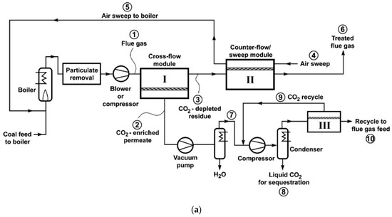
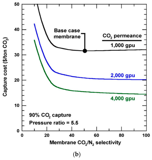
Figure 8. (a) Flow diagram of a two-step air sweep membrane process to capture and sequester CO2 from coal-fired power plant; (b) Effect of CO2/N2 selectivity on capture cost for 90% CO2 capture. Base case = 1000 GPU and 50 CO2/N2 selectivity. Reproduced with permission from[32]. Copyright Elsevier, 2010.
The cost sensitivity of the air sweep process was also conducted for MTR’s Generation 1 Polaris™ membrane (i.e., the base case membrane in Figure 8b) and hypothetical improved membranes with better permeances or selectivities[32]. As shown in Figure 8b, the CO2/N2 selectivity is deemed less important when it is above 50. Instead, the CO2 permeance is highlighted as the limiting factor for the capture cost, which stresses the need for highly permeable membranes with moderate CO2/N2 selectivity. The relaxed requirement for the selectivity is partially because of the use of cryogenic distillation. However, this energy-intensive operation adds onto the energy consumption and system complexity.
Ramasubramanian et al. adapted this design concept but focused on highly CO2-selective membranes[33]. In order to eliminate the need of the cryogenic distillation and make the system cost-effective, a CO2/N2 selectivity greater than 140 is required, which is within the reach of a number of facilitated transport membranes. It should be noted that the selectivity of the air sweep membrane stage is less important than that of the first vacuum stage. In the various studies for this air sweep process, the process optimization with respect to membrane performance and operating pressures generally points to a 50% CO2 removal by the vacuum stage, resulting in a retentate containing 8–9% CO2 and 70–80% N2 [12][18][22][32][33][34]. Because the N2 concentration is close to that in air, the N2 flux is low regardless of the CO2/N2 selectivity. Therefore, the membrane for the air sweep stage can be less selective as long as it possesses sufficient CO2/O2 selectivity to minimize the O2 loss from the sweep air to the treated flue gas. Therefore, using two different types of membranes similar to those discussed in Figure 6 might be another opportunity to further improve the design of the air sweep process.
2.2.3. Processes for Natural Gas-Derived Flue Gas
The processes discussed in Sections 2.2.1 and 2.2.2 all focus on the CO2 capture from coal-derived flue gases. Another important carbon-heavy source is the flue gas produced by a natural gas combined cycle (NGCC) power plant, where the high-temperature exhaust from the combustion turbine is passed to a heat recovery steam generator (HRSG) for generating steam and producing additional power by a steam turbine. Because of the excess air used in the combustion, the CO2 concentration in the flue gas is only 3–4%. Therefore, the carbon capture from a NGCC plant is more challenging than that from a coal-fired power plant.
In order to increase the separation driving force, a process so-called exhaust gas recycle (EGR) has been devised to recirculate a portion of the cooled flue gas after the HRSG (containing ca. 15% O2) back to the combustion turbine. Accordingly, the amount of fresh air is reduced and thereby, the CO2 concentration in the flue gas is increased[35]. Researchers from MTR adapted their combustion air sweep concept (see Figure 8a) to the EGR design, in which the carbon capture is integrated with the NGCC operation[4][36]. Figure 8a shows one of their designs[36]. As seen, a portion of the HRSG exhaust is directly recycled as the non-selective EGR. The remaining of the HRSG exhaust is treated by the two-step stripping cascade that is conceptually identical to that in Figure 8a, where the combustion air is used as the sweep for the second stripping stage. The CO2-laden air is fed to the combustion turbine, resulting in an additional selective EGR that helps increase the CO2 concentration to 13–21% for the membrane separation.
Baker et al. studied different allocations of the non-selective and selective EGRs for a membrane with 2500 GPU CO2 permeance and 50 CO2/N2 selectivity[36]. As shown in Figure 9b, a greater extent of the selective EGR renders a lower energy consumption, while an appropriate degree of non-selective EGR can drastically reduce the membrane area. The optimal case appears to be the direct recycling of 20% of the HRSG exhaust with the remaining treated by the stripping cascade. They also studied the effect of membrane selectivity, concluding that a higher selectivity (e.g., a selectivity of 100) can significantly reduce the energy consumption, especially at 90% CO2 capture.
A similar conclusion was arrived by Turi et al.[37], where a similar selective EGR process was studied for a facilitated transport membrane with a high CO2/N2 selectivity of 500[38]. The better selectivity relaxes the feed compression requirement for the first stripping stage and leads to lower energy consumption. Also, using a more selective membrane eliminates the need of the auxiliary enriching membrane stage and the cryogenic distillation unit in Figure 9a, which makes the membrane-based process competitive to the MEA absorption for NGCC carbon capture. In contrast, van der Spek et al. concluded that the membrane-based process is not superior to the MEA absorption for a membrane selectivity of 50[39].
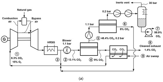
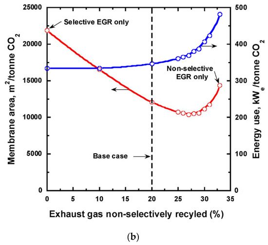
Figure 9. (a) Flow diagram of selective exhaust gas recycle (EGR) to capture and sequester CO2 from natural gas-fired power plant; (b) Effect of changing the non-selective EGR fraction on membrane area and energy use. Reproduced with permission from[36]. Copyright Elsevier, 2017.
Another membrane based selective EGR process was proposed by Lee et al. by using a sub-ambient membrane[40]. As shown in Figure 10, the non-selective EGR section is the same as that in MTR’s process (Figure 9a). However, the rest of the HRSG exhaust is cooled to −35 °C through a heavily heat-integrated cryogenic heat exchanger, which is then passed to a three-stage membrane process for CO2 capture and selective EGR. For certain polyimide membranes, it is known that the CO2/N2 selectivity increases without a huge reduction on the CO2 permeance when operated at a sub-ambient temperature[41][42]. Therefore, a CO2/N2 selectivity as high as 100 can be expected. The membrane separation section is a combination of the retentate recycle process as shown in Figure 7a and the air sweep process as shown in Figure 8a. The retentate-recycle part is responsible for the CO2 removal and enrichment to >83% purity; the air sweep stage strips the remaining CO2 and recycles it to the combustion turbine. Their cost analysis indicates that both the capture cost and energy consumption reduce significantly with increasing membrane selectivity. Although the cryogenic process enables the high membrane selectivity and provides a CO2 enrichment factor ca. 1.2, other highly selective membranes at elevated temperatures might also be good candidates for this process.
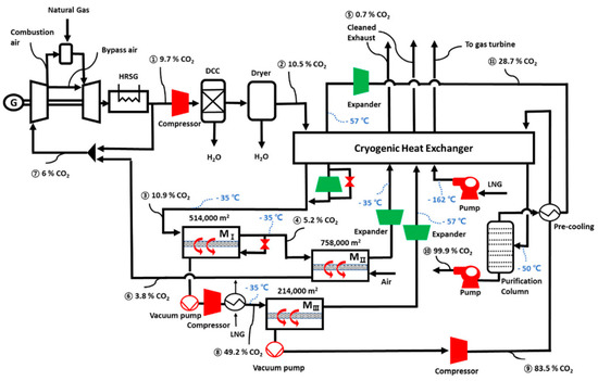
Figure 10. Flow diagram of the sub-ambient membrane process with selective and non-selective EGR for carbon capture from a natural gas combined cycle (NGCC) power plant. Reproduced with permission from[40]. Copyright Elsevier, 2020.
3. Membrane Scale-Up, Modular Fabrication, and Field Tests
An effort of the field test of SW modules was reported by OSU for their facilitated transport membranes containing both mobile and fixed-site amine carriers[27][29][43][44][45][46][47][48]. The roll-to-roll continuous membrane fabrication was demonstrated[44]. The 14”-wide prototype membrane was fabricated into a SW module with a membrane area of 1.4m2, which was tested at NCCC with actual flue gas containing 2 ppm SO2, 1.5–4 ppm NO2, and 7.6% O2 [29]. During the field trial, the SW module demonstrated a CO2 permeance of 1450 GPU and a CO2/N2 selectivity of 185 at 67 °C as shown in Figure 16h. A CO2 recovery of 44% was achieved by a single SW module with a CO2 purity of 94.5%. Overall, the module showed a 500-h stability despite various upsets due to flue gas flow rate variations and outages.
The stability and resilience of the facilitated transport membrane module have shed promising light on the following aspects. First, the amine carriers possessed essentially no volatility in the polymeric membrane, which eliminated the possibility of vaporization loss. Second, the low level of SO2 did not affect the transport performance of the carriers to a significant extent, which was likely due to the physical sorption of SO2 [49]; a cumulation of sulfur species in the membrane was not observed. Third, the chance of oxidation of the amine carriers at 67 °C was practically non-existent. Fourth, the polymer matrix was fully rubbery and not subject to a conformational relaxation, i.e., no physical aging. In addition, post-analysis of the tested membrane samples showed that no significant amounts of Cr, As and Se were deposited onto the membrane during the 500-h test at NCCC.
4. Conclusions
CO2 capture from coal- or natural gas-derived flue gas has been widely considered as the next opportunity for the large-scale deployment of gas separation membranes. Despite the advances in the synthesis of high-performance membrane materials, the modular fabrication of the membrane is rarely demonstrated in scale, and the membrane durability is seldomly tested with actual flue gas. In addition, the targeted CO2 recovery and purity of most membrane processes are yet to be verified in the field. The lack of experience in the field operation of a membrane system imposes the greatest challenge for its commercialization. Therefore, the recent progress in the engineering of polymeric membranes for post-combustion carbon capture has been reviewed in terms of capture system energetics, process synthesis, membrane scale-up, modular fabrication, and field tests. The key conclusions and remarks are as follows:
(1) The CO2 capture from a dilute source such as flue gas is intrinsically energy-intensive, showcasing low-energy consumption benefits of membrane process. The assignment of proper transmembrane driving force is the key to balance the second-law efficiency and the footprint of a membrane system.
(2) Limited by the membrane selectivity and practical feed-to-permeate pressure ratio, a single-stage membrane process can only partially capture the CO2. For a higher CO2 recovery, a multi-stage cascade design is mandatory.
(3) Enriching and stripping cascades are both suitable for 90% CO2 recovery, provided that sophisticated recycling streams are designed in the processes to enhance the CO2 flux. In order to achieve a >95% CO2 purity, a CO2/N2 selectivity greater than 50 is needed to make the process feasible. However, a higher selectivity (e.g., >100) is generally required for an optimized membrane-alone process.
(4) HF and SW modules are the preferred modular configurations due to their higher packing density and ease of manufacturing. Although less studied, PF modules also have applications in post-combustion carbon capture, especially in pre-pilot studies and situations where a high-pressure drop is unavoidable.
(5) The actual flue gases are invasive to the membrane operation. The frequently encountered challenges include the fouling by the particulate matter, the chemical degradation caused by SOx and NOx, heavy metal deposition, and water-induced plasticization. These factors should be considered during the membrane development. In addition, flue gas pretreatment should be emphasized prior to a field trial.
This entry is adapted from the peer-reviewed paper 10.3390/membranes10110365
References
- Barteau, M.A.; Dunn, J.; Allen, D.; Burkart, M.D.; Gaffney, A.M.; Gupta, R.; Hazari, N.; Kanan, M.; Kenis, P.; Klee, H. Gaseous carbon waste streams utilization: Status and research needs. AGUFM 2018, 2018, GC41A-03.
- Black, J. Cost and Performance Baseline for Fossil Energy Plants Volume 1: Bituminous Coal and Natural Gas to Electricity, 2nd ed.; Final report; National Energy Technology Laboratory: Irving, TX, USA, November 2010.
- McGlashan, N.; Marquis, A. Availability analysis of post-combustion carbon capture systems: Minimum work input. Proc. Inst. Mech. Eng. C J. Mech. Eng. Sci. 2007, 221, 1057–1065.
- Merkel, T.C.; Wei, X.; He, Z.; White, L.S.; Wijmans, J.; Baker, R.W. Selective exhaust gas recycle with membranes for CO2 capture from natural gas combined cycle power plants. Ind. Eng. Chem. Res. 2012, 52, 1150–1159.
- Herzog, H.; Meldon, J.; Hatton, A. Advanced post-combustion CO2 capture. Clean Air Task Force 2009, 1, 39.
- Abhoyjit S. Bhown; Brice C. Freeman; Analysis and Status of Post-Combustion Carbon Dioxide Capture Technologies. Environmental Science & Technology 2011, 45, 8624-8632, 10.1021/es104291d.
- Kurt Zenz House; Antonio C. Baclig; Manya Ranjan; Ernst A. Van Nierop; Jennifer Wilcox; Howard J. Herzog; Economic and energetic analysis of capturing CO2 from ambient air. Proceedings of the National Academy of Sciences 2011, 108, 20428-20433, 10.1073/pnas.1012253108.
- Ho, W.S.W.; Sirkar, K.K. Membrane Handbook, reprint ed.; Kluwer Academic Publishers: Boston, MA, USA, 2001.
- Huang, Y.; Merkel, T.C.; Baker, R.W. Pressure ratio and its impact on membrane gas separation processes. J. Membr. Sci. 2014, 463, 33–40.
- Favre, E. Carbon dioxide recovery from post-combustion processes: Can gas permeation membranes compete with absorption? J. Membr. Sci. 2007, 294, 50–59.
- Paolo Gabrielli; Matteo Gazzani; Marco Mazzotti; On the optimal design of membrane-based gas separation processes. Journal of Membrane Science 2017, 526, 118-130, 10.1016/j.memsci.2016.11.022.
- Haibo Zhai; Edward S. Rubin; Techno-Economic Assessment of Polymer Membrane Systems for Postcombustion Carbon Capture at Coal-Fired Power Plants. Environmental Science & Technology 2013, 47, 3006-3014, 10.1021/es3050604.
- Kaveh R. Khalilpour; Ali Abbas; Zhiping Lai; Ingo Pinnau; Modeling and parametric analysis of hollow fiber membrane system for carbon capture from multicomponent flue gas. AIChE Journal 2011, 58, 1550-1561, 10.1002/aic.12699.
- Yang, D.; Wang, Z.; Wang, J.; Wang, S. Potential of two-stage membrane system with recycle stream for CO2 capture from postcombustion gas. Energy Fuels 2009, 23, 4755–4762.
- Zhao, L.; Menzer, R.; Riensche, E.; Blum, L.; Stolten, D. Concepts and investment cost analyses of multi-stage membrane systems used in post-combustion processes. Energy Procedia 2009, 1, 269–278.
- Hussain, A.; Hägg, M.-B. A feasibility study of CO2 capture from flue gas by a facilitated transport membrane. J. Membr. Sci. 2010, 359, 140–148.
- Zhao, L.; Riensche, E.; Blum, L.; Stolten, D. How gas separation membrane competes with chemical absorption in post-combustion capture. Energy Procedia 2011, 4, 629–636.
- Franz, J.; Schiebahn, S.; Zhao, L.; Riensche, E.; Scherer, V.; Stolten, D. Investigating the influence of sweep gas on CO2/N2 membranes for post-combustion capture. Int. J. Greenh. Gas Con. 2013, 13, 180–190.
- He, X.; Fu, C.; Hägg, M.-B. Membrane system design and process feasibility analysis for CO2 capture from flue gas with a fixed-site-carrier membrane. Chem. Eng. J. 2015, 268, 1–9.
- Pfister, M.; Belaissaoui, B.; Favre, E. Membrane gas separation processes from wet postcombustion flue gases for carbon capture and use: A critical reassessment. Ind. Eng. Chem. Res. 2017, 56, 591–602.
- Zhao, L.; Riensche, E.; Blum, L.; Stolten, D. Multi-stage gas separation membrane processes used in post-combustion capture: Energetic and economic analyses. J. Membr. Sci. 2010, 359, 160–172.
- Bocciardo, D.; Ferrari, M.-C.; Brandani, S. Modelling and multi-stage design of membrane processes applied to carbon capture in coal-fired power plants. Energy Procedia 2013, 37, 932–940.
- Yang Han; W.S. Winston Ho; Recent advances in polymeric membranes for CO2 capture. Chinese Journal of Chemical Engineering 2018, 26, 2238-2254, 10.1016/j.cjche.2018.07.010.
- Simon Roussanaly; Rahul Anantharaman; Karl Lindqvist; Haibo Zhai; Edward Rubin; Membrane properties required for post-combustion CO2 capture at coal-fired power plants. Journal of Membrane Science 2016, 511, 250-264, 10.1016/j.memsci.2016.03.035.
- Jiayou Xu; Zhi Wang; Zhihua Qiao; Hongyu Wu; Songlin Dong; Song Zhao; Jixiao Wang; Post-combustion CO2 capture with membrane process: Practical membrane performance and appropriate pressure. Journal of Membrane Science 2019, 581, 195-213, 10.1016/j.memsci.2019.03.052.
- Lloyd S. White; Xiaotong Wei; Saurabh Pande; Tony Wu; Timothy C. Merkel; Extended flue gas trials with a membrane-based pilot plant at a one-ton-per-day carbon capture rate. Journal of Membrane Science 2015, 496, 48-57, 10.1016/j.memsci.2015.08.003.
- Varun Vakharia; Witopo Salim; Dongzhu Wu; Yang Han; Yuanxin Chen; Lin Zhao; W. S. Winston Ho; Scale-up of amine-containing thin-film composite membranes for CO2 capture from flue gas. Journal of Membrane Science 2018, 555, 379-387, 10.1016/j.memsci.2018.03.074.
- Yang Han; W.S. Winston Ho; Design of Amine-Containing CO2-Selective Membrane Process for Carbon Capture from Flue Gas. Industrial & Engineering Chemistry Research 2019, 59, 5340-5350, 10.1021/acs.iecr.9b04839.
- Han, Y.; Salim, W.; Chen, K.K.; Wu, D.; Ho, W.S.W. Field trial of spiral-wound facilitated transport membrane module for CO2 capture from flue gas. J. Membr. Sci. 2019, 575, 242–251.
- Han, Y.; Wu, D.; Ho, W.S.W. Simultaneous effects of temperature and vacuum and feed pressures on facilitated transport membrane for CO2/N2 separation. J. Membr. Sci. 2019, 573, 476–484.
- Han, Y.; Wu, D.; Ho, W.S.W. Nanotube-reinforced facilitated transport membrane for CO2/N2 separation with vacuum operation. J. Membr. Sci. 2018, 567, 261–271.
- Tim C. Merkel; Haiqing Lin; Xiaotong Wei; Richard Baker; Power plant post-combustion carbon dioxide capture: An opportunity for membranes. Journal of Membrane Science 2010, 359, 126-139, 10.1016/j.memsci.2009.10.041.
- Kartik Ramasubramanian; Hendrik Verweij; W.S. Winston Ho; Membrane processes for carbon capture from coal-fired power plant flue gas: A modeling and cost study. Journal of Membrane Science 2012, 21, 299-310, 10.1016/j.memsci.2012.07.029.
- Joseph A. Swisher; Abhoyjit S. Bhown; Analysis and optimal design of membrane-based CO2 capture processes for coal and natural gas-derived flue gas. Energy Procedia 2014, 63, 225-234, 10.1016/j.egypro.2014.11.024.
- Olav Bolland; Philippe Mathieu; Comparison of two CO2 removal options in combined cycle power plants. Energy Conversion and Management 1998, 39, 1653-1663, 10.1016/s0196-8904(98)00078-8.
- Richard W. Baker; Brice Freeman; Jay Kniep; Xiaotong Wei; Tim Merkel; CO2 capture from natural gas power plants using selective exhaust gas recycle membrane designs. International Journal of Greenhouse Gas Control 2017, 66, 35-47, 10.1016/j.ijggc.2017.08.016.
- D.M. Turi; Minh T Ho; Maria-Chiara Ferrari; Paolo Chiesa; Dianne Wiley; Matteo Romano; CO 2 capture from natural gas combined cycles by CO 2 selective membranes. International Journal of Greenhouse Gas Control 2017, 61, 168-183, 10.1016/j.ijggc.2017.03.022.
- Jin Huang; Jian Zou; W. S. Winston Ho; Carbon Dioxide Capture Using a CO2-Selective Facilitated Transport Membrane. Industrial & Engineering Chemistry Research 2008, 47, 1261-1267, 10.1021/ie070794r.
- Mijndert Van Der Spek; Davide Bonalumi; Giampaolo Manzolini; Andrea Ramirez; Andre´ P.C. Faaij; Techno-economic Comparison of Combined Cycle Gas Turbines with Advanced Membrane Configuration and Monoethanolamine Solvent at Part Load Conditions. Energy & Fuels 2017, 32, 625-645, 10.1021/acs.energyfuels.7b02074.
- Sunghoon Lee; Jin-Kuk Kim; Process-integrated design of a sub-ambient membrane process for CO2 removal from natural gas power plants. Applied Energy 2020, 260, 114255, 10.1016/j.apenergy.2019.114255.
- Chaubey, T. CO2 Capture by Cold Membrane Operation with Actual Power Plant Flue Gas (DE-FE0013163). In Proceedings of the 2016 NETL CO2 Capture Technology Meeting, Pittsburg, PA, USA, 8–12 August 2016.
- Hasse, D.; Ma, J.; Kulkarni, S.; Terrien, P.; Tranier, J.-P.; Sanders, E.; Chaubey, T.; Brumback, J. CO2 capture by cold membrane operation. Energy Procedia 2014, 63, 186–193.
- He, X.; Lindbråthen, A.; Kim, T.-J.; Hägg, M.-B. Pilot testing on fixed-site-carrier membranes for CO2 capture from flue gas. Int. J. Greenh. Gas Con. 2017, 64, 323–332.
- Hägg, M.-B.; Lindbråthen, A.; He, X.; Nodeland, S.; Cantero, T. Pilot demonstration-Reporting on CO2 capture from a cement plant using hollow fiber process. Energy Procedia 2017, 114, 6150–6165.
- Dai, Z.; Fabio, S.; Marino, N.G.; Riccardo, C.; Deng, L. Field test of a pre-pilot scale hollow fiber facilitated transport membrane for CO2 capture. Int. J. Greenh. Gas Con. 2019, 86, 191–200.
- Janakiram, S.; Santinelli, F.; Costi, R.; Lindbråthen, A.; Marino Nardelli, G.; Milkowski, K.; Ansaloni, L.; Deng, L. Field trial of hollow fiber modules of hybrid facilitated transport membranes for flue gas CO2 capture in cement industry. Chem. Eng. J. 2020, 127405.
- Sandru, M.; Kim, T.-J.; Capala, W.; Huijbers, M.; Hägg, M.-B. Pilot scale testing of polymeric membranes for CO2 capture from coal fired power plants. Energy Procedia 2013, 37, 6473–6480.
- Pohlmann, J.; Bram, M.; Wilkner, K.; Brinkmann, T. Pilot scale separation of CO2 from power plant flue gases by membrane technology. Int. J. Greenh. Gas Con. 2016, 53, 56–64.
- Colin A. Scholes; Abdul Qader; Geoff W. Stevens; Sandra E. Kentish; Membrane pilot plant trials of CO2 separation from flue gas. Greenhouse Gases: Science and Technology 2015, 5, 229-237, 10.1002/ghg.1498.