Your browser does not fully support modern features. Please upgrade for a smoother experience.
Please note this is an old version of this entry, which may differ significantly from the current revision.
Subjects:
Engineering, Manufacturing
In the realm of injection-molded parts, small length scale deformation defects such as sink marks often pose a major challenge to the aesthetics or functionality of the parts.
- sink mark
- volumetric shrinkage
- injection molding defect
1. Background
Injection molding of thermoplastic polymers is a widely used production process in which molten plastic is injected at high temperature into a metal cavity and cooled until it solidifies into a functional part. This process is essential to the mass production industry due to its scalability and low unit price, which keeps production costs manageable. Considering the low profit margins and high capital intensity associated with acquiring steel molds for plastic injection molding, it is critical to avoid costly mold and part design mistakes. Broken molds or visually deficient parts can have a devastating impact on profitability, which has led to the emergence of slogans such as “right on the first try”. To consistently achieve such production goals, simulation of the injection molding process is required. This involves solving the relevant partial differential equations for a given part geometry, considering appropriate boundary conditions as well as material models, and generating results that predict part moldability and quality. The prediction of warpage, i.e., the deviation of the shape of the produced part from the intended shape, is the pinnacle of modern simulation software [1,2,3].
In addition to warpage, there are many other defects that can occur in injection molded parts, and the goal of simulation is to predict as many defects as possible. One particular defect that occurs in injection molding is a “sink mark”, an undesirable depression on the surface of the part caused by localized high shrinkage of the material. Typically, sink marks occur in areas of the part that are thicker and cool more slowly, causing the surface to shrink away from the cavity wall more than adjacent areas. The local thickness is best defined as the diameter of a maximum sphere contained locally in the part, as shown in Figure 1 [4].
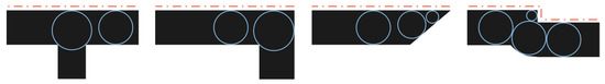
Figure 1. Various typical cross sections of plastic parts, with the differences in thickness illustrated by the different sizes of the maximum spheres. Surfaces where visual quality is vital and where deformation is of particular concern are marked by dashed lines.
2. Historical Overview of Injection Molding Process Modeling
An excellent historical overview of the academic field of injection molding simulation is provided by Peters Kennedy’s book [5], which serves as a common entry point for this field of study. The beginnings date back to 1960 when electronic computers were introduced and the first non-isothermal calculation of polymer flow in a simple rectangular plate cavity was performed [6]. This calculation involved modeling the increase in viscosity due to heat loss and discussing the resulting influence on the molding process. It then took 18 years of academic demonstrations before the first commercial company, Moldflow, was founded by Colin Austin in 1978. Engineers now had access to academic-grade code and the book Moldflow Design Principles [7], which still serves as the benchmark for the field. At that time, numerical techniques were used to reduce three-dimensional sheet-like geometries to equivalent flow in a plane [8].
With the increasing popularity of computer-aided design systems (CAD) in the 1980s, midplane shell models emerged. It became possible to solve the relevant equations using the finite difference method over the thickness of the part and to propagate them over the entire component using the finite element method [9]. It should be noted, however, that this type of modeling cannot capture the local variation in thickness. Academic work paved the way for modeling the packing phase, i.e., the time after the cavity is completely filled but the plastic is still molten and under pressure [10,11,12,13]. During this period, commercial companies began to develop the calculation of heat transfer both through the mold and through warpage. Moldflow led the way in warpage prediction, with a phenomenological approach, molding and simulating 28 sample plates with different parameters. The shrinkage of the sample plates was measured and used to calibrate the parameters of the “Residual Strain” model [14].
In the 1990s, CAD systems evolved to produce three-dimensional models. Full three-dimensional simulation using the “volume of fluid” method gained traction [15], but computer power remained limited and workarounds were developed. The most renowned approach is arguably dual domain technology [16], where the three-dimensional CAD geometry surface is meshed and computational cells are formed from matching mesh elements on the opposite surfaces of the part. As computing power increased, full three-dimensional simulation became viable [17], leading to a major expansion of simulation functionality. Increased accuracy enabled direct calculation of phenomena such as warpage [18] and three-dimensional velocity fields.
Open source software for injection molding simulation was virtually nonexistent until the early stages of development were begun in [19]. The resulting hydrodynamic flow simulation code [19] is based on a solver within the popular open source finite volume library OpenFOAM [20]. Over time, functionalities for the calculation of fiber orientation and crystallization were added [21]. Validation was performed [22] and good performance was shown.
3. Modeling the Deformation of Injection Molded Parts
During the injection molding process, the plastic is exposed to significant temperature and pressure changes as the phase boundary between solid and molten plastic progresses. Already-solidified layers prevent newly formed layers from freely changing shape, as they are all subject to elastomechanics as an integral domain. Early attempts to model shrinkage of injection molded parts relied only on thermodynamic (pvT) characterization of density [23] to predict both isotropic stress and shrinkage. Later, a line of research was devoted to viscoelastic formulations of the problem, which is complex from both theoretical and experimental point of view, as it is difficult to measure viscoelastic material properties in a satisfactory way [24]. Nevertheless, Douven [25] has shown that the stresses calculated by elastic and viscoelastic descriptions are similar. Moreover, it was shown in parallel by Baaijens [26] that the flow-induced stresses are two orders of magnitude smaller than the thermal and pressure-induced stresses. Therefore, the elastic thermomechanical approach proved sufficient, which provided the basis for its validity for a group of authors who worked on its increasingly rigorous formulation [27,28]. These efforts culminated in a paper by Jansen [29] in which a fully elastic thermomechanical method for calculating residual stress and shrinkage was developed. Their method showed that the boundary conditions at the interface between the plastic and the mold play a more decisive role than the increasingly complex material characterization. The objective of the present study is to take up Jansen’s approach and adapt it for a two-dimensional cross-section of an injection molded part. Specifically, the aim is to predict the deformation of the part surface with a characteristic length scale of the part thickness.
4. Modeling the Formation of Sink Marks
Sink marks were first discussed by Marchewka in 1974 [30]. In their study, plates with ribs were molded under different processing conditions and sink marks were visually assessed. The study focused primarily on the visibility of sink marks as a function of rib thickness, distance from the gate, and surface finish of the affected area. The results of the study led to the establishment of a design guideline that a rib thickness of less than 60%
of the base plate should not produce visible sink marks under most processing conditions. In addition, the study found that the distance from the gate is an important factor affecting the visibility of sink marks.
Later, Naka et al. [31] of what is now Phillips Corporation developed a method that used finite differences to calculate the evolving temperature distribution in a two-dimensional part cross section during injection molding. The temperature change was used as a thermal load for one-dimensional fiber elements that were independent of each other and constrained in the longitudinal direction. Only after the pressure in the cavity reached atmospheric values were the thermal, plastic, and elastic strains calculated over time and finally converted into displacements in the cross-sectional plane using the Poisson effect for the elastic strains. The numerical predictions of the method were compared with plates molded with an experimental tool where different values for rib thickness, rib height, and base plate thickness could be set. In addition, the mold was equipped with a pressure transducer to ensure that the pressure curve was known, although simulation of the packing phase was not yet generally available. The plates were molded with a profile measuring device and good agreement with the simulation was demonstrated.
In the late 1980s and early 1990s several influential doctoral studies were carried out in the Department of Mechanical Engineering at Ohio State University. The first thesis by Ramachandra [32] involved an extensive experimental investigation of sink mark depth on a test plate with varying rib thickness and rib root radius, as well as an investigation of the effects of process parameters such as melt temperature, mold temperature, and packing pressure. The results of the study have been cited in numerous subsequent studies, and have even found their way into the calibration report of a commercial software [33]. The second thesis by Reifschneider [34] formulated a finite element approach to calculate thermal shrinkage after the pressure in the cavity had dropped to zero and the plastic was able to separate from the mold walls. This work included a comprehensive discussion of the boundary conditions of the displacement field. Finally, Beiter [35] developed a geometric index to predict the depth of sink marks for a given packing pressure. These three theses represent important contributions to the understanding of sink mark formation in injection molding.
The research was continued by Mahesh Gupta of Michigan Technological University, who used the commercial software C-Mold [36] to simulate the injection molding process for the samples produced and measured by Ramachandra [32]. The researchers transferred the temperature results calculated by C-Mold to their own two-dimensional computational domain and continued calculating until a homogeneous temperature was reached. In this way, they ensured that all details from the filling phase and flow effects were taken into account. When the pressure of the C-Mold simulation dropped to zero, a structural analysis was carried out to calculate the thermal shrinkage. The material was assumed to be elastic-perfectly plastic, with temperature-dependent elastic modulus and yield stress around the glass transition temperature. The results were compared with measurements from Ramachandra [32] and Beiter [35]. In the next article by Shi and Ramachandra [37], the study was extended to analyze the necessary size of the computational domain to obtain the same results as in the full part analysis along with the influence of the mesh size. A year later, a three-dimensional analysis was introduced in the same way [38], and the plate used in Beiter’s study [35] was analyzed with two ribs crossing in the middle.
Subsequently, several experimental studies were conducted using methods such as design-of-experiment and genetic algorithms [39,40,41,42]. New modifications of conventional injection molding techniques have been explored, including rapid heating and cooling [43], gas-assisted injection molding [44], and microcellular injection molding [45]. An interesting departure from these studies is the use of artificial intelligence trained on a large dataset of process parameters and quality assessment results [46]. Finally, in the area of numerical sink mark prediction, one study [47] considered complex elastic material properties and a cooling rate-dependent equation of state for semi-crystalline plastic, but predicted only one-third of the measured sink mark depth.
All the studies mentioned above start by calculating the deformation of the solidifying plastic when the pressure at the point of interest reaches the atmospheric value and show that such an approach can correctly predict the depth of the sink marks. However, by disregarding the exact pressure history of the filling and packing phases, the large-scale warpage is conceptually decoupled from the small-scale deformations of the parts. Moreover, all of these studies employ fairly complex elastomechanical material models such as elastic-perfectly plastic [31,36,37,38], thermo-viscoplastic [34], or complex temperature- and strain rate-dependent [47] models. In this paper, we investigate the predictive power of a method (which we refer to as the “thermoelastic method”) that uses data available in material characterization reports of a commercial injection molding simulation software, treating the solid phase as an elastic material and the molten phase as either a pure liquid or a rubbery material with an elastic modulus reduced by three orders of magnitude.
This entry is adapted from the peer-reviewed paper 10.3390/polym15132841
This entry is offline, you can click here to edit this entry!