Your browser does not fully support modern features. Please upgrade for a smoother experience.
Please note this is an old version of this entry, which may differ significantly from the current revision.
Subjects:
Engineering, Biomedical
A design analysis of the power amplifiers developed for ultrasound applications was conducted because ultrasound applications require different types of power amplifiers, which are one of the most critical electronic components in ultrasound systems. To generate acoustic signals using transducers, which are among the most important mechanical devices in ultrasound systems, an appropriate output voltage, current, or power signal must be produced by a power amplifier.
- power amplifier
- ultrasound transducer
- ultrasound system
1. Introduction
Ultrasound has been widely used in various applications such as imaging, therapy, acoustic stimulation, cell sorting, and neuromodulation [1,2,3,4,5]. Ultrasound systems have been combined with several other modalities, such as magnetic resonance imaging (MRI), optical imaging, and positron emission tomography (PET) [6,7,8]. In addition, advanced integrated circuits have led to the development of wireless ultrasound systems by several companies, including General Electric, Siemens Healthineers, and Philips Medical [9,10,11]. Such an ultrasound system could provide physicians with prompt guidance in ambulances and emergency rooms [12,13].
An ultrasound system comprises a transmitter, a transducer, and a receiver [14]. The transmitter and receiver are electronic systems, whereas the transducer is a mechanical device [15]. The transmitter generates a high voltage or current depending on the type of transducer [16,17]. The receiver amplifies the weak echo signal received from the transducer and processes the data to construct images [18]. One of the last-stage electronic components of a transmitter is the power amplifier, which can affect the performance of the transducer [19,20]. Therefore, it is important to consider the performances of power amplifiers. Figure 1 shows the description of the power amplifier for transducer excitation. The input signal is amplified by the power amplifier, and the amplified signal is sent to trigger the transducer, which generates an acoustic wave delivered to the target. Afterward, the echo signal is generated from the transducer.
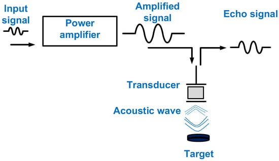
Figure 1. The power amplifier for transducer excitation.
Basic classifications can be provided for the areas of imaging and therapy in ultrasound research. Imaging is a common technique that uses a transmitter and receiver [21]. Therefore, the power amplifier in a transmitter can affect the performance of the system [22]. In a receiver, the echo signal data received by a transducer are converted into imaging data [23]. For imaging, it is preferable for power amplifiers to have a high gain and wide bandwidth [24]. The power amplifier bandwidth must be at least twice that of the transducer for harmonic imaging [24].
Both high- and low-power therapies are utilized [25]. High-power therapy utilizes high-intensity focused ultrasound (HIFU). The output power from the power amplifier is used to trigger the low-frequency transducer used for HIFU applications, and HIFU is commonly used in conjunction with an MRI machine to monitor sudden temperature variations [26]. For low-power (<1 W/cm2) therapy, power amplifiers have also been utilized to trigger the transducer; therefore, only acoustic power or combinational methods using acoustic waves with microbubbles have been used [27,28]. Neuromodulation research can be categorized as low-power therapy. Neuromodulation with acoustic stimulation has recently gained attention because of its ability to deliver drugs to the brain [29]. In neuromodulation research, the power amplifier is the last-stage electronic component before the transducer. The power amplifier needs to have high linearity because researchers do not know the amount of voltage or power that is needed to generate the proper outcome for the desired target [30]. In cell sorting, a transmitter has been used, and optical microscopy has been used to monitor the effect on cells [31]. A power amplifier is used to trigger the transducer to produce variable acoustic power [32,33]. The acoustic power generated is carefully controlled during cell sorting. In a previous study, the amount of output voltage generated from the power amplifier needed to be checked because there were some threshold voltages when producing a sorting effect on the cells [34].
Based on its output, a power amplifier can be classified as a voltage- or current-type amplifier, depending on the transducer device [35]. A voltage amplifier is used to generate a voltage output for a transducer that is fabricated using a piezoelectric material [36]. A current amplifier is used to generate a current output for a transducer that is fabricated using a capacitive material. This is known as a capacitive micromachined ultrasonic transducer (CMUT) [37,38]. Such a power amplifier is called a transimpedance amplifier because the input is a voltage, and the output is a current [39].
At the circuit design level, the power amplifiers used for ultrasound applications are classified into linear and nonlinear types based on the conduction angle of the transistor, which is the main component of the power amplifier [40]. Linear power amplifiers include Class-A, -B, and -AB power amplifiers, and nonlinear power amplifiers include Class-C, -D, -E, and -F power amplifiers. For linear power amplifiers, a large transformer-based power supply is required to supply precise direct current (DC) voltages [41]. For imaging applications, Class-A, -B, and -AB power amplifiers have been utilized. Compared with linear power amplifiers, nonlinear power amplifiers might use a switching-mode power supply to reduce the system size [42]. In nonlinear power amplifiers, the conduction angle of the transistor causes different voltage and current phase conditions [43]. Therefore, the power consumption should ideally be minimized. Different design criteria must be considered for each type of power amplifier. For example, in a power amplifier using a feedback resistor, the voltage gain can be reduced to extend the bandwidth, and a nonlinear power amplifier usually has high efficiency but high signal distortion [44].
2. Design Parameters of Power Amplifiers
A transistor is one of the fundamental components of a power amplifier. Therefore, proper transistor selection is the first step in designing a power amplifier [45]. For transistor selection, the circuit designer must examine the specifications of the transistor on the datasheet for discrete components or check the specifications of the transistor in the design kits for the integrated circuit [46,47,48]. The maximum gate–source voltage and drain–source voltage of the transistor must first be checked because the maximum DC bias voltages of the transistor are limited by these voltages [49]. The maximum drain current of the transistor must be considered because the amplified output current level must be lower than the maximum drain current of the transistor [50,51]. The parasitic gate–source, gate–drain, and drain–source capacitances must be considered [52]. The maximum operating frequency of the power amplifier can be limited by the transistor parasitic capacitances [52]. The maximum power consumption must be checked to avoid transistor failure [53]. After the careful selection of the transistor, the design parameters of the power amplifier are considered. The power amplifiers used for ultrasound applications utilize metal-oxide-semiconductor field-effect transistors (MOSFETs) lateral diffusion metal-oxide-semiconductors (LDMOSs), and double-diffused metal-oxide-semiconductors (DMOSs). LDMOSs and DMOSs are types of MOSFETs that operate under high-voltage or high-power conditions [54].
The design parameters must be discussed when selecting appropriate power amplifiers because the power amplifiers must work for transducers and systems. The design parameters of power amplifiers are typically the gain, bandwidth, harmonic distortion, linearity, and efficiency [55,56]. This section guides how to utilize each parameter and the parameters that need to be considered in the power amplifier design.
The gain of the power amplifier is the extent to which the amplitude of the input signal is amplified to generate the amplitude of the output signal [56]. The bandwidth is an important parameter because the maximum bandwidth of the power amplifier should be higher than that of the transducer.
Harmonic distortion is usually discussed in relation to the harmonic imaging method (HIM), which is a software algorithm used to obtain high-resolution images [57]. The harmonic distortion components of the echo signals generated by a transducer can be minimized in the signal-processing step. Some commercial power amplifiers provide harmonic distortion parameters in the datasheet so that researchers can estimate the extent to which the signal distortion of the power amplifier can affect the signal quality of the transducer.
Efficiency is an important parameter, particularly in wireless ultrasound systems [58,59,60]. It indicates how long the battery in the system can provide DC voltages. Efficiency can be regarded as an index showing how efficiently the energy can generate the output power to trigger the transducer. The drain efficiency or power-added power efficiency (PAE) parameters are also used in power amplifiers. The drain and power efficiency values are similar if the output power is much larger than the input power [61]. The power amplifier with high efficiency normally generates high signal distortions, so it could produce relatively high harmonic distortions from the transducers, which lowers the image resolution of the ultrasound system [62].
The linearity indicates the extent to which the input voltage of the power amplifier is increased [63,64]. The power amplifier contains input or output intermodulation points (IIP3 or OIP3). A higher IIP3 or OIP3 indicates that the input voltage, current, or power can be amplified to generate an output voltage, current, or power with little signal distortion up to that point (IIP3 or OIP3) [65,66]. Linearity is also related to the signal or harmonic distortion. For example, nonlinear power amplifiers usually have high efficiency but low linearity.
Figure 2 shows a symbol diagram of the design parameters to show the specific relationships because some design parameters have trade-off relationships. Basic information was obtained from the integrated circuit and power amplifier textbooks. For example, a higher gain for a power amplifier can lower the bandwidth [46]. Power amplifiers with a wide bandwidth may have low efficiency [67]. In Figure 2, the relationships between the parameters indicate that there are challenges in obtaining a high-performance power amplifier. Therefore, circuit design engineers must have the experience and intuition needed to obtain the proper performance from a power amplifier.
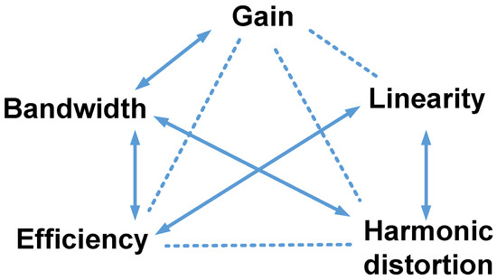
Figure 2. Design parameters of power amplifiers for ultrasound applications. The arrows represent inversely proportional relationships, and the dotted lines indicate other relationships.
This entry is adapted from the peer-reviewed paper 10.3390/mi14071342
This entry is offline, you can click here to edit this entry!