Your browser does not fully support modern features. Please upgrade for a smoother experience.
Please note this is an old version of this entry, which may differ significantly from the current revision.
EVs have the ability to run solely on electric propulsion or in conjunction with an internal combustion engine (ICE). The simplest sort of EV relies just on batteries as its source of energy; however, there are many variants that make use of a variety of other types of energy sources. These automobiles are hybrid electric models (HEVs). The Technical Committee 69 Electric Road Vehicles (ERV) of the International Electrical Technical Commission proposes that vehicles with two or more forms of energy source, storage, or converters can be classified as HEVs as long as at least one of them provides electrical energy.
- electric vehicles
- internal combustion engine
- BEV
- HEV
- PHEV
1. Battery Electric Vehicles (BEVs)
Given that a battery is the only source of energy for the powertrain of a BEV, as shown in Figure 1, the range that may be achieved by such a vehicle is directly proportional to the capacity of the battery [1]. A BEV is completely carbon dioxide (CO2) emission-free because it does not have a tailpipe or other source of exhaust emissions. BEVs have the potential to go between 100 and 250 km on a single charge while using 15 to 20 kWh for every 100 km driven. This range is determined by the characteristics of the vehicle. There is a range between 300 and 500 km for battery electric vehicle models that have larger battery packs [2]. However, battery electric vehicles (BEVs), in comparison to other types of EVs, have a substantial disadvantage due to their significantly reduced driving range and dramatically increased charging periods. The most effective way to address this issue would be to design and implement an EMS that is suitable for BEVs.

Figure 1. Structure of BEV circuit.
Compared to the three previous braking techniques, the one presented here increased the range to 20 km/kWh. This innovative braking technique could increase the range by 4.16 km/kWh compared to mechanical braking alone. One technique to expand the range of battery electric vehicles (BEVs) is to increase the battery pack’s capacity. However, it is possible that a battery pack with a large capacity is not useful because it requires a significant amount of space and significantly increases the weight of the vehicle [3]. This has a direct impact on the vehicle’s performance as well as its fuel economy, and it also raises the total cost of the vehicle. An electric three-wheel vehicle that is fully loaded (300 kg) and has a lithium-ion battery pack (LIB) that is 16 kWh has a range that is approximately 12.5% less than it would have with a half-load (150 kg) (from 200 to 175 km) [4].
Examining different driving styles is another method that can be used to extend the range of a battery electric vehicle (BEV) without having to increase the capacity of the battery. Controlling the flow of energy and power is one way that one might put this method into action when driving. An algorithm was proposed to cut down on journey time and the amount of gasoline used. The fact that this technique is based on a multi-objective algorithm enables it to produce results that are superior to those produced by other algorithms that have been examined. Some studies [5][6] have suggested a velocity profile optimization-based optimal control method to reduce energy consumption. The proposed algorithm was able to cut energy consumption by between 8 and 10%, thanks to its management of the driving duration and speed. These citations provide a workable answer to the problem of lowering the battery capacity while maintaining a lower overall energy consumption [7].
2. Hybrid Electric Vehicles (HEVs)
In accordance with the standards set forth by Technical Committee 69 (Electric Road Vehicles) of the International Electro-Technical Commission, a hybrid electric vehicle (HEV) is a motor vehicle that utilizes two or more energy sources, storage devices, or converters, at least one of which creates electricity. Unlike conventional vehicles, HEVs use several energy sources, storage, and/or converters [8]. Because BEVs have a limited driving range, hybrid electric vehicles (HEVs), which combine a traditional internal combustion engine (ICE) with a battery system, have become an appealing option. An electric motor is the only source of propulsion for a series hybrid electric vehicle, as shown in Figure 2a. In contrast, both an internal combustion engine (ICE) and an electric motor are connected to the gearbox of a parallel hybrid electric vehicle (HEV), which transmits power to the wheels simultaneously (see Figure 2b). Many studies have been conducted to determine the amount of fuel that parallel and series hybrid electric vehicles consume, as well as how efficiently they use their fuel. The study by [9], for instance, compared the amount of gasoline that was consumed by series and parallel HEV road sweeper trucks while keeping the same amount of power and traveling the same amount of distance.
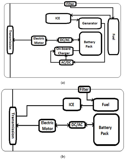
Figure 2. (a) Structure of series HEV circuit and (b) structure of parallel HEV circuit.
Based on the findings of the comparison, the series hybrid design (3.8 L/h) had a lower fuel consumption rate than the parallel hybrid design (6.2 L/h). When the vehicle was operating in the series hybrid mode, the internal combustion engine (ICE) kept its speed constant throughout the transport mode. Due to the fact that there are three different conversions that take (place mechanical, electric, and mechanical), parallel HEVs are theoretically considered to have smaller power conversion losses than series HEVs do. When the power splitting mode is engaged, it is possible to cut losses in the drive train, the engine, and the braking system [10][11]. This could lead to a gain in the fuel economy that ranges from 0.3 to 36.7%. In addition to this, the fuel efficiency of parallel HEVs can be up to 68 percent better than that of a traditional automobile. This substantial improvement in fuel efficiency was made possible, in part, by the implementation of regenerative braking, which refers to the recuperation of energy that would have otherwise been lost. As a consequence of these studies, series hybrid electric vehicles (HEVs) have been successfully deployed in transportation mode [12].
Mild hybrid electric vehicles, also known as MHEVs, are another form of hybrid electric vehicle (HEV) that are equipped with an electric motor and a battery that has a capacity that is on the lower end of the spectrum (10–20 kW) [13]. Although the hardware components of this form of EV and other types of HEVs are identical, the control algorithms used by each of these categories of vehicles are very different. Because the internal combustion engine is responsible for the majority of the production of the vehicle’s propulsion energy, a gasoline-powered hybrid electric vehicle (MHEV) is distinguished from other types of HEVs by having a lower hybridization power of approximately 15% and smaller driving electric components. This is due to the fact that the internal combustion engine is responsible for the majority of the production of the vehicle’s propulsion energy [14]. When it comes to energy management, the most difficult obstacle for HEVs to overcome is likely going to be the combination of many energy sources and optimization. In order to determine a pattern of a driving cycle’s energy consumption, a comprehensive modeling system, data from test runs, and simulator software that has been approved for commercial use are required. In addition, the data from the test runs are necessary in order to obtain the energy consumption [12].
3. Plug-In Electric Hybrid Vehicles (PHEVs)
The range of HEVs has increased, which has led to the development of PHEVs. Like HEVs, plug-in hybrid electric vehicles (PHEVs) have an internal combustion engine (ICE), an electric motor, a generator, and a battery. Regenerative braking can be replaced with utility grid charging. PHEVs are BEV/HEV hybrids [15]. Figure 3a,b shows different plug-in hybrid electric automobiles (PHEVs). Hybrid electric vehicles use “series” or “parallel” ICEs to charge the battery or provide traction.
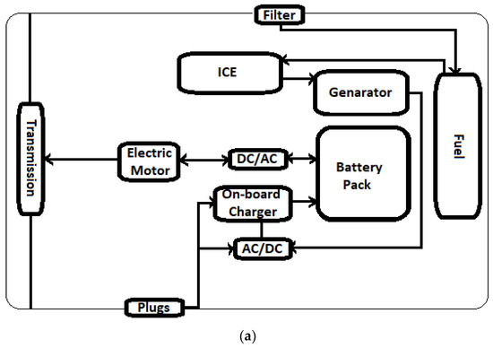
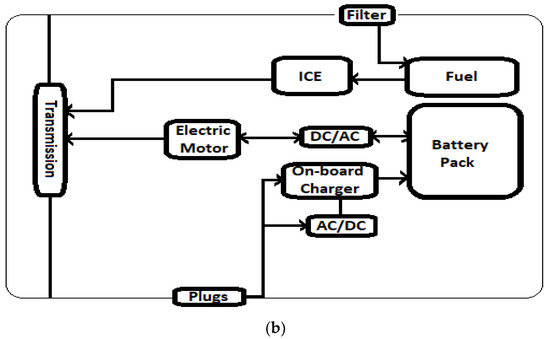
Figure 3. (a) Structure of series PHEV circuit and (b) structure of parallel PHEV circuit.
Larger battery packs are necessary for PHEVs because they can potentially charge off the grid, unlike HEVs. The maximum state-of-charge (SOC) that a hybrid electric vehicle (HEV)’s battery is allowed to hold is limited by the charge sustenance mode (CS). Depending on the driver’s preference, a plug-in hybrid electric vehicle (PHEV) can switch between the charge depletion (CD) mode (which prioritizes the electric motor over the internal combustion engine) and the pure electric (EB) mode [16]. The fuel consumption in parallel PHEVs was reduced using the charge depletion mode in this research. The urban dynamometer driving schedule (UDDS) reduced parallel PHEV fuel consumption by 7.1% over 64 km, 6.3% over 48 km, and 5.6% over 32 km. This study found that the PHEV’s CD control technique effectiveness increased proportionally with the test distance.
In the same way as with BEVs, when the battery capacity of PHEVs increases, the primary issue shifts to the charging time; as a result, charging strategies are required to maintain the vehicle’s performance. A fast charger can give a higher DC current capacity for car charging. Both standards support quick charging. In [17], they developed, implemented, and tested the V2G system. A vehicle with a fully functional CHAdeMO inter-face (VCI) at the physical and protocol levels was able to control communication and electrical transfer between the car and the charger. The VCI was fully implemented at both the physical and protocol standards. Plug-in hybrid electric vehicles and battery electric vehicles could shape the future of transportation by storing energy from the grid in their batteries and feeding it back into the transmission network when needed [18].
It was possible to achieve optimal charging timing for plug-in hybrid electric vehicles (PHEVs) by synchronizing a number of plug-in hybrid electric vehicles (PHEVs) inside a smart grid system. The findings reveal that it had an adequate level of robustness and provided values with a standard deviation that was less than 1 (=0.8425). Figure 4 illustrates the configuration of the powertrain used in series–parallel hybrid electric vehicles and plug-in hybrid electric vehicles [19]. HEVs and PHEVs that run in a series–parallel mode are able to make use of all of the benefits that are associated with running in either the series or the parallel mode. These benefits include increased fuel economy, increased range, and increased efficiency.
Figure 4. Hybrid EV series–parallel circuit layout: (a) series–parallel HEV; series–parallel plug-in hybrid electric vehicle (b).
A study on the efficiency of fuel usage in series–parallel plug-in hybrid electric vehicles was carried out by Zhao and Burke. Their research showed that a series–parallel PHEV using the UDDS (city driving) method had a fuel economy that was 18.1 km/L lower than a similar series shaft PHEV, which averaged 20.4 km/L. This information was derived by comparing the two types of PHEVs using the same driving strategy. As a result of the energy allocation and power management in the drive system, it provided a real-world example of the control method for series–parallel plug-in hybrid electric vehicle (PHEV) power management. This was possible since it was based on a drive system. The result brought the overall system’s efficiency up by 27.50 percentage points, from 19.3 to 24.6 km/L. Nonetheless, this type of vehicle is heavier, has a less sophisticated look, and carries a higher price tag [20].
Another type of plug-in hybrid electric car is an extended-range electric vehicle (EREV). In contrast to other types of PHEVs, the electric motor always powers the wheels, and the internal combustion engine doubles as a generator to keep the vehicle’s battery charged whenever it runs low or when the vehicle is in motion [21]. It is possible that the decreased consumption of mineral resources is due to the vehicle’s smaller size and the fact that there are fewer components overall. It is possible to achieve minimal fuel consumption since gasoline is only required to run the generator. The fact that the generator is the solitary component that is used in the process of providing electricity to the vehicle makes this outcome conceivable. The generator’s speed and torque can both be adjusted to achieve the highest possible levels of energy efficiency in order to cut down on the amount of money spent on fuel [22]. Because of the range extender, EREVs are able to travel further than BEVs; nevertheless, in order to compete with BEVs in terms of energy efficiency, they need to be much more compact.
This entry is adapted from the peer-reviewed paper 10.3390/su15129390
References
- Mansour, M.B.M.; Said, A.; Ahmed, N.E.; Sallam, S. Autonomous parallel car parking. In Proceedings of the 2020 Fourth World Conference on Smart Trends in Systems, Security and Sustainability (WorldS4), London, UK, 27–28 July 2020; pp. 392–397.
- Wang, Y.; Sun, W.; Lu, Y. Research on application in intelligent vehicle automatic control system. J. Phys. Conf. Ser. 2021, 1828, 012046.
- Jlili, A. Optimal Sizing and Sitting in Radial Standard System using PSO. Am. J. Sci. Res. 2012, 67, 50–58.
- Gholamian, S.A. Optimal Placement and Sizing of Capacitor and Distributed Generation with Harmonic and Resonance Considerations Using Discrete Particle Swarm Optimization. Int. J. Intell. Syst. Appl. 2013, 7, 42–49.
- Padma, M.; Sinarami, N.; Veera, V.C. Optimal Dg Placement for Maximum Loss Reduction in Radial Transmission System Using ABC Algorithm. Int. J. Rev.Comput. 2012, 3, 2076–3328.
- Taghikhani, M.A. DG Allocation and Sizing in Transmission Network using Modified Fuzzy Logic Algorithm. Int. J. Autom. Power Eng. 2019, 1, 10–19.
- Ataei, M.M. Real-Coded Genetic Algorithm Applied to Optimal Placement of Capacitor Banks for Unbalanced Transmission Systems with Meshed/Radial Configurations. Int. Energy J. 2014, 8, 51–62.
- Volkanovski, M.; Borut, M. Optimization of reactive power compensation in Transmission network. Elektrotehniški Vestn. 2009, 76, 57–62.
- Razavi, H.F. Voltage Profile Modification using Genetic Algorithm in Transmission Systems. In Proceedings of the World Congress on Engineering and Computer Science WCECS, San Francisco, CA, USA, 19–21 October 2016; pp. 24–26.
- Movahed, M. Evaluation of Power Loss Reduction with the place of Shunt Capacitors and Distributed Generation Power Plant in the Radial Transmission Systems using Genetic Algorithms. Am. J. Adv. Sci. Res. 2013, 1, 278–283.
- Russo, A. Distributed generation siting and sizing under uncertainty. In Proceedings of the IEEE Porto Power Tech Conference, Porto, Portugal, 10–13 September 2001; Volume 2, pp. 456–564.
- Hajizadeh, A.; Ehsan, M.M. PSO-Based Planning of Transmission Systems with Distributed Generations. Int. J. Electr. Electron. Eng. 2011, 2, 33–38.
- Karimi, M.; Shayeghi, H.; Banki, T.; Farhadi, P.; Ghadimi, N. Solving Optimal Capacitor Allocation Problem using DE Algorithm in Practical Transmission Networks. Przegląd Elektrotechniczny 2012, 88, 90–93.
- Shirdel, M. Applying BCO Algorithm to Solve the Optimal DG Placement and Sizing Problem. Electr. Electron. Eng. 2012, 2, 31–37.
- Perera, S. Voltage Support by Distributed Generation Units and Shunt Capacitors in Transmission Systems. IEEE 2016, 6, 3781–4241.
- Ziari, I. A New Method for Improving Reliability and Line Loss in Transmission Networks. In Proceedings of the AUPEC 2010, Christchurch, New Zealand, 5–8 December 2019.
- Sedighizadeh, M.; Rezazadeh, A. Distributed Generation Allocation to Improve Steady State Voltage Stability of Transmission Networks Using Particle. World Acad. Sci. Eng. Technol. 2018, 4, 213–245.
- Noh, B.; Park, H.; Yeo, H. Analyzing vehicle-pedestrian interactions: Combining data cube structure and predictive collision risk estimation mode. Accid. Anal. Prev. 2021, 152, 105970.
- Elma, O.; Adham, M.I.; Gabbar, H.A. Effects of Ultra-Fast Charging System for Battery Size of Public Electric Bus. In Proceedings of the IEEE 8th International Conference on Smart Energy Grid Engineering (SEGE), Oshawa, ON, Canada, 12–14 August 2020.
- Brenna, M.; Foiadelli, F.; Leone, C.; Longo, M. Electric Vehicles Charging Technology Review and Optimal Size Estimation. J. Electr. Eng. Technol. 2020, 15, 2539–2552.
- Das, H.S.; Rahman, M.M.; Li, S.; Tan, C.W. Electric vehicles standards, charging infrastructure, and impact on grid integration: A technological review. Renew. Sustain. Energy Rev. 2020, 120, 109618.
- Wang, M.; Zhong, J. A Novel Method for Distributed Generation and Capacitor Optimal Placement considering Voltage Profiles. In Proceedings of the IEEE Power Engineering Society Summer Meeting, Denver, CO, USA, 17–21 July 2022; Volume 3, p. 978–1-4577-1002-5/11/2011.
This entry is offline, you can click here to edit this entry!