Your browser does not fully support modern features. Please upgrade for a smoother experience.
Please note this is an old version of this entry, which may differ significantly from the current revision.
Subjects:
Engineering, Chemical
The electrocatalytic CO2 reduction reaction (CO2RR) to formic acid has gained significant attention as a potential environmentally friendly approach to reducing CO2 emissions and producing carbon-neutral liquid fuels. However, several challenges must be addressed to achieve the production of high-purity and high-concentration formic acid through CO2RR. One major challenge is the formation of a formate mixture instead of pure formic acid in conventional reactors. This requires costly downstream purification and concentration processes to obtain pure formic acid.
- carbon dioxide
- CO2 electroreduction
- formate
- formic acid
1. Introduction
Anthropogenic activities, particularly the excessive usage of fossil fuels, have led to a significant increase in the level of CO2 in the atmosphere since the beginning of the industrial period [1]. This rise in CO2 levels has contributed to a climate crisis, evident from the recent occurrence of extreme weather events such as floods and forest fires. To address these challenges and reduce greenhouse gas emissions, substantial efforts have been directed toward finding ways to convert CO2 into value-added chemicals or fuels, including methanol (CH3OH), formate (HCOO−)/formic acid (HCOOH), carbon monoxide (CO), syngas (CO and H2), and ethylene (C2H4) [2]. Among the numerous CO2 conversion approaches such as biochemical, thermochemical, photochemical, and electrochemical methods, electrocatalytic CO2 reduction reaction (CO2RR) is attracting significant attention as an environmentally friendly approach. CO2RR can be coupled with intermittent renewable energies due to its mild operating conditions with room temperature and atmospheric pressure. It enables the conversion of CO2 into value-added products without additional emissions (Figure 1) [3,4,5,6]. Due to their high selectivity (>90%) and activity (>100 mA cm−2) for industrial applications, the cost of certain CO2RR products, particularly C1 chemicals such as CO and formic acid, has become economically competitive with traditional chemical processes [7,8,9,10,11,12]. This trend has been further supported by the decreasing price of renewable electricity.
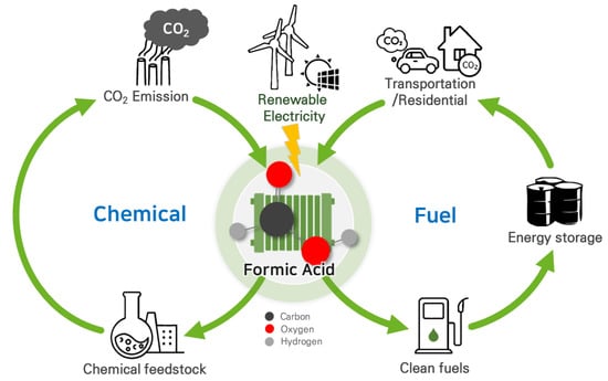
Figure 1. Carbon-neutral cycles of produced formic acid via CO2RR using renewable electricity.
Liquid products such as HCOO−/HCOOH offer significant advantages over gas-phase CO2RR products due to their high energy densities and ease of storage and distribution [13,14]. Formic acid, in particular, is a crucial chemical feedstock with a global production of approximately 800,000 metric tons per year, used in a wide range of applications, including chemical production, cleaning, the textile industry, and antiseptics [15,16,17,18]. Moreover, formic acid has gained attention as a promising hydrogen carrier due to its high volumetric hydrogen density (53 g H2 per liter of HCOOH), low toxicity, and the fact that it is in the liquid phase under ambient conditions [19,20]. It is also considered an energy carrier for fuel cell applications due to its stability, low volatility, and high volumetric capacity [21,22]. Thus, producing formic acid through electrochemical CO2RR can serve as a carbon-neutral liquid fuel, effectively offsetting carbon emissions [23]. However, several challenges must be addressed for the practical applications of CO2RR in renewable formic acid production: (i) improving the selectivity, activity, and durability of the catalysts; (ii) reducing the energy consumption and cost of the process; (iii) scaling up the technology and integrating it with renewable energy sources; (iv) separating the product from aqueous mixture. Additional purification steps are often required, increasing production costs [23,24,25,26].
To address the limitations in CO2RR for formic acid production, extensive research efforts have been focused on developing efficient electrocatalysts, suitable electrolytes, and reactor designs to achieve high productivity. In particular, catalyst development has received significant attention to improving the selectivity and activity toward HCOO−/HCOOH production. Recent studies have made notable progress in identifying and designing efficient electrocatalysts for the selective production of HCOO−/HCOOH. For example, studies on the development of nanostructured and bimetallic catalysts have shown promising results in achieving high selectivity and activity for CO2RR to HCOO−/HCOOH [27,28,29,30,31,32,33,34,35,36]. In addition, single-atom catalysts (SACs) for CO2RR to HCOO−/HCOOH have been investigated due to their high surface area and atomic-level dispersion of active sites, which can enhance their electrocatalytic performance [12].
2. CO2RR to Formate Using CO2-Dissolved Liquid Feed
In early CO2RR studies, numerous research groups have utilized reactors such as 3-electrode and H-type cells to produce formate in aqueous solutions. This type of reactor has been widely employed for investigating various CO2RR catalysts due to its versatile setup. In these experiments, the catholyte is saturated with CO2 by continuous bubbling using a glass sparger before electrolysis. The CO2 gas is supplied continuously to the catholyte throughout the experiment to improve the absorption of the CO2 gas in the aqueous solution [27]. Researchers have utilized this reactor configuration to develop highly active and selective electrocatalysts for CO2RR [27,29,30,31,32,33,34,35,36,40]. Since the previous works by Hori et al. described the classification of metal catalysts according to product selectivity for CO2RR [41], extensive efforts have been made to develop various heterogeneous metal-based catalysts for selective CO2RR to formate. Table 1 summarizes some of the metal catalysts that have been investigated for their potential in CO2RR to formate, including tin (Sn), lead (Pb), bismuth (Bi), and indium (In).
Table 1. Figures of merits of studies reported in the literature for the CO2RR to formate in terms of reactor type, catalysts of the cathode, electrolytes (for 3-electrode cell) or catholyte (for H-type cell), applied potential (vs. reference electrode), faradaic efficiency, and current density for formate production.
| Reactor Type | Cathode | Electrolyte (Catholyte) |
Potential (V vs. RHE) |
FEformate (%) |
jformate (mA cm−2) |
Reference |
|---|---|---|---|---|---|---|
| 3-electrode | Sn/SnO2 porous hollow fiber | 0.1 M KHCO3 | −0.95 | 82.1 | 22.9 | [32] |
| Bi on Cu foil | 0.5 M KHCO3 | −0.86 | 91.3 | 3.08 | [33] | |
| Bi-Sn | 0.1 M KHCO3 | −1.0 | 93.9 | 9.3 | [34] | |
| H-type | Sn-Pb alloy | 0.5 M KHCO3 | −1.36 | 79.8 | 45.7 | [27] |
| SnO2/ZnO hollow nanofiber | 0.1 M KHCO3 | −1.34 | 97.9 | 24.9 | [29] | |
| Pd-Sn alloy/C | 0.5 M KHCO3 | −0.43 | 99.6 | ~2 | [35] | |
| Mesoporous SnO2 | 0.1 M KHCO3 | −1.15 | 75 | 10.8 | [40] | |
| In16Bi84 nano-sphere | 0.5 M KHCO3 | −0.94 | 100 | 14.08 | [30] | |
| AgSn/SnOx (core-shell) | 0.5 M KHCO3 | −0.8 | 80 | 16 | [36] | |
| In-doped SnO2 nanowires | 0.5 M KHCO3 | −1.04 | 82 | 6.02 | [31] |
Choi et al. studied the CO2RR to formate in an aqueous solution using tin–lead (Sn–Pb) alloys [27]. The study found that the Sn56.3Pb43.7 alloy exhibits high faradaic efficiency (FEformate of 79.8%) and current density (jformate of 45.7 mA cm−2) for formate synthesis; 16%, and 25% improved FEformate and jformate compared to the single metal electrodes.
Tan et al. reported a highly efficient CO2RR to formate on a tin (IV) oxide/zinc oxide (SnO2/ZnO) composite electrocatalyst with a grainy hollow nanofiber (HNF) structure [29]. The faradaic efficiency (FE) of formate on the SnO2/ZnO composite HNF reaches as high as 97.9% at −1.34 V (vs. RHE), outperforming many Sn-based catalysts. At −1.54 V (vs. RHE), the SnO2/ZnO HNF exhibits 2 times and 4 times higher current density for formate generation than those of SnO2 HNF and nanoparticles (NPs), respectively. This superior catalytic performance is attributed to its one-dimensional continuous structure as well as to the synergistic effects between SnO2 and ZnO, which facilitate faster electron transfer and improve the conductivity of SnO2/ZnO composite HNF.
Despite these significant results, the kinetics of CO2RR into formate is limited below 50 mA cm−2 (Table 1) due to the polarization losses caused by the low solubility of CO2 in the electrolyte, and the mass transfer limitation of OH− near the electrodes, inevitably limiting the productivity of CO2RR [42]. In particular, the low solubility of CO2 in the aqueous catholyte significantly limits the current density, thus hindering the large-scale application of the CO2RR.
3. CO2RR to Formate Using Gaseous CO2 Feed
There have been experiments in CO2 electroreduction that involve supplying gaseous CO2 to the cathode, allowing for sufficient CO2 delivery to the catalyst even at elevated current densities. Some research groups achieved remarkable improvement in the current density of CO2RR to formate using gas diffusion electrodes (GDEs) typically composed of a backing layer, a microporous layer (MPL), and a catalyst layer (CL) [42,43,44,45]. Several research groups have successfully utilized GDE-type CO2RR reactors (Figure 2a) and achieved high current densities for formate production, exceeding 200 mA cm−2 and even up to 1000 mA cm−2, with faradaic efficiencies (FE) higher than 90% as summarized in Table 2 [46,47,48,49,50,51,52,53]. However, one challenge with GDE-type electrolyzers is that they typically use aqueous electrolytes, such as KHCO3, K2CO3, or KOH, for the collection of liquid products. The presence of these aqueous electrolytes can dilute the liquid products, such as formate/formic acid, which increases the costs associated with product recovery and separation [54].
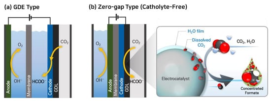
Figure 2. Electrochemical CO2 reduction systems using gaseous CO2 feed: (a) GDE-catholyte type and (b) zero-gap type cells.
Table 2. Figures of merits of studies reported in the literature for the CO2RR to formate in terms of reactor type, catalysts of the cathode, type of membrane, applied reduction potential (vs. RHE) or cell potential, faradaic efficiency, and current density for formate production.
| Reactor Type | Cathode | Membrane | Cathodic Potential/Cell Voltage (V) | FEformate (%) |
jformate (mA cm−2) |
Concentration of HCOO− (wt%) | Reference |
|---|---|---|---|---|---|---|---|
| GDE-catholyte | Bi2O2CO3 nanosheet | Fumasep FAB-PK-130 | −1.55 (vs. RHE) | 93 | 930 | - | [46] |
| InP colloidal quantum dots | AEM | −2.6 (vs. RHE) | 93 | 930 | - | [47] | |
| SnO2 nanosheet | Selemion | −1.13 (vs. RHE) | 94.2 | 471 | - | [48] | |
| Pb powder | - | 4 | 90 | 352 | - | [49] | |
| Bi nanosheet | Nafion® 117 | −1.18 (vs. RHE)/3.1 | 92.4 | 83.2 | 0.204 | [51] | |
| ZnIn2S4 nanosheet | Nafion® 212 | −1.2 (vs. RHE) | 94 | 245 | - | [52] | |
| Bi nanotube | Selemion | −0.56 (vs. RHE) | 98 | 170 | - | [53] | |
| Sn/C | Nafion® 324 | −2.44 (vs. SHE) | 98 | 200 | - | [50] | |
| Zero-gap | Bi/C | Nafion® 117 | 3.1 | 71.7 | 32.3 | 3.39 | [55] |
| Bi/C | Nafion® 117 | 3.0 | 89.2 | 40.1 | 33.7 | [56] | |
| Sn nanoparticle | Nafion® 115 | 2.2 | 93.3 | 51.7 | 4.15 | [54] | |
| Sn nanoparticle | Nafion® 115 | 2.2 | 77.7 | 29.8 | 11.62 | [54] | |
| Bi/C | SustainionTM | 3.6 | 91.6 | 274.8 | 0.67 | [57] |
To overcome this challenge of GDE-type reactors, some research groups have studied CO2RR to formate in a zero-gap type electrolyzer, which eliminates the need for an aqueous electrolyte [54,55,56,57]. Lee et al. reported a facile strategy of catholyte-free electrocatalytic CO2 reduction (CF-CO2R) that avoids the solubility limitation by supplying an appropriate amount of water vapor with gaseous CO2 as a cathode reactant [54]. In this electrolyzer, the water vapor. In the CF-CO2R electrolyzer, water vapor acts as a carrier for supplying dissolved CO2 to the cathode by forming a CO2-saturated aqueous film on the catalyst surface as shown in Figure 2b. The advantage of this approach is that the consumed CO2 in the film can be immediately replenished from the bulk gas stream, enhancing the mass transfer of CO2 and improving the reaction kinetics. Lee et al. achieved a formate current density (jformate) of 51.7 mA cm−2 at a low cell voltage of 2.2 V using this CF-CO2R approach. They also obtained a significantly high concentration of formate solution, reaching 116.2 g-formate L−1, with a formate faradaic efficiency (FEformate) of 77.7% by reducing the vapor supply from 12.58 to 0.65 mg min−1 cm−2 at 2.2 V and 323 K.
The zero-gap electrolyzer has several advantages over the GDE-catholyte method, including (1) lower cell voltage and improved energy efficiency by eliminating a large ohmic resistance of the catholyte compartment; (2) reduced cost by removing the cost of the catholyte; and (3) zero-gap configuration, which makes the system simple and easy to scale up. However, the lower current density observed in this configuration is indeed due to the challenges associated with the discharge of liquid products and the formation of solid precipitates.
In the zero-gap type electrolyzer, the liquid products have to be discharged in the opposite direction of the CO2 supply, and ions (HCOO−, HCO3−, CO32−, K+, and Na+, etc.) in the liquid products form solid precipitates, which limits the supply of CO2. Additionally, the flow of aqueous liquid products through the gas diffusion electrode (GDE) can cause a decrease in the hydrophobicity of the electrode over time, a phenomenon known as electro-wetting. This leads to flooding of GDE that significantly inhibits the migration of CO2 to the catalyst layer, reducing the selective reduction of CO2 to formates while promoting the hydrogen evolution reaction (HER).
Recently, Díaz-Sainz et al. achieved a high jformate of 300 mA cm−2 by continuous operation using an anion exchange membrane (AEM, SustainionTM, Dioxide Materials) with a formate concentration of 6.7 g L−1 at a cell potential of 3.6 V [57]. In this configuration, the formate solution could be obtained at the anode because the HCOO− ions generated in the cathode are transferred to the anode side via the AEM. They even obtained higher jformate up to 600 mA cm−2 with a formate concentration of 10.8 g L−1 at a cell potential of 4.7 V. When AEM is used in a zero-gap type electrolyzer for formate production, the cathodic GDE flooding could be significantly reduced because HCOO− moves to the anode through AEM, and the crossover of water and the migration of cations (K+, Na+, etc.) from the anode is almost completely prevented.
This entry is adapted from the peer-reviewed paper 10.3390/catal13060955
This entry is offline, you can click here to edit this entry!