The efficient management of Data Centers (DCs) is addressed by considering their optimal integration with the electrical, thermal, and IT (Information Technology) networks helping them to meet sustainability objectives and gain primary energy savings. Innovative scenarios are defined for exploiting the DCs electrical, thermal, and workload flexibility, and Information and Communication Technologies (ICT) are proposed and used as enablers for the scenarios’ implementation. The technology and scenarios were evaluated in the context of two operational DCs: a micro DC in Poznan which has on-site renewable sources and a DC in Point Saint Martin.
- data center
- energy efficiency
- heat re-use
- energy flexibility
- workload migration
- evaluation in relevant environment
1. Introduction
As the ICT services industry is blooming, such services being requested in almost every domain or activity, Data Centers (DCs) are constructed and operated to supply the continuous demand of computing resources with high availability. However, this is the nice side of the story, because as this also has an environmental impact, the DCs sector is estimated to consume 1.4% of global electricity [1]. Thus, it is no longer sufficient to address the DCs’ energy efficiency problems from the perspective of decreasing their energy consumption, but new research efforts are aiming to increase the share of renewable energy used for their operation and to manage them for optimal integration with local multi-energy grids [2,3].
Firstly, the DCs are large generators of residual heat that can be recovered and reused in nearby heat grids and offer them a new revenue stream [4]. This is rather challenging due to the continuous hardware upgrades that increase the power density of the chips, leading to an even higher energy demand for the cooling system to eliminate the heat produced by the Information Technology (IT) servers to execute the workload [5]. In addition to the potential hot spots that may endanger the safe equipment operation, other challenges are created by the relatively low temperatures of recovered heat compared with the ones needed to heat up a building and the difficulty of transporting heat over long distances [6,7].
Secondly, the DCs are characterized by flexible energy loads that may be used for assuring a better integration with local smart energy grids by participating in DR programs and delivering ancillary services [8,9]. In this way, the DCs will contribute to the continuity and security of energy supply at affordable costs and grid resilience [10]. Moreover, if renewable energy is not self-consumed locally, problems such as overvoltage or electric equipment damage may appear at a local micro-grid level and could be escalated to higher management levels [11]. To be truly integrated with the grid supply, renewable energy sources (RES), since they are volatile, need flexibility options and DR programs to be put in place [12].
The work presented in this paper contributes to the process of creating the necessary technological infrastructure for establishing active integrative links among DCs and electrical, heat, and IT networks which are currently missing:
-
Defines innovative scenarios for DCs, allowing them to exploit their electrical, thermal, and network connections for trading flexibility as a commodity, aiming to gain primary energy savings and contribute to the local grid sustainability.
-
Describes an architecture and innovative ICT technologies that act as a facilitator for the implementation of the defined scenarios.
-
Presents electrical energy, thermal energy, and IT load migration flexibility results in two pilot data centers, showing the feasibility and improvements brought by the proposed ICT technologies in some of the new scenarios.
2. Scenarios and Technology
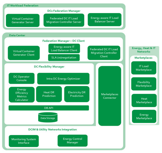
To address this innovative vision, several ICT technologies have been developed and coherently integrated with a framework architecture consisting of three interacting systems (see Figure 1): the DC Flexibility Manager, DCs Federation Manager, Data center infrastructure management (DCIM), and Utility Networks Integration.

Figure 1. Data Centers’ (DCs) optimization framework architecture.
2.1. DC Flexibility Manager System
The DC Flexibility Manager sub-system is responsible for improving DC energy awareness and energy efficiency, by exploiting the internal flexibility for providing energy services to power and heat energy grids. The main components of this sub-system are detailed in Table 1.
Table 1. DC Flexibility Manager components.
| Component | Objective | Relevant Techniques/Technologies |
|---|---|---|
| Intra DC Energy Optimizer | Decides on the optimization action plans that will allow the DC to exploit its latent energy flexibility to provide electricity flexibility services in its micro-grid, to re-use heat in nearby neighborhoods, and finally to leverage on workload reallocation in other DCs as a potential source of additional energy flexibility | Optimization heuristics, DC model simulation |
| Electricity DR Prediction | Predicts the DC energy consumption, generation, and flexibility using the following time windows: day ahead (24 h ahead), intraday (4 h ahead), and near real-time (1 h ahead). | Machine learning-based models |
| Heat DR Prediction | Predicts heat available to be re-used in nearby neighborhoods. Estimates the temperature of the hot air recovered by the heat pumps from the server room in various configurations and uses the data to train Multi-Layer Perceptron prediction model. | Computational Fluid Dynamics, Neural Networks |
| Efficiency Metrics Calculator | Calculates different metrics in close relation with decided optimization plans aiming to assess their impact on the DC operation. Examples of metrics used: Adaptability Power Curve at RES, Data Centre Adapt, Grid Utilization Factor, Energy Reuse Factor, etc. | |
| Data Storage | Stores the DC main sub-system characteristics, thermal and energy monitored data, prediction outcomes, and optimization action plans. | NoSQL database |
| DC Operator Console | Displays information on the monitoring, forecasting as well as on flexibility optimization decision making. It allows the DC operator to select and validate an optimization plan and to configure the DC optimization strategies. | React JavaScript library |
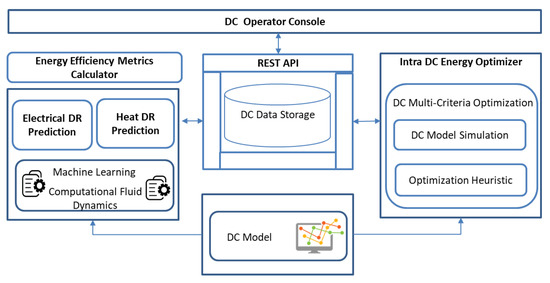
The interaction between the DC Flexibility Manager system components is presented in Figure 2. The Intra DC Energy Optimizer component takes as input the thermal and electrical energy predictions determined by the Electricity and Heat DR Prediction components as well as the DC model describing the characteristics and operation. Its main output is the optimal flexibility shifting action plan, whereby the DC energy profile is adapted to provide various services in the Electrical and Heat Marketplaces. The Energy Efficiency Metrics Calculator estimates the values of the metrics and the optimization action plans are displayed on the DC Operator Console for validation. If the plan is validated by the operator, its actions will be executed.

Figure 2. DC Flexibility Manager System architecture.
2.2. DCs Federation Manager
DCs Federation Manager is responsible for orchestrating the workload relocation among federated DCs. Table 2 describes the main components of this system.
Table 2. DCs Federation Manager components.
| Component | Objective | Relevant Techniques |
|---|---|---|
| Energy-Aware IT Load Balancer | Decides on the optimal IT loads placement across the federation in DCs offering capacity in the most efficient or greenway. It defines the actual IT loads relocation plan based on the capacity offers and bids of other DCs to ensure the implementation of following the renewable energy or minimum energy price strategies. | Knapsack algorithm, Branch and Bound techniques |
| Federated DC IT Load Migration Controller | Performs the actual live IT load migration between federated DCs, which belong to different administrative domains ensuring almost zero downtime. | Live migration of VMs |
| Virtual Container Generator | A distributed (reversed client-server model) component responsible for tracking information related to the lifetime of IT virtual loads, that is virtual machines or containers, on the blockchain, effectively transforming them into virtual containers (VCs). | Blockchain for IT load traceability |
| SLA (re)negotiation | Responsible for monitoring the SLA compliance of the CATALYST VCs, based on the events registered in the VCG. SLARC operation is based on the notion of Service Level Objectives (SLOs) referring to leveled acceptable behavior against a target objective for given periods. SLARC would notify registered parties prior to SLA breakage. | Blockchain, Publish/Subscribe mechanisms |
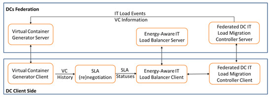
The Federated DC MIgration Controller (DCMC) [14], including Master and Lite Client and Server, enables the live migration of IT load among different administrative domains, without affecting the end-users’ accounting and without service interruption (see Figure 3). The secure communication channels between DCs are deployed by the DCMC through OpenVPN and secured by Oauth2.0 to ensure secure and authorized transfers. A new VM in the form of a virtual compute node gets created in an OpenStack environment of the destination DC to host the migrated load at the destination, while tokens for authenticating the DCMC components are retrieved via an integrated KeyCloak server (part of DCMC software). The DCMC software can attach the new virtual compute to the source DC’s OpenStack installation, which means that the source DC is the sole owner/manager of the load even albeit in a different administrative domain.

Figure 3. DCMC architecture.
In detail, the DC IT Load Migration Controller clients will receive migration offers or bids requests by the Energy-aware IT Load Balancer, originally spurred by the Intra DC Energy Optimizer. The DC IT Load Migration Controller client will also inform the Energy-Aware Load Balancer of potential rejection or acceptance. Upon acceptance of the migration bid/offer, DC IT Load Migration Controller clients will inform the DC IT Load Migration Controller server that they are ready for migration; in case of a migration bid, the DC IT Load Migration Controller client will first set up the virtual compute node to host the migrated load. Then, DC IT Load Migration Controller server is responsible for setting up a secure communication channel between the two DCs: the source and the destination of the IT load. After communication is set up and the source DC is connected to the virtual compute node at the destination DC, the migration starts. Then, the DC IT Load Migration Controller clients inform both the Energy-Aware IT Load Balancer about the success or failure of the migration.
Under a federated DCs perspective, the Virtual Container Generator enables IT loads trackability and allows for indisputable SLA monitoring. In short, the Virtual Container Generator client will offer information related to the lifetime of the VCs, which will first be translated by the SLA (re)negotiation component into service license objective (SLO) events and second into SLA status compliance. This information will be fed to the Energy-Aware IT Load Balancer component so that effective decisions on Virtual Container load migrations may be achieved. The SLA (re)negotiation component features two methods of information retrieval, which are RESTful and publish-subscribe, while for data feeding, pull requests towards the Virtual Container Generator will be performed.
2.3. DCIM and Utility Networks Integration
This system offers different components for allowing integration with existing Data center infrastructure management software or with the utility networks considered for flexibility exploitation: electricity, heat, and IT.
The Marketplace Connector acts as a mediator between the DC and the potential Marketplaces that are set up and running and on which the DC may participate. Through the Marketplace Connector, a DC can provide flexibility services, trade electrical or thermal energy, and IT workload. Additionally, it provides an interface, and the electricity or energy grid operators are responsible for listening after Demand Response (DR) signals sent by the Distribution System Operator for reducing the DC energy consumption at critical times or for providing heat to the District Heating network. The DR request is forwarded to the Intra DC Energy Optimizer, which evaluates the possibility for the DC to opt in the request based on the optimization criteria.
Energy Control Manager interfaces the DC appliances and local RES via existing DC infrastructure management system (DCIM), or other control systems (e.g., OPC server), implements, and executes the optimization action plans.
The Monitoring System Interface interacts with existing monitoring systems already installed in a DC, adapts the monitoring data received periodically and provides this data to the Data Storage component from which it will be analyzed in the flexibility optimization processes.
3. DC Pilots and Results
The proposed technology has been validated throughout the first four scenarios defined in Table 3 in two pilots DCs, a Micro Cloud DC connected to PV system and located in Poznan Poland, and a Colocation DC located in Pont Saint Martin, Italy. The selection of the scenarios to be evaluated was driven by the hardware characteristics of the considered pilots DCs, their type, and sources of flexibility available. For the real experiments, relevant measurements were taken from the pilot DCs, flexibility actions were computed by the software stack deployed in the pilot and the actions were executed by leveraging on the integration with existing DCIM. Finally, relevant KPIs were computed to determine the energy savings and thermal and electrical energy flexibility committed. The KPIs were calculated exclusively, considering the monitored data reported in the experiment, and no financial or energetic parameters were assumed.
Table 3. New DCs energy efficiency scenarios.
| Scenario | Optimization Objectives | Utility Network |
| Scenario 1: Single DC Providing Electrical Energy Flexibility | Optimize the DC operation to deliver energy flexibility services to the surrounding electrical energy grids ecosystems aiming to create new income sources and reduce DC energy costs. Assess resiliency of energy supply and flexibility, against adverse climatic events or abnormal demand, trading off DC assets energy generation or consumption against on-site or distributed RES, energy storage, and efficiency. | Electrical Energy Network |
| Scenario 2: Single DC Providing Heat | Optimize DC operations to deliver heat to the local heat grid. Recover, redistribute, and reuse DC residual heat for building space heating (residential and non-residential such as hospitals, hotels, greenhouses, and pools), service hot water, and industrial processes. The DC achieves significant energy & cost savings, reduces its CO2 emissions, contributes to reducing the system-level environmental footprint, and supports smart city urbanization. | Thermal Energy Network |
| Scenario 3: Workload Federated DCs | Exploit migration of traceable ICT-load between federated DCs, to match the IT load demands with time-varying on-site RES availability (including Utility/non-utility owned legacy assets) thus reducing the operational costs and increasing the share of renewable energy used. | IT Data Network |
| Scenario 4: Single DC Providing both Electrical Energy Flexibility and Heat | Optimize the DC operation to deliver both electrical energy flexibility services and heat to the surrounding energy (power and heat) grids ecosystems. The DC will act as a converter between electrical and thermal energy and vice versa to gain extra revenue on top of normal operation. | Electrical Energy &Thermal Energy Networks |
| Scenario 5: Workload Federated DCs Providing Electrical Energy Flexibility | Exploit migration of traceable ICT-load between federated DCs to deliver energy flexibility services to the surrounding power grids ecosystems aiming to increase DC income for trading flexibility. | Electrical Energy & IT Data Networks |
| Scenario 6: Workload Federated DCs Providing Heat | Exploit migration of traceable ICT-load between federated DCs to deliver heat to their local heat grids aiming to increase the revenue for the reuse of their residual heat. | Thermal Energy & IT Data Networks |
| Scenario 7: Workload Federated DCs Providing Both Thermal and Electrical Energy Flexibility | Exploit migration of traceable ICT-load between federated DCs to deliver: (i) heat to the surrounding thermal grids and (ii) energy flexibility to the surrounding power grids. | Electrical Energy & Thermal Energy & IT Data Networks |
4. Conclusions
To provide a guideline on the use of proposed ICT theology and applicability of the specific scenarios and flexibility actions, Table 4 shows that they fit different DC types. We used a DCs’ well-known classification according to their specific operation, such as collocation, cloud, and High-Performance Computing (HPC). For each DC type, we highlighted the possibility of applying a specific scenario considering their resources and flexibility sources.
Table 4. Suitability of specific scenarios and flexibility for data center types (+ suitable, - not suitable).
| Scenarios | Data Center Type | |||
|---|---|---|---|---|
| No. | Flexibility Source | Colocation | Cloud | HPC |
| 1 | Delay-tolerant workload shifting | - | + | + |
| Use of cooling inertia | + | + | + | |
| Use of RES and energy storage | + | + | + | |
| Use of diesel generators | + | + | + | |
| 2 | Local heat re-use | + | + | + |
| Heat re-use at external entities | + | + | + | |
| 3 | IT load migration | - | + | - |
| 4 | Dynamic usage of the cooling system and shifting of delay-tolerant workload | - | + | - |
| 5 | IT load migration based on optimal DC power usage levels | - | + | - |
| 6 | IT load migration + heat re-use | - | + | - |
| 7 | IT load migration with energy flexibility and heat re-use | - | + | - |
Generally, cloud DCs are suitable for most scenarios due to their flexibility, moderate utilization, and good control. Of course, these are general guidelines and suitability depends strongly on a specific case, e.g., used software and technologies, data center policies, customers’ requirements, etc. However, flexibility actions based on managing the workload are not well suited to collocation DCs that do not have direct control on servers and running workloads.
This entry is adapted from the peer-reviewed paper 10.3390/su12239893
