Your browser does not fully support modern features. Please upgrade for a smoother experience.
Please note this is an old version of this entry, which may differ significantly from the current revision.
Subjects:
Remote Sensing
Lava tubes are tunnel–like structures within lava flows and can vary in diameter, length, and shape. Due to the Moon and Mars both having low–gravity environments, the lava tubes on these celestial bodies can have volumes that are 1–3 orders of magnitude larger than those found on Earth.
- planetary radar
- lava tubes
- the Moon
- Mars
- subsurface structure
1. Introduction
In recent years, the Moon and Mars have been popular celestial bodies for human deep space exploration. Over a hundred exploration missions have been conducted for the Moon and Mars [1,2,3]. In general, the exploration modes for the Moon and Mars can be divided into orbiter missions and in situ lander or rover missions. Significant scientific achievements have been made in the study of the shallow subsurface structure, material composition, terrain, and landforms of the Moon and Mars through these exploration modes [1,4,5,6,7].
Studying the internal structure of these lava tubes and their distribution in the shallow subsurface of celestial bodies has always been challenging. However, with the development of modern radar technology in the past 30 years, ground penetrating radar (GPR) have gradually become the most effective technology for investigating the subsurface structures of celestial bodies. This has been successfully applied in exploring the shallow subsurface of the Moon and Mars. For example, the Chang’e–3 and Chang’e–4 missions to the Moon carried Moon–based GPR, and the Mars exploration missions, Tianwen–1 and Perseverance, carried RoSPR and RIMFAX radar [7,10,11,12,13,14,15,16]. The GPR emits electromagnetic pulse signals from its transmitting antenna. These signals encounter different geological layers beneath the surfaces of celestial bodies and produce reflected echoes due to differences in dielectric constants. The echoes are received by the receiving antenna, providing information on various geological layers and underground structures [1,11,17]. By analyzing the electromagnetic characteristics of the radar echoes and underground structure information, it is hoped that we can locate the position of the lava tubes beneath the surfaces of the Moon and Mars, as well as obtain their physical morphology and size [18]. For example, based on Lunar Radar Sounder (LRS) data, Kaku et al. [19] provided the first evidence of intact buried lava tubes beneath the surface in the Marius Hills region of the Moon. Ding et al. [7] first reported the existence of a buried underground cavity structure with a height of approximately 3.1 m beneath the Chang’e–3 landing area using the Moon–based GPR onboard the Chang’e–3 rover. Due to the frequent volcanic activity and impact events that both the Moon and Mars experienced in their history [20,21,22], a large number of unobserved lava tubes and cavities are expected to exist beneath the surfaces of these celestial bodies [7,8,23]. These subsurface spaces can provide important references for selecting future lunar and Martian base sites [24,25]. Lava tubes can provide natural shelters or serve as essential spaces for human–built habitats on these planets [26]. Inside these tubes, artificial habitats can be constructed, creating conditions for achieving self–sufficiency in essential resources such as oxygen, water, and food for humans on these planets in the future [27].
2. Mechanisms of Lava Tube Formation on the Moon and Mars
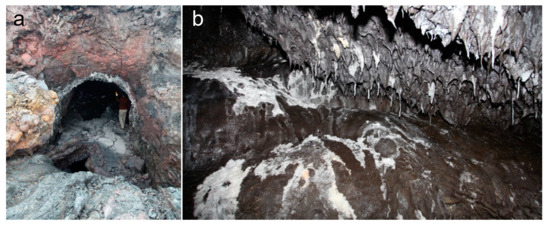
Lava tubes are special underground cavities formed during volcanic eruptions from flowing lava. The formation process of lava tubes involves the eruption of magma deep within the celestial bodies. Lava tubes form when a lava flow advances across the ground, the top and sides freeze, and the molten interior drains out [28]. Due to the extremely high temperature inside the lava flow and cooler temperatures in the surrounding environment, the outer layer of the lava cools and solidifies. Under the insulating effect of the hard outer shell, the inner lava remains hot and continues to flow. As time passes, the solidified walls of lava slowly thicken. At the same time, the top of the tube becomes stable, thus creating a tubular passage underground. The lava flow stops when the eruption ends, and the lava inside the tube flows out, ultimately forming a lava tube [8,23,29]. Figure 1 illustrates a lava tube formed during the Tolbachik volcanic eruption.
Lava tubes can become buried beneath the surface due to several natural long–term geophysical processes. One of the reasons is volcanic activity. As new eruptions arise, the resultant lava flows can accumulate and eventually submerge pre–existing formations. Another contributing factor is tectonic activity, including seismic vibrations and earth crustal displacement, capable of inducing displacement on the earth’s surface and concealing surface structures. The effects of meteorite impacts, specifically sputtering, may also induce lava tube burial. Given an adequate timescale, lava tubes can become buried and preserved beneath layers of sediment and rock.
Two solidification mechanisms are typically present in lava tubes on the Moon and Mars: the inflation and roofing of a channel [8,29,31]. The inflation mechanism of lava tubes usually occurs in slow–moving lava flows, often as pahoehoe lava. Pahoehoe lava flows are characterized by their slow speed and relatively low viscosity, resulting in a rope–like appearance [32]. During the process of inflation, the pahoehoe lava flow expands and forces the crust to break [33]. The pieces of crust form the support of the lava tube and eventually create a hollow tube [8,29]. In this mechanism, the outer shell of the lava tube’s surface essentially cools and solidifies in situ [29]. Lava tubes originating by roofing arise through several formation mechanisms. Crust formation along channel edges via cooling can result in solidification, which subsequently progresses downstream in a V–shape [8,29,34]. This creates a “zippering” effect over the channel. Another mechanism is in channels with stable flow, the surface develops a scum or crust that thickens either through the periodic overflow of lava or cooling on the underside of the layer [29,34]. This thickening results in the structure becoming stable. A similar mechanism whereby a roof is constructed from previously solidified crustal plates that have broken loose and been carried downstream also occurs. These plates fuse to the channel sides and to each other, forming the roof of the channel. Finally, more turbulent lava flows can result in the formation of lava tubes through splashing, spattering, and lava overflow, which create levees along the edges of the channel. These levees eventually congregate in an arch over the channel and fuse together to form the lava tube roof [8,29,34].
Despite the similarities in the lava tube formation mechanism between the Moon, Mars, and Earth, significant differences could exist in the volume and length of lava tubes due to factors such as the low–gravity environment of these planetary bodies. The surface gravity environment of a planet can influence the maximum theoretical size of lava tubes. Given the surface gravity of Mars, which is approximately one–third of Earth’s gravity, and the Moon, which is even less at approximately one–sixth of Earth’s gravity, the formation of large–scale lava tubes is facilitated to a greater extent compared to Earth. On Earth, the diameter of lava tubes usually ranges from several meters to several tens of meters. On Mars, it could extend to several hundreds of meters, and on the Moon, the diameter of lava tubes could reach up to several kilometers. Overall, the volume of lava tubes on Mars may be about ten times that on Earth, while on the Moon, it is even larger, up to over a thousand times that on Earth [8,18,35].
3. The Principle of GPR to Detect Lava Tubes
Because lava tubes on the Moon and Mars are usually buried beneath the surface, the penetrating feature of radar makes it an excellent tool for observing subsurface lava tubes. GPR is a device mainly employed on Earth, which utilizes electromagnetic waves to determine the distribution of subsurface materials [36,37]. Radar is a geophysical method. Its principle of operation is as follows: the radar transmitter generates a carrier–free microsecond pulse, which is then radiated or coupled to the planetary surface through the transmitting antenna. When the signal propagates in the subsurface medium, if it encounters non–uniform media or different interfaces, it will generate signals reflected and scattered by electromagnetic waves. After the receiving antenna of the radar receives the reflected and scattered signals, corresponding detection data are obtained through processes such as amplification and the sampling of the receiver. By analyzing, processing, and imaging the detection data, the distribution characteristics of subsurface structures, such as the position, shape, and depth parameters of subsurface materials, can be obtained [7,37].
3.1. Orbiting Radar Sounders
Orbiting radar are carried by spacecraft and launched into orbit by a rocket to observe and survey the planetary surface while orbiting around the target planet. This type of radar has high resolution, large coverage area, and a high signal–to–noise ratio, which can quickly obtain shallow subsurface radar images of the target planet [1]. However, this technology is expensive in terms of cost.
In 1972, the Apollo Lunar Sounder Experiment (ALSE) was carried out on the Apollo 17 mission to the Moon to detect electromagnetic discontinuities beneath the lunar surface, revealing underground geological structures [38]. The preliminary experimental results show that the radar successfully detected the features of the lunar surface and subsurface structures, such as rifts, faults, and volcanic flows [38,39], providing valuable experience and technology for the application of radar systems in planetary resource surveys in the future.
In 2007, the Japanese Selenological and Engineering Explorer (SELENE) carried the LRS, which can penetrate deeper into the subsurface compared to ALSE and reach depths of several kilometers [40]. In addition, LRS uses frequency modulation technology to improve distance resolution and distinguish the strength difference between the surface echo and subsurface echo. LRS is the second attempt to use radar sounders to explore the subsurface of the Moon after ALSE. The basic parameters of these two radar sounders are shown in Table 1, and the conceptual diagram can be seen in Figure 2.
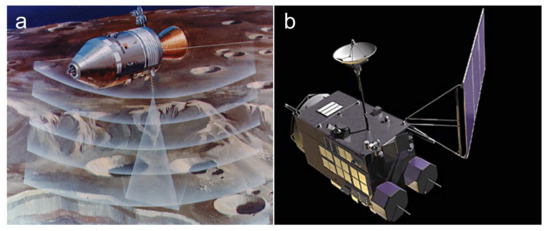
Figure 2. Schematic diagrams of spacecraft detection on the Moon, which carry orbiting radar sounders. (a) ALSE onboard the Apollo 17 mission detecting the lunar surface (Credit: NASA/SCIENCE PHOTO LIBRARY). (b) Lunar Radar Sounder onboard SELENE mission [41].
| Radar | ALSE | LRS | ||
|---|---|---|---|---|
| Orbiter | Apollo 17 | SELENE | ||
| Launch year | 1972 | 2007 | ||
| Status | HF1 11 | HF2 22 | VHF 33 | – |
| Wavelength (m) | 60 | 20 | 2 | 60 |
| Center frequency (MHz) | 5.266 | 15.8 | 158 | 5 44 |
| Detection depth (m) | 1300 | 800 | 160 | 5000 |
| Vertical resolution (m) | 300 | 100 | 10 | 75 |
| Power (w) | 130 | 118 | 95 | 800 |
11 Channel 1 of high frequency. 22 Channel 2 of high frequency. 33 Very high frequency. 44 LRS is available in 1 MHz and 15 MHz optional.
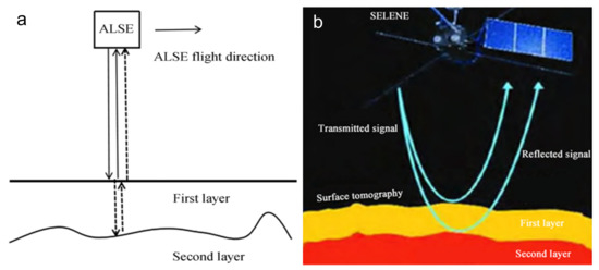
The operating principle of the ALSE and LRS (shown in Figure 3) is the same. The electromagnetic pulse transmitted by the radar antenna penetrates the lunar surface and subsurface. When the pulse encounters a boundary with a discontinuity in dielectric constant, such as the lunar surface or subsurface layer, it generates an echo signal that is received by the radar receiving antenna. Compared to the potential diameter of lunar lava tubes, which can be in the order of kilometers, the signal wavelength is in the order of meters. Therefore, this technology is particularly suitable for detecting the existence of large lava tubes beneath the lunar surface [19,42].
ALSE and LRS were not explicitly designed for detecting lava tubes. However, Kaku et al. [19] utilized data from LRS and found several locations on the Moon with unique echo patterns, suggesting the existence of intact lava tubes beneath those areas. Some of the detected areas were consistent with the results of gravity data from the Gravity Recovery and Interior Laboratory (GRAIL) vehicle mission, which also supported the presence of underground cavities consistent with very large lava tubes [45]. GRAIL was a dual–spacecraft mission to explore the surface and internal gravitational variations on the Moon. By analyzing GRAIL data, scientists could create high–resolution models of the lunar gravity field, revealing information about the Moon’s structure, composition, and evolution [46]. Therefore, GRAIL helps identify mass–deficit areas and assists in detecting lava tubes. Kaku’s research confirms the feasibility of using lunar orbiting radar sounders to detect lava tubes [19].
LRS has a larger detection depth but a lower center frequency, which results in a lower vertical resolution (75 m at free space), making it only suitable for detecting larger lava tubes. It is not suitable for detecting smaller–scale lava tubes. Kobayashi et al. [47] inferred that LRS has the potential to image shallow lava tubes. To better utilize the lava tube resources on the Moon, Sood et al. [48] proposed the design of high–frequency orbiting radar sounders for detecting shallow and small–scale lava tubes. They suggested using GRAIL gravity data analysis to locate potential volcanic tube candidate regions and develop a satellite with high–frequency radar detection instruments. The satellite would fly between 10 and 20 km above the Moon’s surface and determine whether there are hollow structures several meters to several kilometers beneath the lunar surface. In addition, the detection results could be compared with the known location of skylights on the lunar surface to validate the existence and size of the lava tubes.
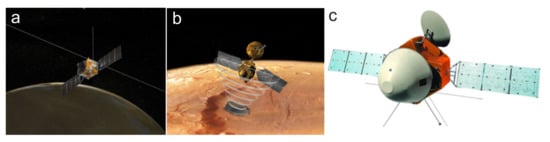
Currently, the Mars Express mission of the European Space Agency is equipped with Mars Advanced Radar for Subsurface and Ionosphere Sounding (MARSIS), and the Mars Reconnaissance Orbiter mission carries SHARAD (Shallow Radar). The Tianwen–1 orbiter is equipped with Mars Orbiter Subsurface Investigation Radar (MOSIR), all successfully operated in the Mars orbit. The basic parameters of these radars are detailed in Table 2, and their conceptual diagrams can be found in Figure 4.
| Radar | MARSIS | SHARAD | MOSIR |
|---|---|---|---|
| Orbiter | Mars Express | Mars Reconnaissance | Tianwen–1 |
| Launch year | 2005 | 2006 | 2020 |
| Orbital altitude (km) | 250–900 | 250–300 | 265 |
| Center frequency (MHz) | 1.3–5.5 | 15–25 | LF: 10–20 HF: 30–50 |
| Detection depth (km) | 0.5–5 | 0.1–1 | 0.1–1 |
| Vertical resolution (m) | 150 | 15 | 30(LF)/7.5(HF) |
| Power (W) | 10 | 10 | ≥100 |
MARSIS was the first spacecraft–borne radar designed to detect subsurface objects on Mars [49]. The main scientific goal of MARSIS is to map the distribution of solid and liquid water in the upper crust of Mars. This radar is a dual–channel low–frequency detector, which operates between 1.3 and 5.5 MHz for underground exploration. The wavelength for underground detection is between 60 and 160 m, and it can detect geological structures up to 5 km below the upper crust of Mars [49]. Since August 2005, MARSIS has been collecting data on Mars and transmitting information to Earth.
SHARAD is a high–frequency spacecraft–borne exploration radar provided by the Italian Space Agency (ASI) for NASA’s Mars Reconnaissance Orbiter (MRO) mission. Its design goal is similar to that of MARSIS, which aims to map the upper 1 km of Mars’ surface and detect water and ice underground [53,54]. Unlike MARSIS, however, SHARAD uses a center frequency of up to 20 MHz and sacrifices the penetration depth for a finer vertical resolution, thereby obtaining subsurface radar images of Mars with a vertical resolution of approximately 15 m [15]. They complement each other, with SHARAD providing high–resolution images and MARSIS providing a high–penetration depth and low–resolution images.
In 2020, the Tianwen–1 mission carried MOSIR to Mars. The design of MOSIR aims to use cross–polarization radar echoes to detect surface and subsurface structures on Mars [51,55]. The radar uses low–frequency and high–frequency channels, which allow it to detect depths of over 100 m and produce high–resolution subsurface radar images of Mars [52,56]. MOSIR can achieve cross–polarization radar echoes, which can enhance the detection of underground interfaces and structures with different dielectric properties, thus supplementing the detection results of MARSIS and SHARAD. MOSIR works with the Mars Rover Subsurface Penetrating Radar (RoSPR) released by Tianwen–1 for the detailed on–site investigations of the landing area and other selected regions.
3.2. In Situ Ground Penetrating Radar
In situ GPR refers to a radar sent to the planet’s surface via rocket launch for on–site exploration. The general working principle of this type of radar [1,11] is to generate ultra–wideband unmodulated picosecond pulses through the transmitter, radiate the pulses towards the planet’s surface through the transmitting antenna, and couple the ultra–wideband electromagnetic pulse signal to the surface. During the signal propagation, if there are variations such as non–uniform layers, interfaces of different media, or lava tubes, the signal will produce the reflection, transmission, and scattering phenomena of electromagnetic waves. The receiving antenna receives the reflected and scattered signals, and the corresponding detection data are obtained after being amplified and sampled by the receiver. By analyzing, processing, and imaging the data, evidence of the lava tubes can be obtained, thereby determining the location of the lava tubes on the exploration route of the rover.
The Moon–based GPR can achieve high–precision subsurface geological structure and regolith thickness detection and has a higher resolution than orbiting radar sounders [18,57]. Therefore, this technology is expected to become one of the essential tools for lava tube detection and exploration. However, the limitation of this technology is that its detection area is limited compared to an orbiter.
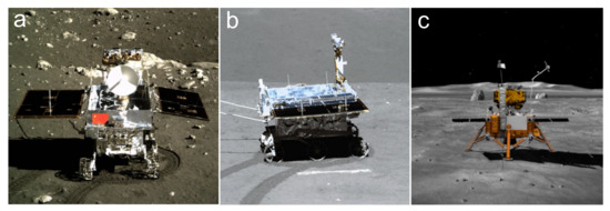
The Chang’e–3 spacecraft was the first spacecraft to achieve a soft landing on the Moon since the Soviet spacecraft Luna 24 in 1976 [58]. Since the successful landing of the Chang’e–3 lunar mission carrying GPR in 2013, three missions, including Chang’e–3 (CE–3), Chang’e–4 (CE–4), and Chang’e–5 (CE–5), have used GPR for lunar subsurface exploration [59,60,61]. Figure 5 shows the corresponding equipment carried by these missions. The basic parameters of these radars are listed in Table 3. Among them, the radars carried by CE–3 and CE–4 are the same and use single–antenna radar [62]. The difference between CE–4 and CE–3 is that CE–3 landed on the nearside of the Moon, while CE–4 landed on the far side of the Moon [63]. In addition, the CE–5 mission carried the Lunar Regolith Penetrating Radar. This radar uses an ultra–wideband (UWB) array imaging technology and innovatively designed multiple antenna arrays to obtain the high–resolution (5 cm) imaging results of lunar rock layers [64,65]. However, the CE–5 radar was fixed to the lander, assisting in the drilling and sampling process without moving.
| Mission | CE–3/4 | CE–5 | CE–7 𝟏1 | ||
|---|---|---|---|---|---|
| Launch year | 2013/2018 | 2020 | 2026 (est.) | ||
| Status | LF | HF | – | LF | HF |
| Center frequency (MHz) | 60 | 500 | 2000 | 60 | 800 |
| Detection depth (m) | ≥100 | ≤30 | ≥2 | ≥400 | ≥40 |
| Thickness resolution (m) | Meter–sized | 0.3 | Centimeter–sized | 2 | 0.15 |
11 The parameters of the CE–7 lunar radar are from the China Lunar Exploration and Space Engineering Center (CLEP) bidding requirements.
In the future, China will launch its Chang’e–7 (CE–7) lunar probe [13]. It is expected to carry a multi–polarized and single–polarized detection functional lunar radar. The CE–7 lunar radar payload aims to determine the shallow characteristics of the lunar surface to detect the thickness, water ice, and layering structure of the lunar regolith, providing a scientific basis for the study of the shallow lunar structure. Furthermore, it is also expected to be used for detecting geological features, such as lava tubes, under the lunar surface [69]. Table 3 presents basic information about the CE–3, CE–4, CE–5 and CE–7 lunar probes.
Currently, the subsurface structures of Mars have been probed using the Radar Imager for Mars’ subsurface experiment (RIMFAX) launched by NASA and the Mars Rover Penetrating Radar (RoPeR) launched by the China National Space Administration [12,74]. In the future, the European Space Agency (ESA) plans to launch the Water Ice and Subsurface Deposit Observation on Mars (WISDOM) in 2028 to explore the subsurface of Mars. The basic parameters of these radar systems are shown in Table 4 and the Images of rovers are shown in Figure 6. It has been determined that there are a total of 272 cones present within the site RoPeR [75]. It is believed that the rootless cones developed from explosive interactions between surficial lavas and surface groundwater [76,77,78], which can be considered since the site RoPeR probably had volcanic activities in the past. The location chosen for the WISDOM landing site was Oxia Planum, which features a mafic composition, a massive appearance, and a resistance to erosion [79]. These characteristics indicate the possibility of explosive deposits or lava flows being present in the area [79]. These Martian GPRs have the potential to detect subsurface structures such as lava tubes or voids up to a depth of a few hundred meters beneath the Martian surface.
| Radar | RIMFAX | RoPeR | WISDOM | ||
|---|---|---|---|---|---|
| Rover | Perseverance | Zhurong | ExoMars | ||
| Launch Year | 2020 | 2020 | 2028 (est.) | ||
| Status | LF | HF | LF | HF | – |
| Center frequency (MHz) | 375 | 675 | 55 | 1300 | 1750 |
| Detection depth (m) | ≥10 | ≥10 | ≥3 | 3–10 | |
| Thickness resolution (cm) | 10–20 | 20–40 | Meter–sized | Centimeter–sized | 3 |
RIMFAX is a GPR deployed on the Perseverance rover during the Mars 2020 mission, and it was the first ground–based radar used for subsurface exploration on Mars [12]. Compared to orbital radar such as SHARAD or MARSIS, RIMFAX employs stepped frequency continuous wave (SFCW) technology that covers a wider frequency range (150–1200 MHz) with a high dynamic range and broad bandwidth. This technology increases the penetration depth into the Martian soil, resulting in high–resolution and high–sensitivity data, which is complementary to other instruments measuring surface properties or deeper layers. It can thus be used to locate the positions of lava tubes [81].
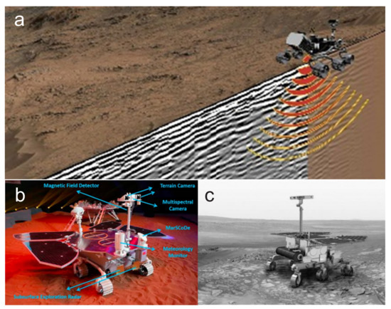
Figure 6. Images of the rovers, including Perseverance, Zhurong, and ExoMars. (a) Scene of Perseverance driving on the surface of Mars, including the transmission of radar waves towards the subsurface by RIMFAX and the visualization of underground topography and stratigraphic structures [12]. (b) Model of the Zhurong [82]. (c) Image of the ExoMars [83].
RoPeR is a GPR launched along with the Tianwen–1 spacecraft in the same year as the Perseverance rover. Similarly to WISDOM, which will be carried by the ExoMars rover in the future, RoPeR collects data using complete polarization to explore the subsurface structure of Mars and detect the presence of water and ice beneath the Martian surface [74,84]. The complete polarization radar employs four antennas, and the polarization rotation properties of the subsurface can be measured by analyzing the data relationships between antenna combinations [85]. Full–polarization radar has been used on Earth to identify subsurface anomalies, such as cracks and pipelines [86,87]. By utilizing the polarization properties of RoPeR and future WISDOM, it is hoped that features such as lava tubes or cavities beneath the surface of Mars will be detected from multiple perspectives.
RoPeR and WISDOM utilize a polarization–sampling mode to detect subsurface water ice [84]. Under specific conditions, water ice can generate a coherent backscattering effect [88], which results in abnormally high–intensity radar signals and a high circular polarization ratio (CPR) [89]. Besides detecting water ice, studies have also found that geological targets, such as lava flows, rock surfaces, and lunar impact crater deposits can produce a high CPR, which deserves further exploration. Therefore, RoPeR and WISDOM could potentially use CPR to further investigate lava tubes.
This entry is adapted from the peer-reviewed paper 10.3390/rs15112850
This entry is offline, you can click here to edit this entry!