Your browser does not fully support modern features. Please upgrade for a smoother experience.
Please note this is an old version of this entry, which may differ significantly from the current revision.
Subjects:
Engineering, Civil
Carbon emission is an important index to evaluate the green degree. To quantify carbon emissions, Life Cycle Assessment (LCA) is a widely used method. It divides the cycle into six stages: raw material acquisition, material processing, component production, construction, building operation and maintenance, and demolition. Especially for the bridge demolition stage, a decisive factor in the carbon emission quantity is the demolition method. A demolition scheme of "Self-propelled modular transporter (SPMT) technology + large segment cutting" is proposed with low carbon emission, high efficiency and safety.
- demolition of existing bridge
- life cycle assessment
- SPMT
1. Introduction
During the process of rapid development of urban transportation, it is inevitable that some existing bridges will need to be demolished. Environmental protection is currently a major concern, and carbon emissions are closely related. The International Energy Agency (IEA) released the Report of CO2 Emissions in 2022 [1], which pointed out the severe situation of carbon emissions. Furthermore, buildings and construction account for 40% of all emissions [2]. In addition, bridge demolition is essentially the reverse process of its construction; with the multiple system transformations, structural stress changes need to be considered [3]. In recent years, the demand for demolishing existing bridges has shown an increasing trend, and demolition is required to be green, rapid, and safe.
Carbon emission is an important index to evaluate the green degree. To quantify carbon emissions, Life Cycle Assessment (LCA) is a widely used method [4]. It divides the cycle into six stages: raw material acquisition, material processing, component production, construction, building operation and maintenance, and demolition. Especially for the bridge demolition stage, a decisive factor in the carbon emission quantity is the demolition method [5]. Recently, various demolition methods have been proposed and applied, from blasting to static cutting, gradually reducing the impact on the environment. As a result, low-carbon, green, and harmless demolition methods have become a trend.
On the other hand, existing bridges have structural damage to the extent that the strength, stiffness, and bearing capacity have been reduced as a result of the deterioration of structural material, concrete shrinkage and creep, fatigue, corrosion of steel, relaxation of the prestressed tendon, and environmental influence [6,7,8]. Therefore, ensuring safety during the demolition is an essential issue. Comprehensive consideration of various practical factors to determine a reasonable demolition scheme is an important requirement for achieving green, safe, and rapid demolition.
For bridge demolition cases, safety accidents have occurred frequently due to insufficient consideration of factors that affect the safety of bridge demolition. For example, in 2004, for the demolition of the continuous steel box girder of the Sikorsky Bridge in the United States, the crane overturned [9]. In 2016, for the demolition of the Taihe Bridge in Jiangxi, China, the improper demolition of arches led to its collapse [10]. Finally, in 2017, for the demolition of the overpass on Nongye Road in Zhengzhou, China, it collapsed due to the insufficient bearing capacity of the supports [11]. Therefore, conducting a study of various safety factors and determining a reasonable scheme before demolition is a prerequisite for ensuring demolition construction’s safety.
2. Project Overview
The Caitian Bridge spans the main road and metro line 2 of Shenzhen’s core area. The bridge is located at the intersection of the two main roads, with a high daily flow of people and vehicles. To alleviate traffic congestion, a comprehensive transportation hub is planned to be built here, as shown in Figure 2. Based on the design plan of the comprehensive transportation hub, the existing Caitian Bridge intrudes into its construction area and needs to be demolished. After demolition, a temporary steel bridge will be used for transportation, and after the completion of the top slab of the station, the structural columns of the station will be used as piers to build the new Caitian Bridge in the same place.
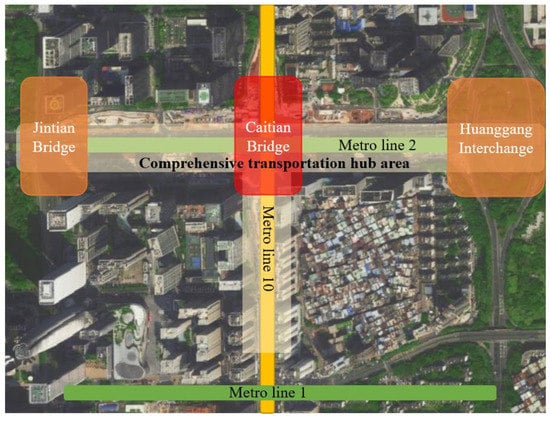
Figure 2. Map of Caitian Bridge and comprehensive transportation hub.
As a continuous girder bridge, Caitian Bridge is arranged as 20 + 25 × 4 + 20 m, the width along the transverse direction is 28.5 m, which consists of east and west parts with individual widths of 14.25 m, and the clearance under the bridge is 1.6 m~5.8 m, as shown in Figure 3. The standard cross-section of the main girder is shown in Figure 4.
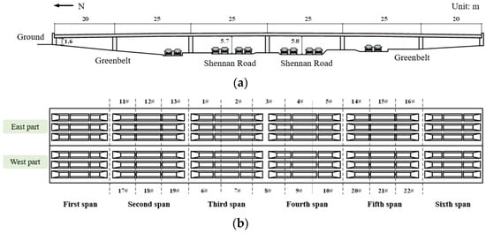
Figure 3. Span Arrangement of Main Bridge of Caitian Overpass Bridge (Unit: m). (a) Elevation diagram; (b) plan diagram.
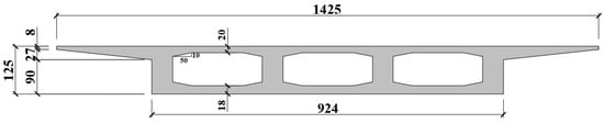
Figure 4. Schematic diagram of main girder standard section (Unit: cm).
According to the Chinese standard of General Specifications for the Design of Highway Bridge and Culverts (JTG D60-2015) [14], the design load is a vehicle load over 20 levels and a trailer load of 120. The superstructure of the main bridge is a continuous box girder with equal cross-sectional prestressed concrete, with a cross-section of a single box and three cells, and a concrete grade of C45. The girder is arranged with longitudinal prestressed tendons of Ryb = 1860 MPa low relaxation steel strand, an XM15-7 anchor mat is used, and the tensioning control stress is 1295 MPa. To reduce the prestress loss due to friction, the XL15-7 connector is installed in the box girder at 6.25 m on both sides of the middle pier. All the piers adopt Φ1.2 m double-column piers with bored pile foundations.
3. Comparison of Demolition Schemes
To minimize the negative impact on the normal work and life of residents, the management has limited the demolition of the Caitian Bridge to within 32 h and must satisfy the requirements of safety, high efficiency, and low pollution. Furthermore, based on the surrounding environment of the bridge, the demolition scheme for Caitian Bridge must also consider the following:
-
Safety management of traffic;
-
Impact on the structural stress and operational safety of the shield tunneling section of the existing metro line 2;
-
Reasonable selection of mechanical equipment, equipment quantity investment, and layout scheme;
-
Selection of transportation equipment and transportation plan for dismantled girder sections.
A comparative analysis of these three schemes is conducted, taking the impact on traffic, demolition time, cost, environmental pollution, etc., into consideration, as shown in Table 1.
Table 1. Qualitative comparison of demolition schemes.
| Demolition Schemes | Traffic Control | Time | Advantages | Disadvantages |
|---|---|---|---|---|
| Static cutting supported by scaffold | Half closure | 160 h | Mature technology, safe and reliable construction | Large material consumption |
| Direct mechanical chiseling | All closure | 48 h | Low-cost and simple construction | Noise and dust pollution |
| SPMT technology + large segment cutting | Half closure | 28 h | Flexible construction and traffic organization | High demand for equipment, immature technology and high cost |
To quantitatively compare the impact of three construction schemes on the environment, based on the Life Cycle Assessment (LCA), the carbon emissions during the demolition process of Caitian Bridge are estimated. According to the Standard of building carbon emission calculation (GBT 51366-2019) [15], a model of total carbon emission for the bridge demolition stage is established. This model mainly contains carbon emissions during the demolition stage and waste transportation. Among them, the former mainly comes from labor, machinery, etc., while the latter mainly comes from vehicle transportation of construction waste, as shown in Figure 5.
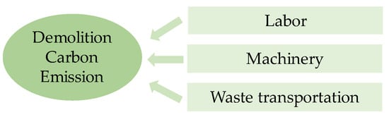
Figure 5. Components of demolition carbon emission.
The model can be expressed as:
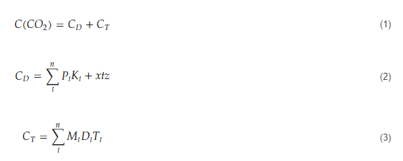 where,
𝐶(𝐶𝑂2) = total carbon emissions during the bridge demolition stage, kgCO2e;
𝐶𝐷 = carbon emissions from labor and machinery, kgCO2e;
𝐶𝑇 = carbon emissions from waste transportation, kgCO2e;
𝑃𝑖 = shift number of the 𝑖-th type of construction machinery, shift;
𝐾𝑖 = carbon emission coefficient of the 𝑖-th type of construction machinery, kgCO2e/shift;
𝑥 = number of workers, person;
𝑡 = working hours, one working day (eight hours);
𝑧 = carbon emission coefficient of a single person per working day, kgCO2e/(person ·working day);
𝑀𝑖 = total amount of the 𝑖-th type of waste, t;
𝐷𝑖 = average transportation distance of the 𝑖-th type of waste, km;
𝑇𝑖 = carbon emission coefficient of the 𝑖-th type of waste transportation with unit weight and distance, kgCO2e/(t·km).
Among them, there is no unified standard for the carbon emission coefficient of labor. Based on statistical data from the World Resources Institute and other research on carbon emission coefficient, bridge demolition workers are regarded as high-intensity workers, with a value of 4.16 kgCO2e/(person·workday) [16]. During the operation of construction machinery, energy consumption leads to significant carbon emissions. The main transportation method for construction waste is road transportation, and the waste is transported to a temporary girder storage yard which is 300 m away from the construction site. The corresponding carbon emission factors for mechanical operation and transportation refer to the Standard of building carbon emission calculation (GBT 51366-2019) [15].
Based on Formulas (1)–(3), the calculated carbon emissions generated by the three construction schemes during the demolition stage are shown in Table 2. Comprehensively considering the results in Table 1 and Table 2, compared to the other two schemes, the “SPMT technology + large segment cutting” scheme requires higher construction costs but can flexibly carry out the construction with a relatively short construction period. Additionally, the total carbon emissions during the demolition process are significantly lower than the other two schemes, with about 1/3 of carbon emissions from other schemes. Therefore, the impact on the environment is minimized, and the comprehensive socio-economic cost is the least. Thus, the “SPMT technology + large segment cutting” scheme is more suitable for the demolition of the Caitian Bridge.
Table 2. Carbon emissions for three schemes.
| Scheme | Labor (kgCO2e) |
Machinery (kgCO2e) |
Transportation (kgCO2e) |
Total (kgCO2e) |
|---|---|---|---|---|
| Static cutting supported by scaffold | 5907.2 | 66,075.9 | 281.8 | 72,264.9 |
| Direct mechanical chiseling | 2362.9 | 78,761.2 | 281.8 | 81,405.8 |
| SPMT technology + large segment cutting | 1033.8 | 24,789.7 | 227.2 | 26,050.7 |
4. Demolition Scheme Based on SPMT Technology
For the “SPMT technology + large segment cutting” scheme, first, demolish the main girder, then sequentially demolish the piers, abutments, and foundations. During the process, the scaffold and SPMT are used as temporary support, and the diamond rope saws are adopted to cut large segments synchronously. Moreover, SPMT is used to transport the girder segments to the storage yard. According to on-site conditions and design documents, the main girder is divided into 22 segments for demolition and transportation. Figure 3b shows the schematic diagram of the main girder segment division, and Table 3 shows the information on segments for each span. The specific demolition and transportation steps are as follows:
Table 3. Segmentation information of each span.
| Spans (from North to South) |
First Span | Second Span | Third Span | Fourth Span | Fifth Span | Sixth Span | Pier | Total | ||||||||
|---|---|---|---|---|---|---|---|---|---|---|---|---|---|---|---|---|
| Segment length (m) | 1.5 | 1.2 | 1.8 | 2 | 10 | 10 | 11.12 | 12 | 12.5 | 12.5 | 1.8 | 2 | 1.08 | 2 | φ1.2 × 5 | - |
| Unit weight (kN) | 375 | 300 | 450 | 500 | 2500 | 2500 | 2780 | 3000 | 3125 | 3125 | 450 | 500 | 270 | 500 | 141.4 | - |
| Quantity | 2 | 2 | 18 | 2 | 4 | 2 | 2 | 2 | 4 | 2 | 6 | 4 | 2 | 18 | 20 | - |
| Total weight (kN) | 750 | 600 | 8100 | 1000 | 10,000 | 5000 | 5560 | 6000 | 12,500 | 6250 | 2700 | 2000 | 540 | 9000 | 2828 | 72,828 |
-
Existing bridge state, the temporary support of SPMT and scaffold are in place;
-
Cut the main girder near the side pier of the first span in the east part, and the first and sixth spans are supported by scaffold;
-
Cut and demolish segments 1# and 2# of the third span; the cantilever end of segment 3# is supported by SPMT;
-
Cut and demolish segment 3#, 4#, and 5# of the fourth span;
-
Cut and demolish segments 6# and 7# of the third span; the cantilever end of segment 8# is supported by SPMT;
-
Cut and demolish segment 8#, 9#, and 10# of the fourth span;
-
Cut and demolish the second and fifth spans of the east part in sequence, namely segments 11#~13# and 14#~16#;
-
Cut and demolish the second and fifth spans of the west part in sequence, namely segments 17#~19# and 20#~22#;
-
Cut and demolish the first and sixth spans of the east and west parts.
During demolition, SPMT has two main functions. The first is the supporting function, which temporarily supports the demolishing main girder; the second is the transportation function, which transports the demolished girder segment to the storage yard. Based on Table 3, the maximum weight of the demolished segment is approximately 3125 kN, with a width of 12.5 m and a length of 14.25 m. To satisfy the functional requirements, the DCMC 8-axis SPMT is selected, with a length of 15.4 m, a wheelbase of 1.4 m, a width of 2.43 m, a height of 1.5 m, the load capacity of 300 kN to 350 kN per axis, and a single vehicle capacity of 2400 kN to 2800 kN. Each demolished segment is transported to the girder storage yard using 2 SPMTs, and a total of 9 SPMTs are selected for each single cutting segment.
According to the actual bridge alignment survey, the clearance at the bottom of the middle four spans is 5.28 m~5.97 m, but the height range of DCMC 8-axis SPMT is 1.15 m~1.85 m. Therefore, to satisfy the temporary support requirement, two types of height-adjusted jig frames are designed, with heights of 4.42 m and 3.92 m, respectively, and the height adjustment ranges of 5.57 m–6.27 m and 5.07 m–5.77 m, respectively. The combined structure of the selected SPMT and jig frame is shown in Figure 6.
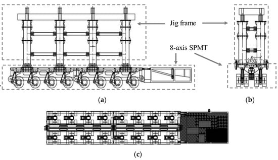
Figure 6. The combined structure of 8-axis SPMT and adjustable jig frame. (a) Front view; (b) left view; and (c) vertical view.
This entry is adapted from the peer-reviewed paper 10.3390/buildings13061379
This entry is offline, you can click here to edit this entry!