One promising option for reducing carbon emissions is the deployment of carbon capture, utilization, and storage technologies (CCUS) to achieve climate goals. However, for large-scale deployment of underground carbon storage, it is essential to develop technically sound, safe, and cost-effective CO2 injection and well control strategies. This involves sophisticated balancing of various factors such as subsurface engineering policies, technical constraints, and economic trade-offs. Optimization techniques are the best tools to manage this complexity and ensure that CCUS projects are economically viable while maintaining safety and environmental standards.
- Carbon Capture Utilization and Storage (CCUS)
- Carbon Capture and Storage (CCS)
- CO2 injection and well control strategies
- injection policies
1. Pressure Management: Controlling Pressure Build-Up and Geomechanical Complications
- (1)
-
Closed systems, where the storage formation is surrounded by impervious boundaries and blocked vertically by impervious sealing units.
- (2)
-
Semi-closed systems, where the storage system is enclosed laterally by impervious boundaries but overlain and/or underlain by semi-previous sealing units.
- (3)
-
Open system, where the lateral boundaries are too far to be affected by pressure disturbances [1].
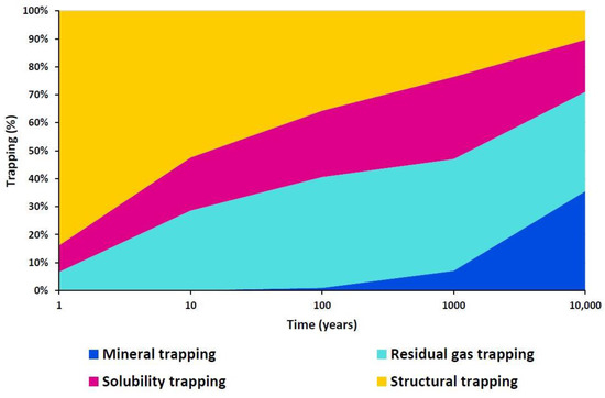
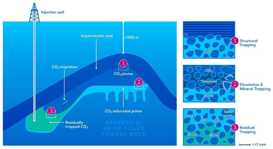
2. Geological Storage Security: Improving Residual and Solubility Trapping
3. CO2-EOR Carbon Storage Compliance: Joint Co-Optimization
4. Displacement Control: Sweep Efficiency Performance Control in CO2-EGR Applications
This entry is adapted from the peer-reviewed paper 10.3390/cleantechnol5020031
References
- Zhou, Q.; Birkholzer, J.T.; Tsang, C.-F.; Rutqvist, J. A Method for Quick Assessment of CO2 Storage Capacity in Closed and Semi-Closed Saline Formations. Int. J. Greenh. Gas Control 2008, 2, 626–639.
- Ehlig-Economides, C.; Economides, M.J. Sequestering Carbon Dioxide in a Closed Underground Volume. J. Pet. Sci. Eng. 2010, 70, 123–130.
- IPCC (Intergovernmental Panel on Climate Change). IPCC Special Report on Carbon Dioxide Capture and Storage; Cambridge University Press: Cambridge, UK; New York, NY, USA, 2005.
- Kaldi, J.; Bachu, S. Geologic Carbon Sequestration: Prediction and Verification. In Geologic Carbon Sequestration: Prediction and Verification, Proceedings of the AAPG/SEG/SPE Hedberg Conference, Vancouver, BC, Canada, 16–19 August 2009; AAPG Search and Discovery: Tulsa, OK, USA, 2009.
- Nicot, J.-P. Evaluation of Large-Scale CO2 Storage on Fresh-Water Sections of Aquifers: An Example from the Texas Gulf Coast Basin. Int. J. Greenh. Gas Control 2008, 2, 582–593.
- Zweigel, P.; Hamborg, M.; Arts, R.; Lothe, A.; Sylta, Ø.; Tømmerås, A. Prediction of Migration of CO2 Injected into an Underground Depository: Reservoir Geology and Migration Modelling in the Sleipner Case (North Sea). In Proceedings of the Fifth International Conference on Greenhouse Gas Control Technologies, Cairns, Australia, 13–16 August 2000.
- Zhou, Q.; Birkholzer, J.T.; Mehnert, E.; Lin, Y.-F.; Zhang, K. Modeling Basin- and Plume-Scale Processes of CO2 Storage for Full-Scale Deployment. Groundwater 2009, 48, 494–514.
- Birkholzer, J.; Zhou, Q.; Tsang, C. Large-Scale Impact of CO2 Storage in Deep Saline Aquifers: A Sensitivity Study on Pressure Response in Stratified Systems. Int. J. Greenh. Gas Control 2009, 3, 181–194.
- Szulczewski, M.L.; MacMinn, C.W.; Juanes, R. How Pressure Buildup and CO2 Migration Can Both Constrain Storage Capacity in Deep Saline Aquifers. Energy Procedia 2011, 4, 4889–4896.
- Sarkarfarshi, M.; Malekzadeh, F.A.; Gracie, R.; Dusseault, M.B. Parametric Sensitivity Analysis for CO2 Geosequestration. Int. J. Greenh. Gas Control 2014, 23, 61–71.
- Zhao, H.; Liao, X.; Chen, Y.; Zhao, X. Sensitivity Analysis of CO2 Sequestration in Saline Aquifers. Pet. Sci. 2010, 7, 372–378.
- Cameron, D.A.; Durlofsky, L.J. Optimization of Well Placement, CO2 Injection Rates and Brine Cycling for Geological Carbon Sequestration. Int. J. Greenh. Gas Control 2012, 10, 100–112.
- Birkholzer, J.T.; Cihan, A.; Zhou, Q. Impact-Driven Pressure Management via Targeted Brine Extraction—Conceptual Studies of CO2 Storage in Saline Formations. Int. J. Greenh. Gas Control 2012, 7, 168–180.
- Court, B.; Bandilla, K.W.; Celia, M.A.; Buscheck, T.A.; Nordbotten, J.M.; Dobossy, M.; Janzen, A. Initial Evaluation of Advantageous Synergies Associated with Simultaneous Brine Production and CO2 Geological Sequestration. Int. J. Greenh. Gas Control 2012, 8, 90–100.
- Buscheck, T.A.; Sun, Y.; Hao, Y.; Wolery, T.J.; Bourcier, W.; Tompson, A.F.B.; Jones, E.D.; Julio Friedmann, S.; Aines, R.D. Combining Brine Extraction, Desalination and Residual-Brine Reinjection with CO2 Storage in Saline Formations: Implications for Pressure Management, Capacity and Risk Mitigation. Energy Procedia 2011, 4, 4283–4290.
- Cihan, A.; Birkholzer, J.T.; Bianchi, M. Optimal Well Placement and Brine Extraction for Pressure Management during CO2 Sequestration. Int. J. Greenh. Gas Control 2015, 42, 175–187.
- Santibanez-Borda, E.; Govindan, R.; Elahi, N.; Korre, A.; Durucan, S. Maximising the Dynamic CO2 Storage Capacity through the Optimisation of CO2 Injection and Brine Production Rates. Int. J. Greenh. Gas. Control 2019, 80, 76–95.
- Al Hameli, F.; Belhaj, H.; al Dhuhoori, M. CO2 Sequestration Overview in Geological Formations: Trapping Mechanisms Matrix Assessment. Energies 2022, 15, 7805.
- Shamshiri, H.; Jafarpour, B. Controlled CO2 Injection into Heterogeneous Geologic Formations for Improved Solubility and Residual Trapping. Water Resour. Res. 2012, 48, W02530.
- Weir, G.J.; White, S.P.; Kissling, W.M. Reservoir Storage and Containment of Greenhouse Gases. Energy Convers. Manag. 1995, 36, 531–534.
- Lindeberg, E.; Wessel-Berg, D. Vertical Convection in an Aquifer Column under a Gas Cap of CO2. Energy Convers. Manag. 1997, 38, S229–S234.
- McPherson, B.J.O.L.; Cole, B.S. Multiphase CO2 Flow, Transport and Sequestration in the Powder River Basin, Wyoming, USA. J. Geochem. Explor. 2000, 69–70, 65–69.
- Ennisking, J.; Paterson, L. Rate of Dissolution Due to Convective Mixing in the Underground Storage of Carbon Dioxide. In Greenhouse Gas Control Technologies, Proceedings of the 6th International Conference on Greenhouse Gas Control Technologies, Kyoto, Japan, 1–4 October 2002; Elsevier: Amsterdam, The Netherlands, 2003; pp. 507–510.
- Kumar, A.; Ozah, R.; Noh, M.; Pope, G.A.; Bryant, S.; Sepehrnoori, K.; Lake, L.W. Reservoir Simulation of CO2 Storage in Deep Saline Aquifers. SPE J. 2005, 10, 336–348.
- Obi, E.-O.I.; Blunt, M.J. Streamline-Based Simulation of Carbon Dioxide Storage in a North Sea Aquifer. Water Resour. Res. 2006, 42, W03414.
- Qi, R.; Laforce, T.; Blunt, M. Design of Carbon Dioxide Storage in Aquifers. Int. J. Greenh. Gas Control 2009, 3, 195–205.
- Juanes, R.; Spiteri, E.J.; Orr, F.M.; Blunt, M.J. Impact of Relative Permeability Hysteresis on Geological CO2 Storage. Water Resour. Res. 2006, 42, W12418.
- Rackley, S.A. Carbon Capture and Storage; Elsevier: Amsterdam, The Netherlands, 2017.
- Matter, J.M.; Kelemen, P.B. Permanent Storage of Carbon Dioxide in Geological Reservoirs by Mineral Carbonation. Nat. Geosci. 2009, 2, 837–841.
- Raza, A.; Gholami, R.; Rezaee, R.; Bing, C.H.; Nagarajan, R.; Hamid, M.A. CO2 Storage in Depleted Gas Reservoirs: A Study on the Effect of Residual Gas Saturation. Petroleum 2018, 4, 95–107.
- Liu, Q.; Maroto-Valer, M.M. Study of Mineral Trapping of CO2 and Seal Leakage Mitigation. Energy Procedia 2014, 63, 5490–5494.
- Leonenko, Y.; Keith, D.W. Reservoir Engineering To Accelerate the Dissolution of CO2 Stored in Aquifers. Environ. Sci. Technol. 2008, 42, 2742–2747.
- Kumar, D. Optimization of Well Settings to Maximize Residually Trapped CO2 in Geologic Carbon Sequestration. Master’s Thesis, Stanford University, Stanford, CA, USA, 2007.
- Hassanzadeh, H.; Pooladi-Darvish, M.; Keith, D.W. Accelerating CO2 Dissolution in Saline Aquifers for Geological Storage—Mechanistic and Sensitivity Studies. Energy Fuels 2009, 23, 3328–3336.
- Nghiem, L.; Yang, C.; Shrivastava, V.; Kohse, B.; Hassam, M.; Card, C. Risk Mitigation through the Optimization of Residual Gas and Solubility Trapping for CO2 Storage in Saline Aquifers. Energy Procedia 2009, 1, 3015–3022.
- Nghiem, L.; Shrivastava, V.; Kohse, B.; Hassam, M.; Yang, C. Simulation and Optimization of Trapping Processes for CO2 Storage in Saline Aquifers. J. Can. Pet. Technol. 2010, 49, 15–22.
- Shafaei, M.J.; Abedi, J.; Hassanzadeh, H.; Chen, Z. Reverse Gas-Lift Technology for CO2 Storage into Deep Saline Aquifers. Energy 2012, 45, 840–849.
- Rasmusson, K.; Rasmusson, M.; Tsang, Y.; Niemi, A. A Simulation Study of the Effect of Trapping Model, Geological Heterogeneity and Injection Strategies on CO2 Trapping. Int. J. Greenh. Gas Control 2016, 52, 52–72.
- Vo Thanh, H.; Sugai, Y.; Nguele, R.; Sasaki, K. Robust Optimization of CO2 Sequestration through a Water Alternating Gas Process under Geological Uncertainties in Cuu Long Basin, Vietnam. J. Nat. Gas. Sci. Eng. 2020, 76, 103208.
- Burton, M.; Bryant, S.L. Surface Dissolution: Minimizing Groundwater Impact and Leakage Risk Simultaneously. Energy Procedia 2009, 1, 3707–3714.
- Tao, Q.; Bryant, S.L. Optimization of Injection/Extraction Rates for Surface-Dissolution Process. SPE J. 2014, 19, 598–607.
- Kovscek, A.R.; Cakici, M.D. Geologic Storage of Carbon Dioxide and Enhanced Oil Recovery. II. Cooptimization of Storage and Recovery. Energy Convers. Manag. 2005, 46, 1941–1956.
- Leach, A.; Mason, C.F.; van‘t Veld, K. Co-Optimization of Enhanced Oil Recovery and Carbon Sequestration. Resour. Energy Econ. 2011, 33, 893–912.
- Malik, Q.M.; Islam, M.R. CO2 Injection in the Weyburn Field of Canada: Optimization of Enhanced Oil Recovery and Greenhouse Gas Storage with Horizontal Wells. In All Days, Proceedings of the SPE/DOE Improved Oil Recovery Symposium, Tulsa, OK, USA, 3–5 April 2000; OnePetro: Richardson, TX, USA, 2000.
- Jessen, K.; Kovscek, A.R.; Orr, F.M. Increasing CO2 Storage in Oil Recovery. Energy Convers. Manag. 2005, 46, 293–311.
- Asghari, K.; Aldliwe, A. Optimization of Carbon Dioxide Sequestration and Improved Oil Recovery in Oil Reservoirs. In Greenhouse Gas Control Technologies 7; Elsevier: Amsterdam, The Netherlands, 2005; pp. 381–389.
- Asghari, K.; Al-Dliwe, A.; Mahinpey, N. Effect of Operational Parameters on Carbon Dioxide Storage Capacity in a Heterogeneous Oil Reservoir: A Case Study. Ind. Eng. Chem. Res. 2006, 45, 2452–2456.
- Babadagli, T. Optimization of CO2 Injection for Sequestration/Enhanced Oil Recovery and Current Status in Canada. In Advances in the Geological Storage of Carbon Dioxide; Kluwer Academic Publishers: Dordrecht, The Netherlands; pp. 261–270.
- Trivedi, J.J.; Babadagli, T. Optimal Injection Strategies for CO2 and Flue Gas Sequestration during Tertiary Oil Recovery. Oil Gas Eur. Mag. 2007, 33, 22–26.
- Trivedi, J.J.; Babadagli, T.; Lavoie, R.G.; Nimchuk, D. Acid gas sequestration during tertiary oil recovery: Optimal injection strategies and importance of operational parameters. J. Can. Pet. Technol. 2007, 46, 60–68.
- Qi, R.; LaForce, T.C.; Blunt, M.J. Design of Carbon Dioxide Storage in Oilfields. In All Days, Proceedigns of the SPE Annual Technical Conference and Exhibition, Denver, CO, USA, 21–24 September 2008; OnePetro: Richardson, TX, USA, 2008.
- Pamukçu, Y.Z.; Gumrah, F. A Numerical Simulation Study of Carbon-Dioxide Sequestration into a Depleted Oil Reservoir. Energy Sources Part A Recovery Util. Environ. Eff. 2009, 31, 1348–1367.
- Xiao, C.; Harris, M.L.; Wang, F.; Grigg, R. Field Testing and Numerical Simulation of Combined CO2 Enhanced Oil Recovery and Storage in the SACROC Unit. In All Days, Proceedings of the Canadian Unconventional Resources Conference, Calgary, AB, Canada, 15–17 November 2011; OnePetro: Richardson, TX, USA, 2011.
- Sobers, L.E.; Blunt, M.J.; LaForce, T.C. Design of Simultaneous Enhanced Oil Recovery and Carbon Dioxide Storage With Potential Application to Offshore Trinidad. SPE J. 2013, 18, 345–354.
- Li, L.; Khorsandi, S.; Johns, R.T.; Dilmore, R.M. CO2 Enhanced Oil Recovery and Storage Using a Gravity-Enhanced Process. Int. J. Greenh. Gas Control 2015, 42, 502–515.
- Ahmadi, M.A.; Pouladi, B.; Barghi, T. Numerical Modeling of CO2 Injection Scenarios in Petroleum Reservoirs: Application to CO2 Sequestration and EOR. J. Nat. Gas. Sci. Eng. 2016, 30, 38–49.
- Ampomah, W.; Balch, R.; Grigg, R.B.; Cather, M.; Gragg, E.; Will, R.A.; White, M.; Moodie, N.; Dai, Z. Performance Assessment of CO2-Enhanced Oil Recovery and Storage in the Morrow Reservoir. Geomech. Geophys. Geo-Energy Geo-Resour. 2017, 3, 245–263.
- Kamali, F.; Hussain, F. Field-Scale Simulation of CO2 Enhanced Oil Recovery and Storage through SWAG Injection Using Laboratory Estimated Relative Permeabilities. J. Pet. Sci. Eng. 2017, 156, 396–407.
- Ampomah, W.; Balch, R.S.; Grigg, R.B.; McPherson, B.; Will, R.A.; Lee, S.; Dai, Z.; Pan, F. Co-Optimization of CO2-EOR and Storage Processes in Mature Oil Reservoirs. Greenh. Gases Sci. Technol. 2017, 7, 128–142.
- Mokhtari, R.; Ayatollahi, S.; Hamid, K.; Zonnouri, A. Co-Optimization of Enhanced Oil Recovery and Carbon Dioxide Sequestration in a Compositionally Grading Iranian Oil Reservoir; Technical and Economic Approach. In Day 1 Mon, Proceedings of the Abu Dhabi International Petroleum Exhibition & Conference, Abu Dhabi, United Arab Emirates, 7 November 2016; OnePetro: Richardson, TX, USA, 2016.
- Eshraghi, S.E.; Rasaei, M.R.; Zendehboudi, S. Optimization of Miscible CO2 EOR and Storage Using Heuristic Methods Combined with Capacitance/Resistance and Gentil Fractional Flow Models. J. Nat. Gas. Sci. Eng. 2016, 32, 304–318.
- Kamali, F.; Cinar, Y. Co-Optimizing Enhanced Oil Recovery and CO2 Storage by Simultaneous Water and CO2 Injection. Energy Explor. Exploit. 2014, 32, 281–300.
- Dai, Z.; Middleton, R.; Viswanathan, H.; Fessenden-Rahn, J.; Bauman, J.; Pawar, R.; Lee, S.-Y.; McPherson, B. An Integrated Framework for Optimizing CO2 Sequestration and Enhanced Oil Recovery. Environ. Sci. Technol. Lett. 2014, 1, 49–54.
- Su, K.; Liao, X.; Zhao, X.; Zhang, H. Coupled CO2 Enhanced Oil Recovery and Sequestration in China’s Demonstration Project: Case Study and Parameter Optimization. Energy Fuels 2013, 27, 378–386.
- Forooghi, A.; Hamouda, A.A.; Eilertsen, T. Co-Optimization of CO2 EOR and Sequestration Process in a North Sea Chalk Reservoir. In All Days, Proceedings of the SPE/EAGE Reservoir Characterization and Simulation Conference, Abu Dhabi, United Arab Emirates, 19–21 October 2009; OnePetro: Richardson, TX, USA, 2009.
- Le Van, S.; Chon, B.H. Evaluating the Critical Performances of a CO2–Enhanced Oil Recovery Process Using Artificial Neural Network Models. J. Pet. Sci. Eng. 2017, 157, 207–222.
- Kwak, D.-H.; Kim, J.-K. Techno-Economic Evaluation of CO2 Enhanced Oil Recovery (EOR) with the Optimization of CO2 Supply. Int. J. Greenh. Gas Control 2017, 58, 169–184.
- Song, Z.; Li, Z.; Wei, M.; Lai, F.; Bai, B. Sensitivity Analysis of Water-Alternating-CO2 Flooding for Enhanced Oil Recovery in High Water Cut Oil Reservoirs. Comput. Fluids 2014, 99, 93–103.
- Safarzadeh, M.A.; Motahhari, S.M. Co-Optimization of Carbon Dioxide Storage and Enhanced Oil Recovery in Oil Reservoirs Using a Multi-Objective Genetic Algorithm (NSGA-II). Pet. Sci. 2014, 11, 460–468.
- Ettehadtavakkol, A.; Lake, L.W.; Bryant, S.L. CO2-EOR and Storage Design Optimization. Int. J. Greenh. Gas Control 2014, 25, 79–92.
- Jahangiri, H.R.; Zhang, D. Ensemble Based Co-Optimization of Carbon Dioxide Sequestration and Enhanced Oil Recovery. Int. J. Greenh. Gas Control 2012, 8, 22–33.
- Jahangiri, H.R.; Zhang, D. Optimization of the Net Present Value of Carbon Dioxide Sequestration and Enhanced Oil Recovery. In All Days, Proceedings of the Offshore Technology Conference, Houston, TX, USA, 2–5 May 2011; OnePetro: Richardson, TX, USA, 2011.
- Ghomian, Y.; Sepehrnoori, K.; Pope, G.A. Efficient Investigation of Uncertainties in Flood Design Parameters for Coupled CO2 Sequestration and Enhanced Oil Recovery. In All Days, Proceedings of the SPE International Conference on CO2 Capture, Storage, and Utilization, New Orleans, LA, USA, 10–12 November 2010; OnePetro: Richardson, TX, USA, 2010.
- Ghomian, Y.; Pope, G.A.; Sepehrnoori, K. Hysteresis and Field-Scale Optimization of WAG Injection for Coupled CO2-EOR and Sequestration. In All Days, Proceedings of the SPE Symposium on Improved Oil Recovery, Tulsa, OK, USA, 20–23 April 2008; OnePetro: Richardson, TX, USA, 2008.
- Ghomian, Y.; Urun, M.; Pope, G.A.; Sepehrnoori, K. Investigation of Economic Incentives for CO2 Sequestration. In All Days, Proceedings of the SPE Annual Technical Conference and Exhibition, Denver, CO, USA, 21–24 September 2008; OnePetro: Richardson, TX, USA, 2008.
- Liu, S.-Y.; Ren, B.; Li, H.-Y.; Yang, Y.-Z.; Wang, Z.-Q.; Wang, B.; Xu, J.-C.; Agarwal, R. CO2 Storage with Enhanced Gas Recovery (CSEGR): A Review of Experimental and Numerical Studies. Pet. Sci. 2022, 19, 594–607.
- Vanderburgt, M.; Cantle, J.; Boutkan, V. Carbon Dioxide Disposal from Coal-Based IGCC’s in Depleted Gas Fields. Energy Convers. Manag. 1992, 33, 603–610.
- Oldenburg, C.M.; Pruess, K.; Benson, S.M. Process Modeling of CO2 Injection into Natural Gas Reservoirs for Carbon Sequestration and Enhanced Gas Recovery. Energy Fuels 2001, 15, 293–298.
- Oldenburg, C.M.; Benson, S.M. Carbon Sequestration with Enhanced Gas Recovery: Identifying Candidate Sites for Pilot Study. In Proceedings of the First National Conference on Carbon Sequestration, Washington, DC, USA, 14–17 May 2001.
- Rebscher, D.; Oldenburg, C.M. Sequestration of Carbon Dioxide with Enhanced Gas Recovery-CaseStudy Altmark, North German Basin; Lawrence Berkeley National Lab. (LBNL): Berkeley, CA, USA, 2005.
- Fan, L.; Tan, Q.; Li, H.; Xu, J.; Wang, X.; Liu, S. Simulation on Effects of Injection Parameters on CO2 Enhanced Gas Recovery in a Heterogeneous Natural Gas Reservoir. Adv. Theory Simul. 2021, 4, 2100127.
- Kalra, S.; Wu, X. CO2 Injection for Enhanced Gas Recovery. In All Days, Proceedings of the SPE Western North American and Rocky Mountain Joint Meeting, Denver, CO, USA, 15–18 April 2014; OnePetro: Richardson, TX, USA, 2014.
- Al-Hashami, A.; Ren, S.R.; Tohidi, B. CO2 Injection for Enhanced Gas Recovery and Geo-Storage: Reservoir Simulation and Economics. In All Days, Proceedings of the SPE Europec/EAGE Annual Conference, Madrid, Spain, 13–16 June 2005; OnePetro: Richardson, TX, USA, 2005.
- Luo, F.; Xu, R.-N.; Jiang, P.-X. Numerical Investigation of the Influence of Vertical Permeability Heterogeneity in Stratified Formation and of Injection/Production Well Perforation Placement on CO2 Geological Storage with Enhanced CH4 Recovery. Appl. Energy 2013, 102, 1314–1323.
- Patel, M.J.; May, E.F.; Johns, M.L. Inclusion of Connate Water in Enhanced Gas Recovery Reservoir Simulations. Energy 2017, 141, 757–769.
- Clemens, T.; Wit, K. CO2 Enhanced Gas Recovery Studied for an Example Gas Reservoir. In All Days, Proceedings of the SPE Annual Technical Conference and Exhibition, San Antonio, TX, USA, 29 September–2 October 2002; OnePetro: Richardson, TX, USA, 2002.
- Jikich, S.A.; Smith, D.H.; Sams, W.N.; Bromhal, G.S. Enhanced Gas Recovery (EGR) with Carbon Dioxide Sequestration: A Simulation Study of Effects of Injection Strategy and Operational Parameters. In All Days, Proceedings of the SPE Eastern Regional Meeting, Pittsburgh, PA, USA, 7–11 October 2003; OnePetro: Richardson, TX, USA, 2003.
- Hussen, C.; Amin, R.; Madden, G.; Evans, B. Reservoir Simulation for Enhanced Gas Recovery: An Economic Evaluation. J. Nat. Gas Sci. Eng. 2012, 5, 42–50.
- Hou, Z.; Gou, Y.; Taron, J.; Gorke, U.J.; Kolditz, O. Thermo-Hydro-Mechanical Modeling of Carbon Dioxide Injection for Enhanced Gas-Recovery (CO2-EGR): A Benchmarking Study for Code Comparison. Environ. Earth Sci. 2012, 67, 549–561.
- Liu, S.; Agarwal, R.; Sun, B.; Wang, B.; Li, H.; Xu, J.; Fu, G. Numerical Simulation and Optimization of Injection Rates and Wells Placement for Carbon Dioxide Enhanced Gas Recovery Using a Genetic Algorithm. J. Clean. Prod. 2021, 280, 124512.
- Zangeneh, H.; Jamshidi, S.; Soltanieh, M. Coupled Optimization of Enhanced Gas Recovery and Carbon Dioxide Sequestration in Natural Gas Reservoirs: Case Study in a Real Gas Field in the South of Iran. Int. J. Greenh. Gas Control 2013, 17, 515–522.
- Biagi, J.; Agarwal, R.; Zhang, Z. Simulation and Optimization of Enhanced Gas Recovery Utilizing CO2. Energy 2016, 94, 78–86.